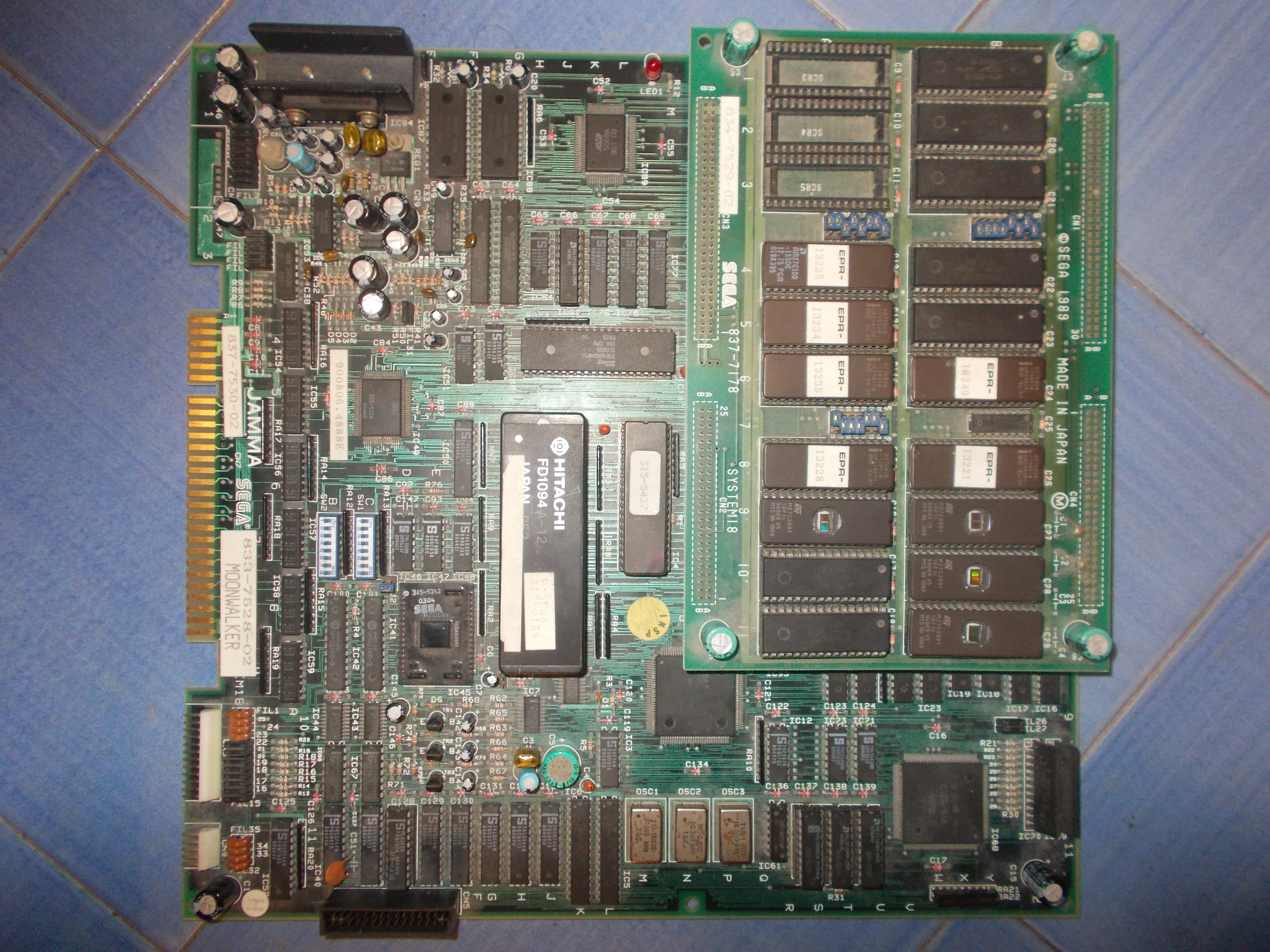
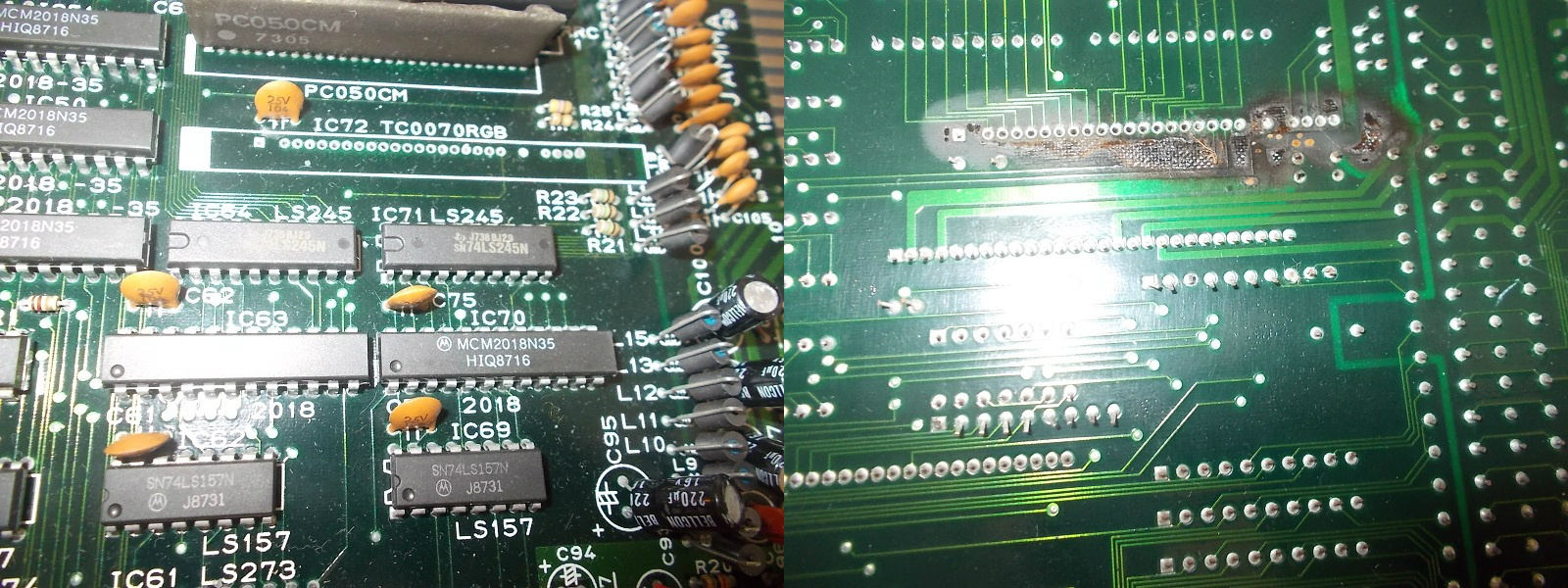
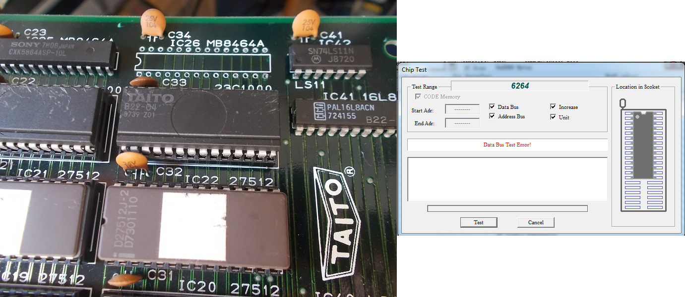
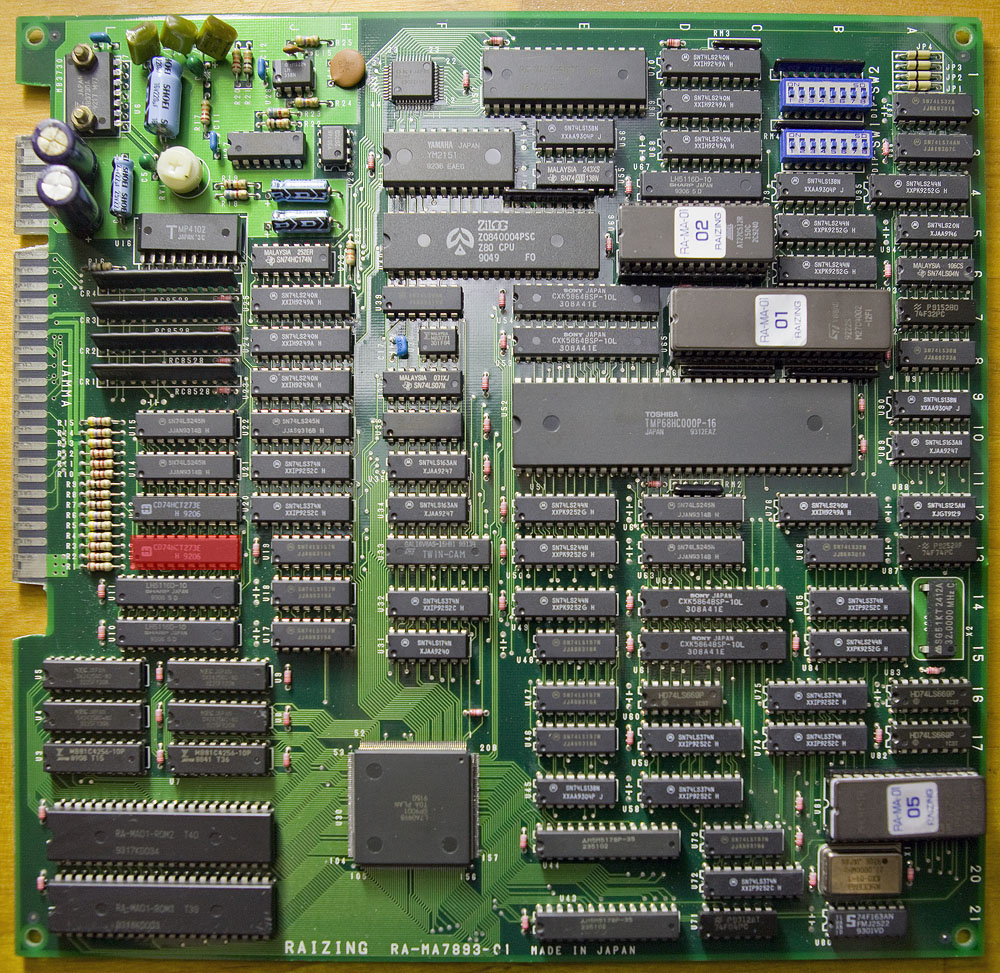
Received this original Bubble Bobble PCB for repair.Set is made of a CPU board :
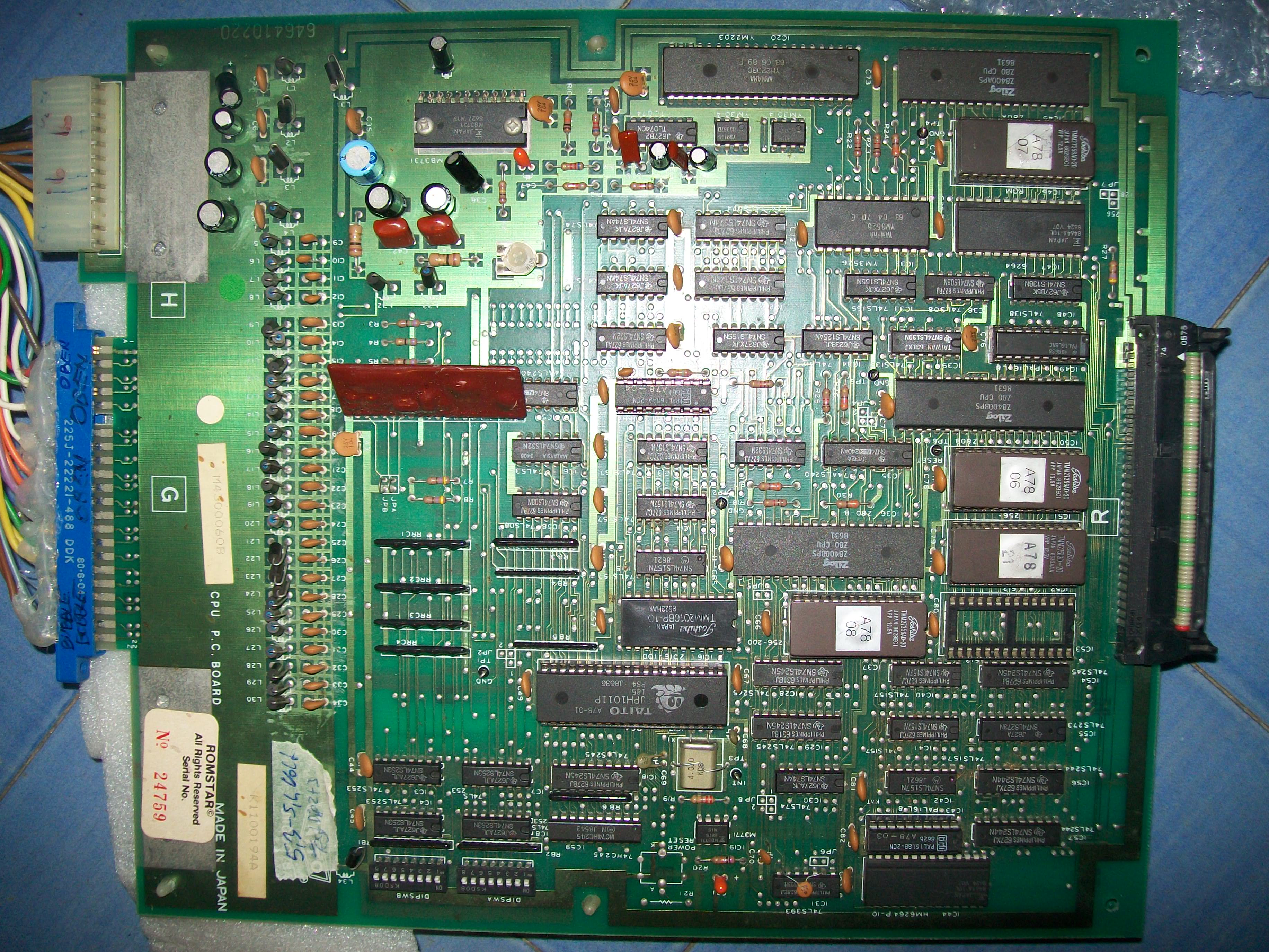
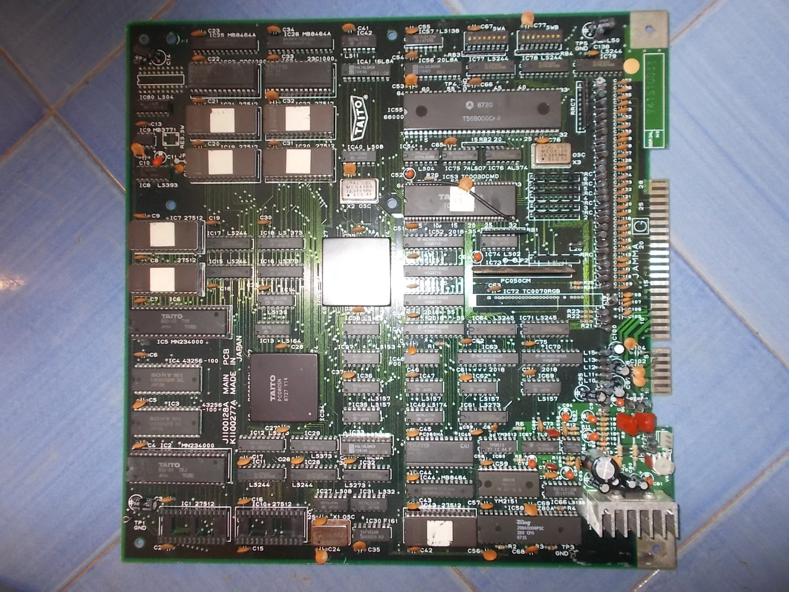
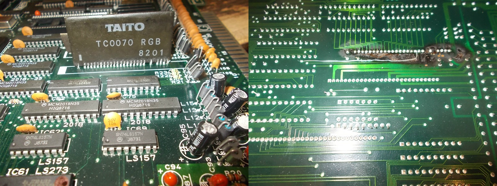
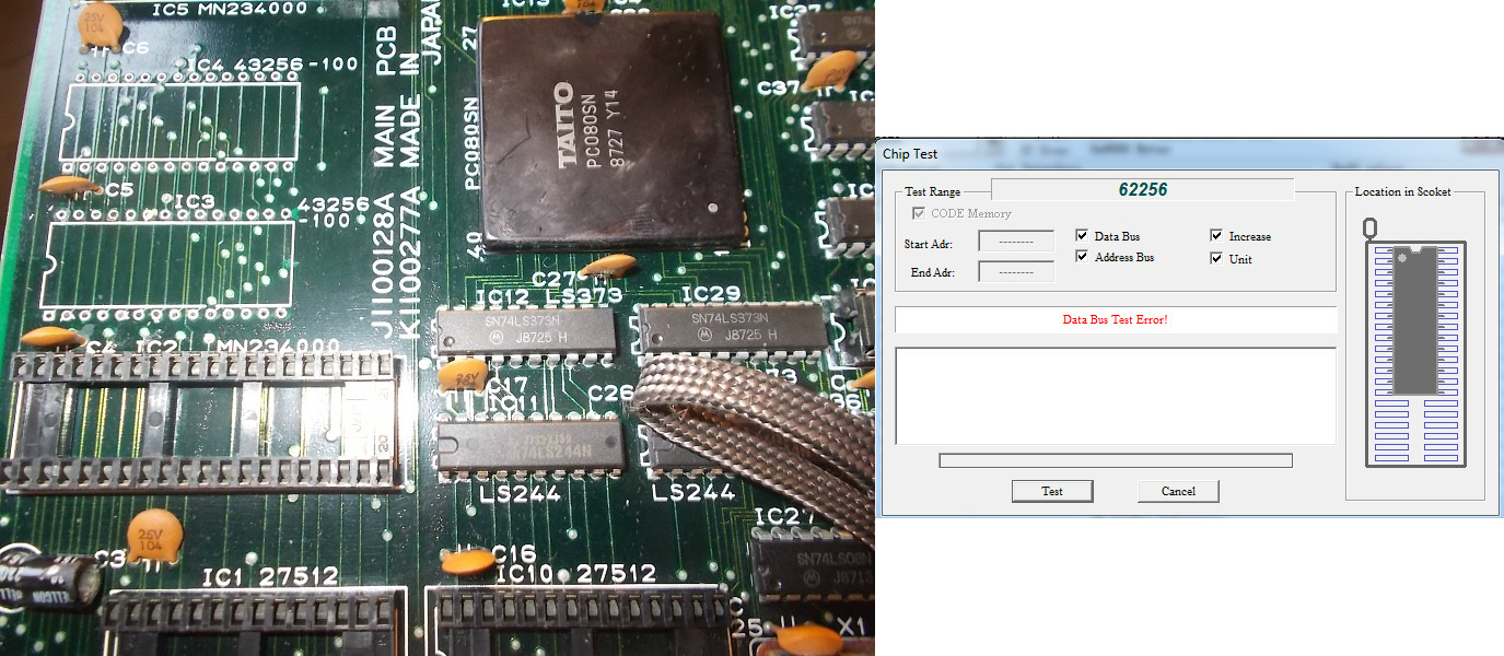
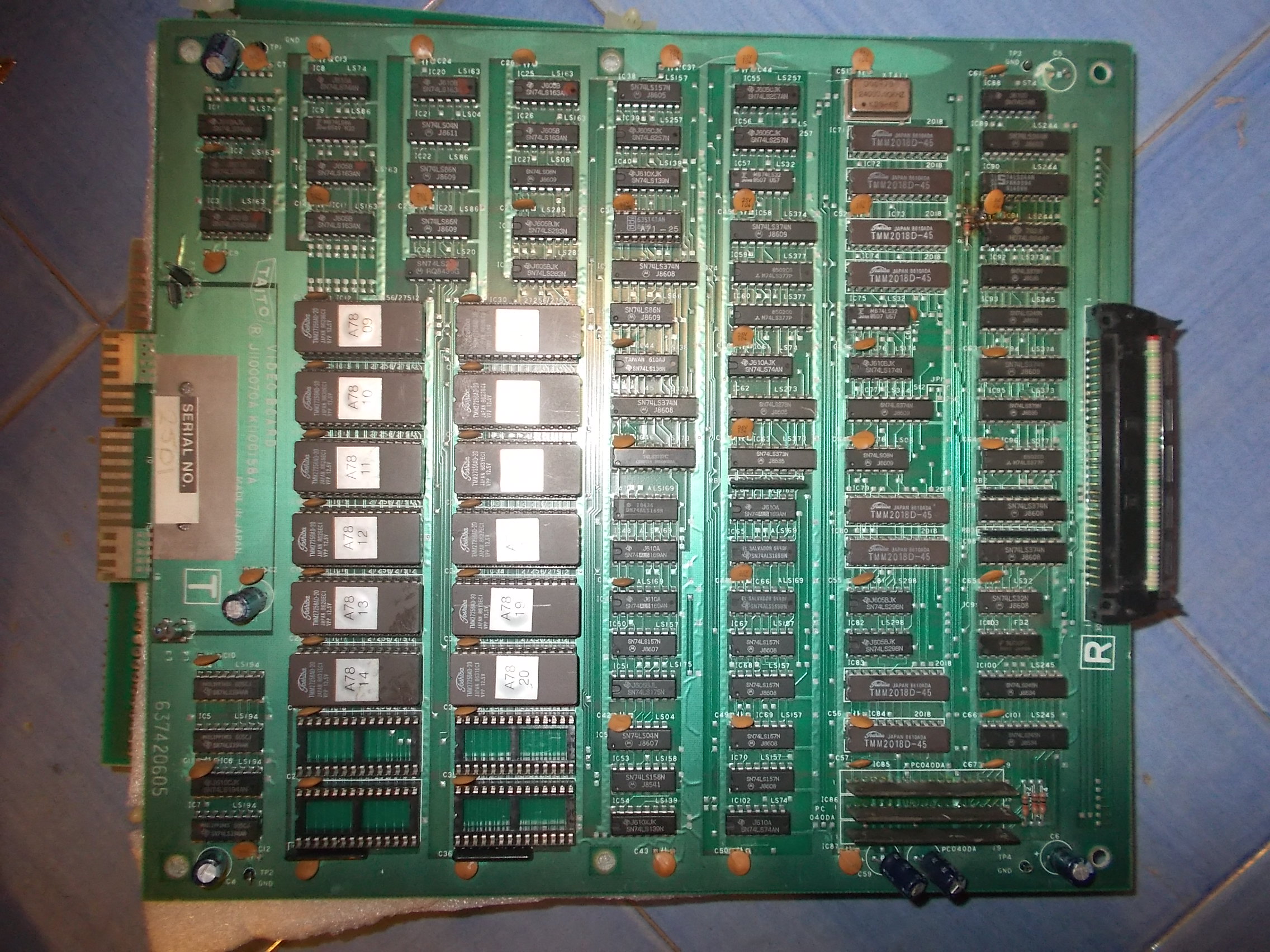
and a VIDEO one :
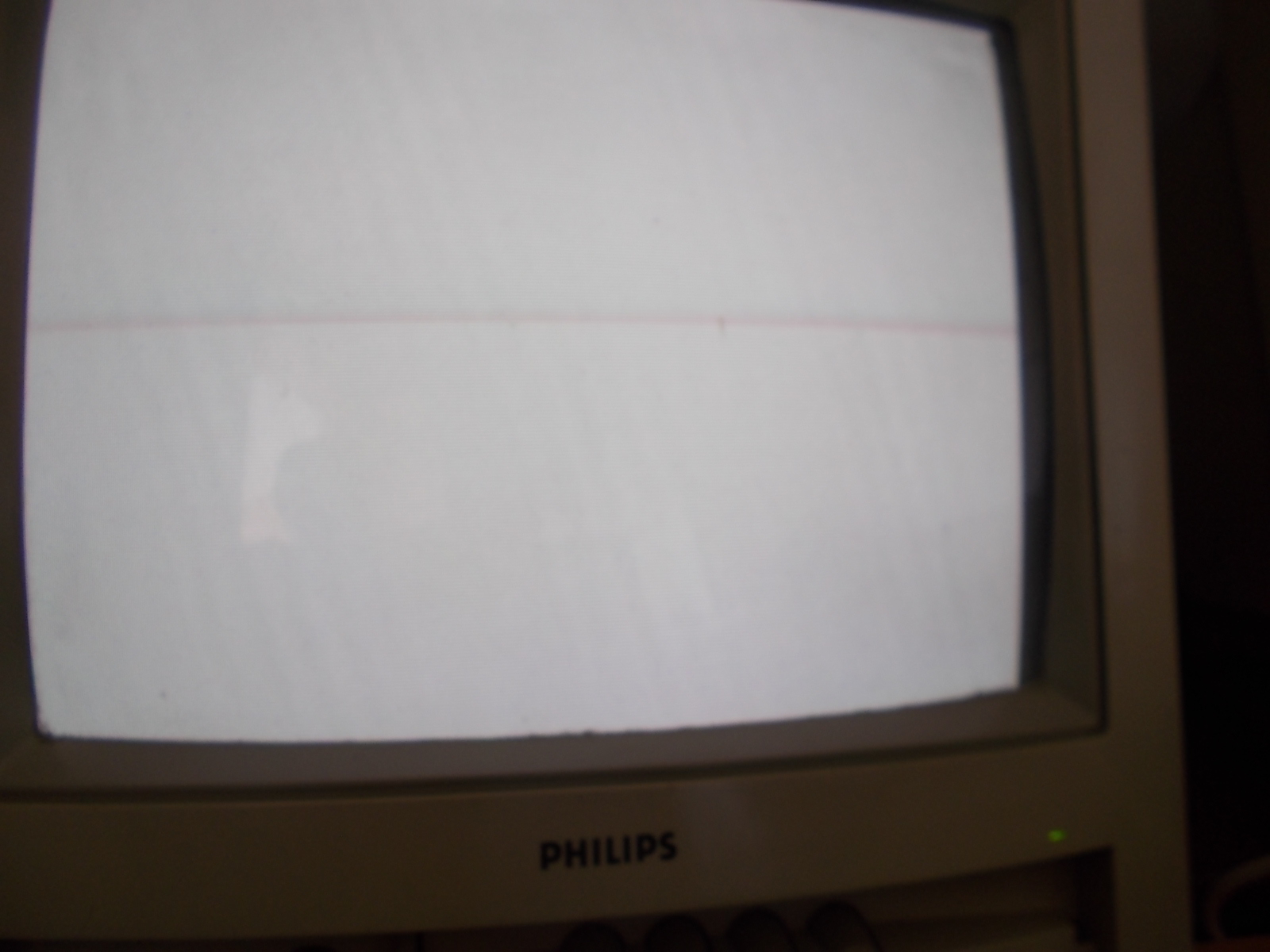
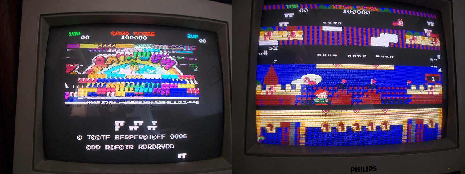
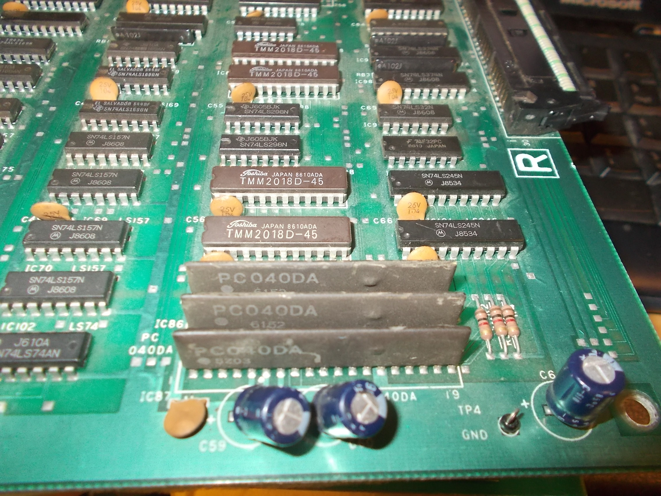
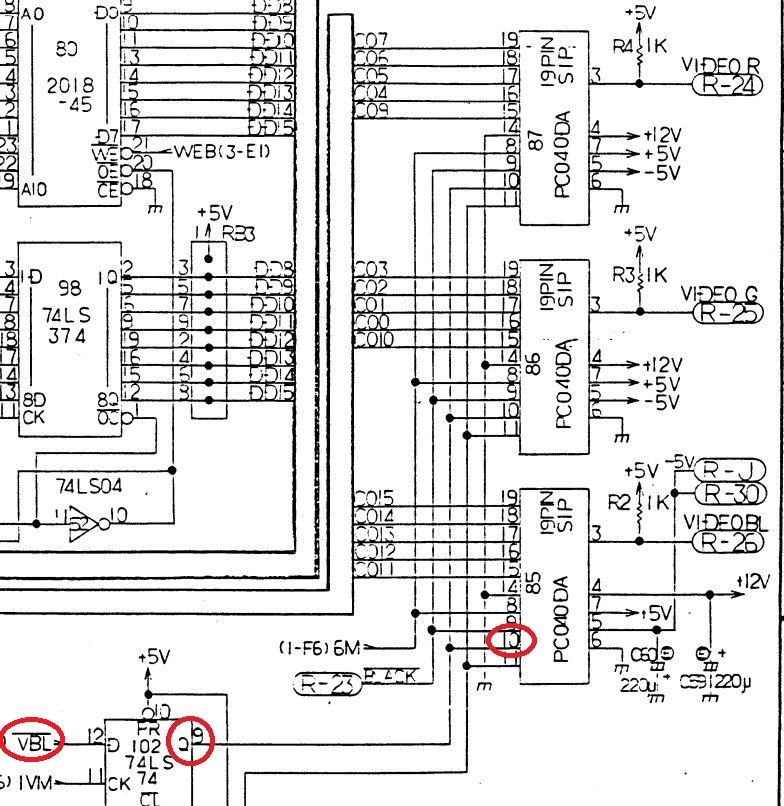
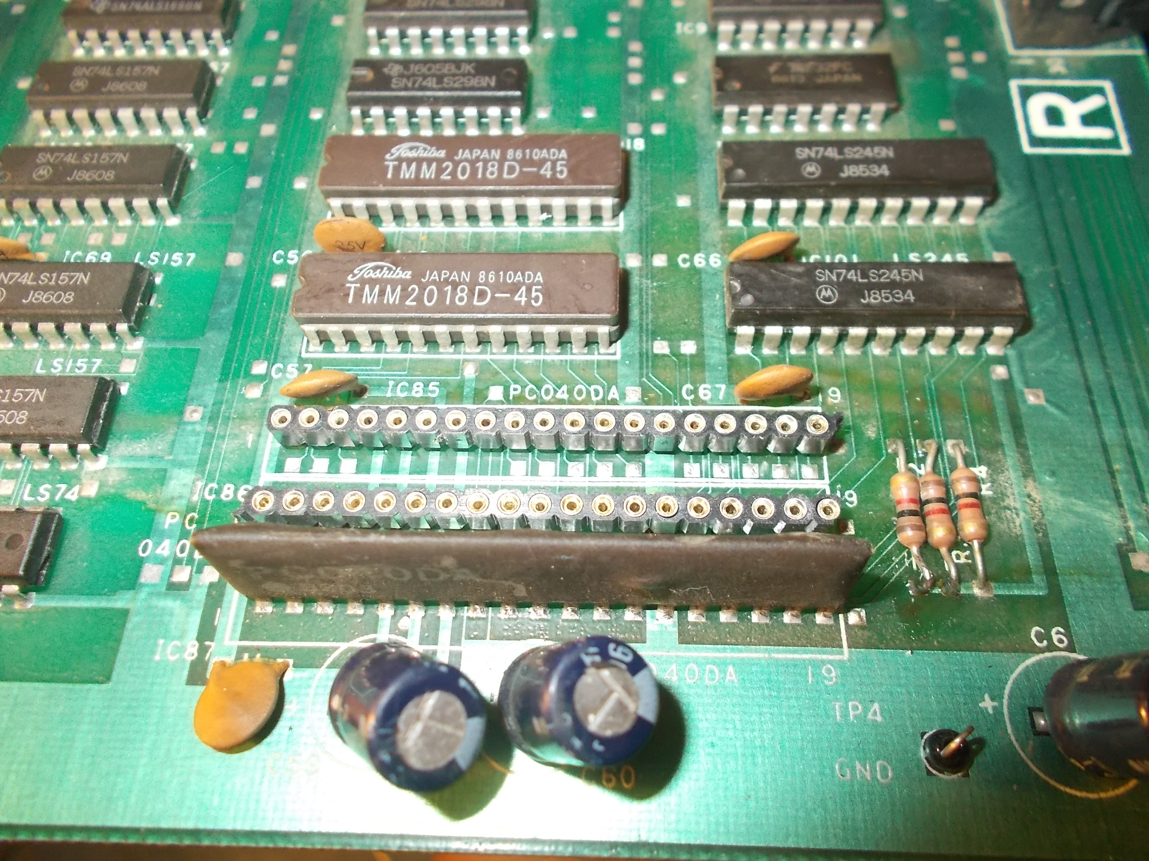
Game played blind, no RGB output, only SYNC was present on edge connector pins.Each colors is generated by a single ‘PC040DA’ custom (a 6 bit DAC)
Probing them revealed that pin 10 was stuck, this is the vertical blanking signal called /VBL on schematics:
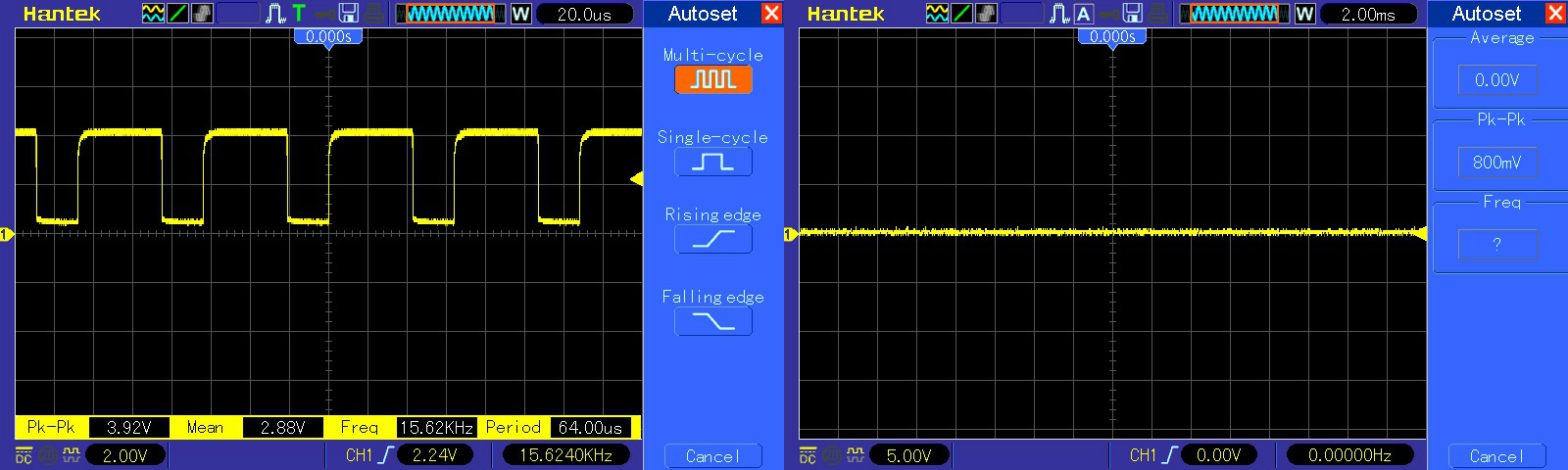
Tracing back the signal lead me to a counter 74LS163 @IC11:
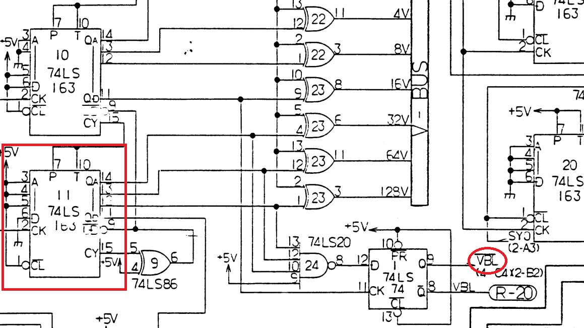
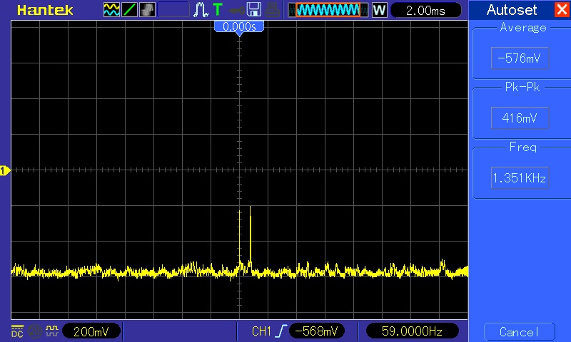
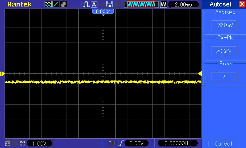
Clock on its pin 2 was present but all outputs were stuck low:
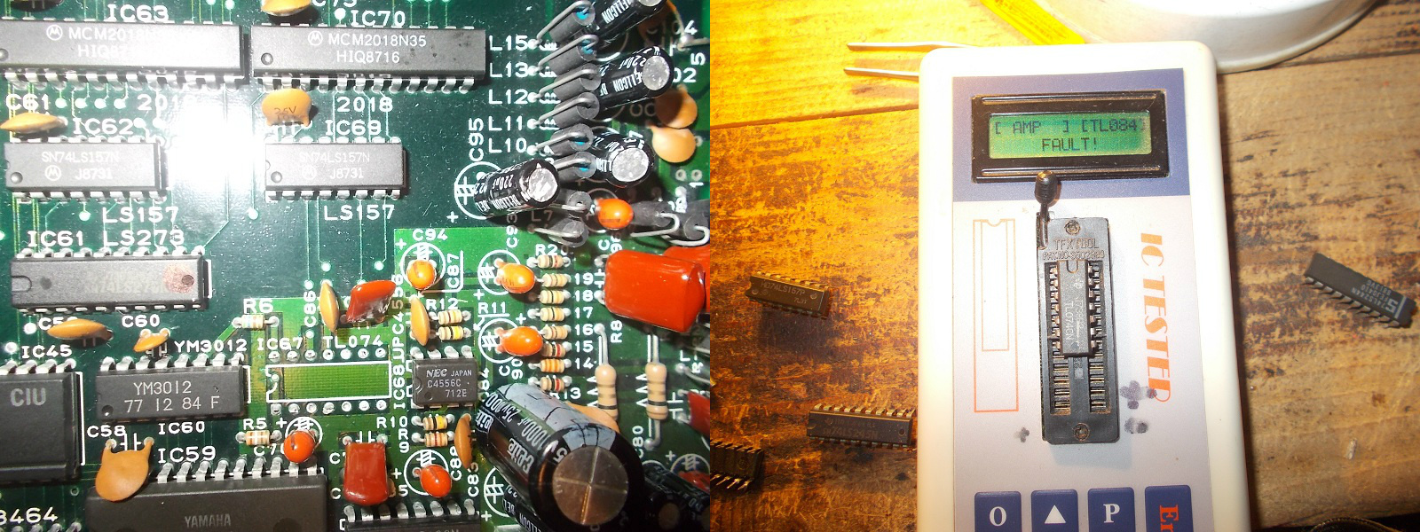
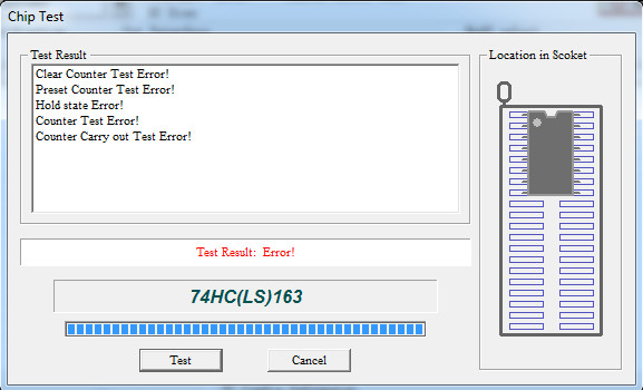
The IC failed the out-of-circuit test:
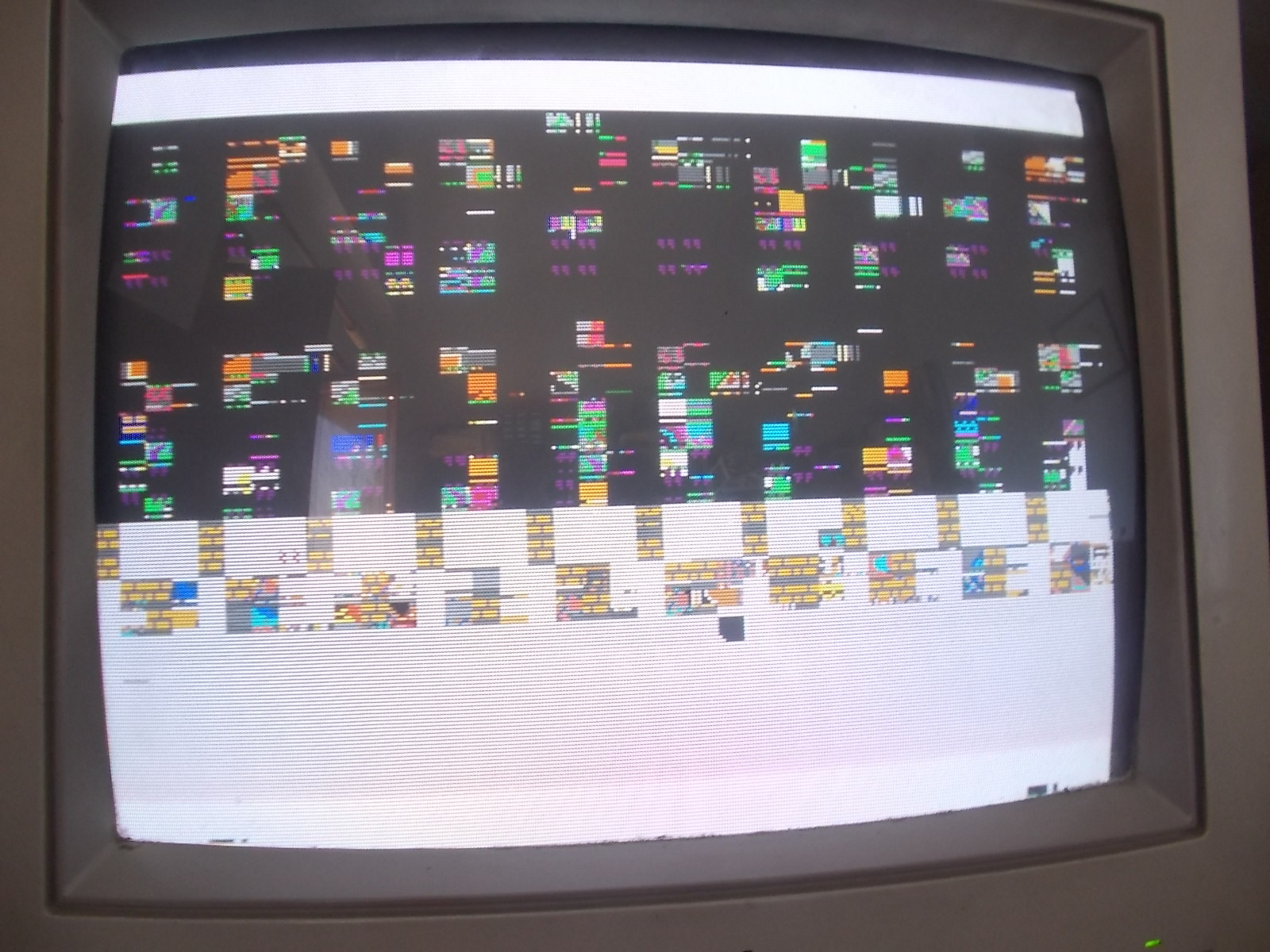
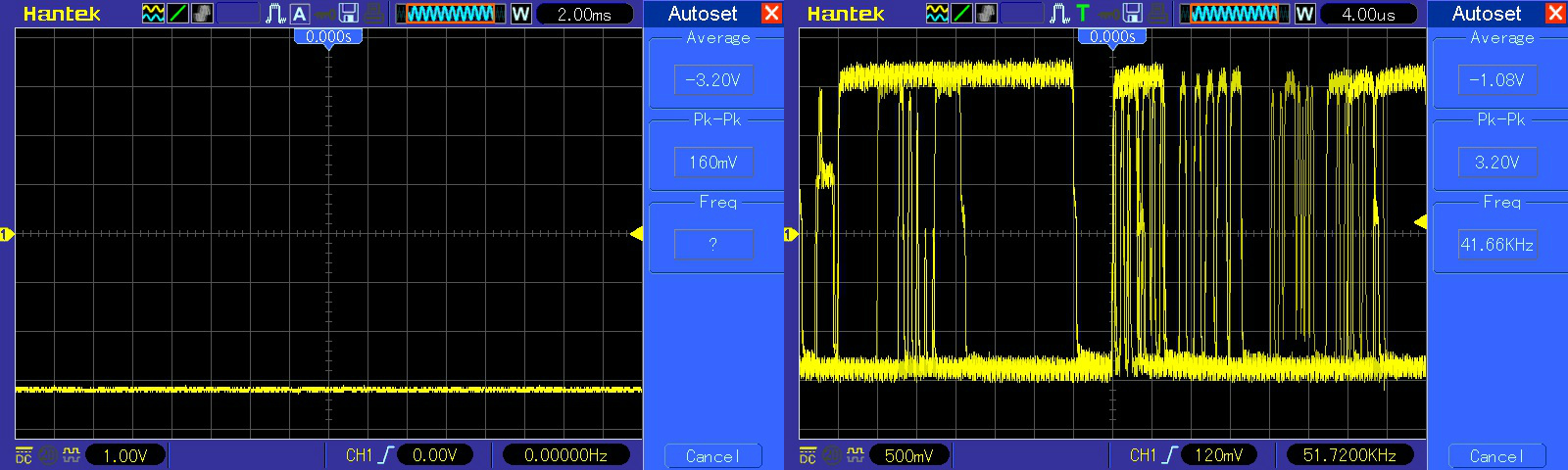
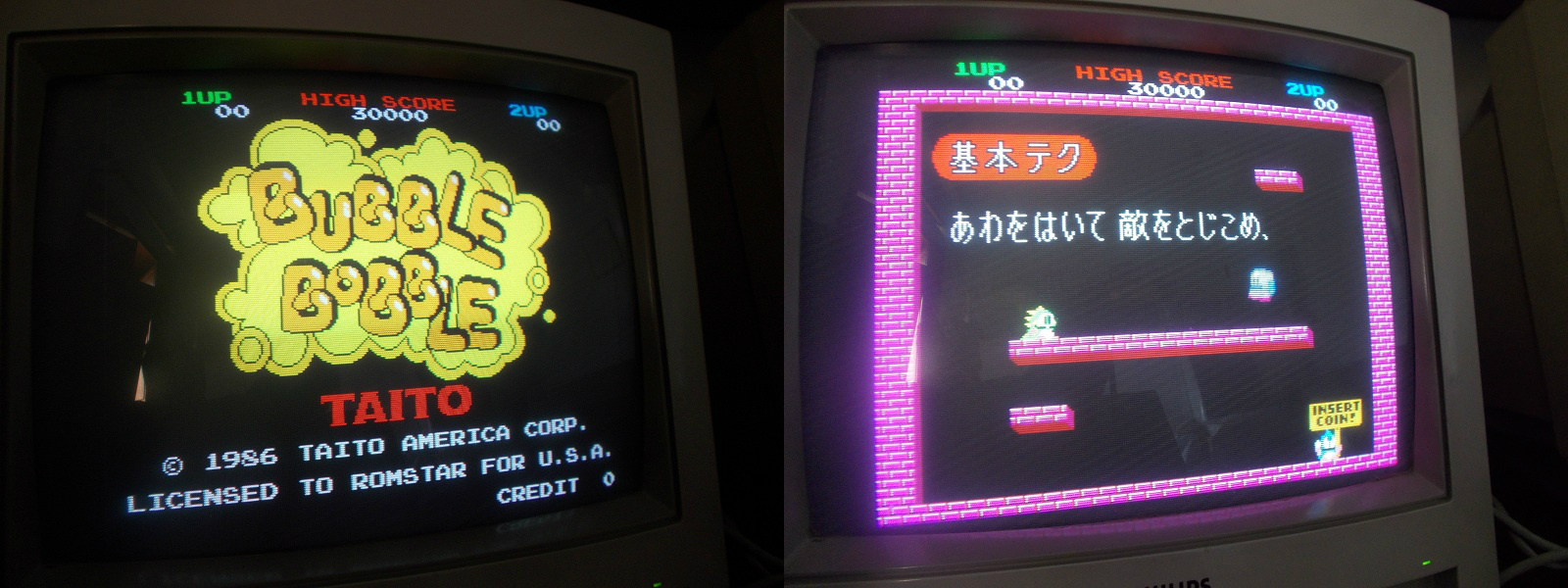
I replaced it and finally had output on video but all was displayed with the only red color, green and blue were missing at all:
I checked the two involved PC040DA customs @IC85 and IC86 and found that their output pin 3 was clearly dead compared with the active one of red color:
I removed them and installed sockets:
I took the donor parts from a Rastan PCB and installed them:
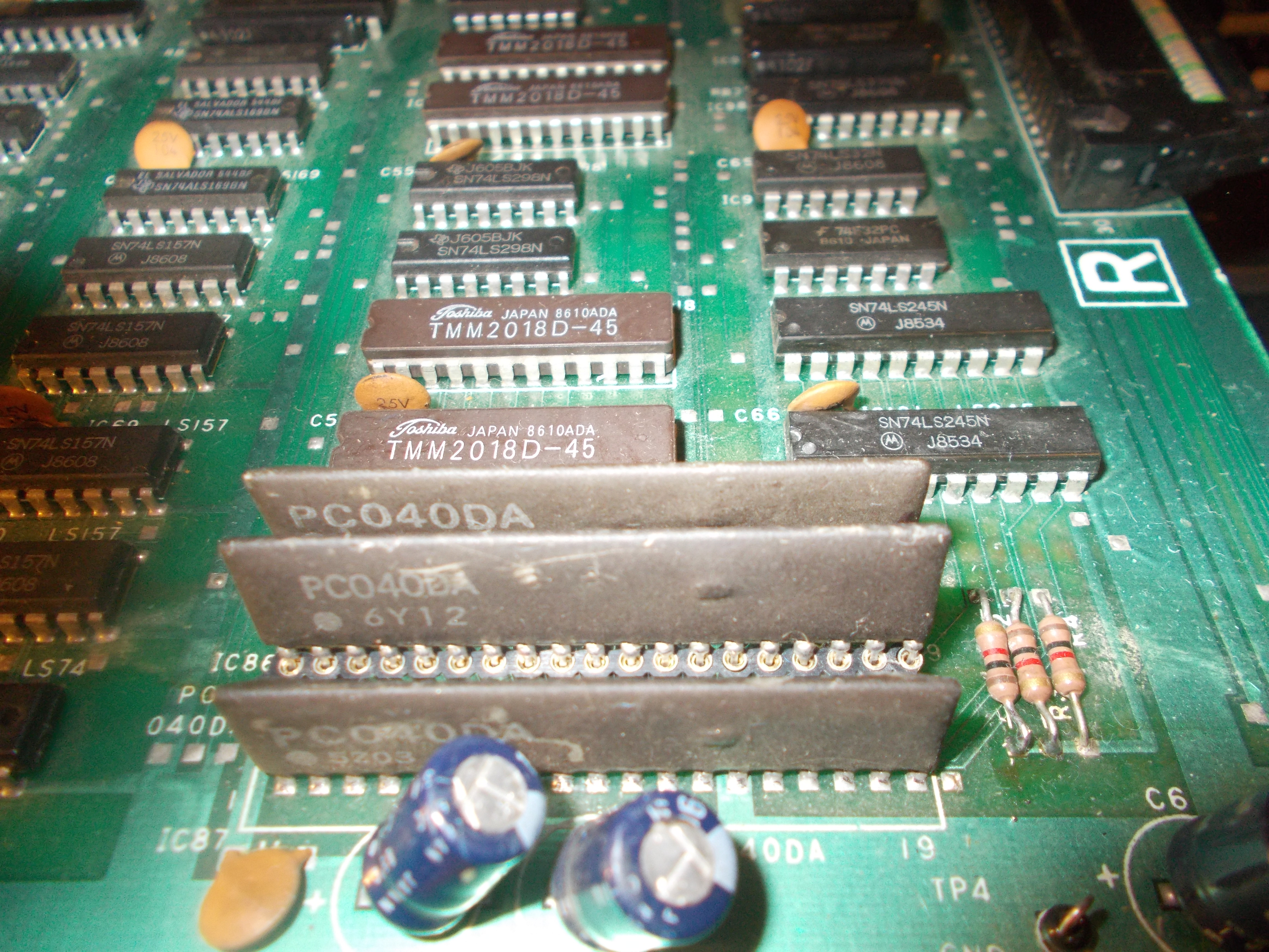
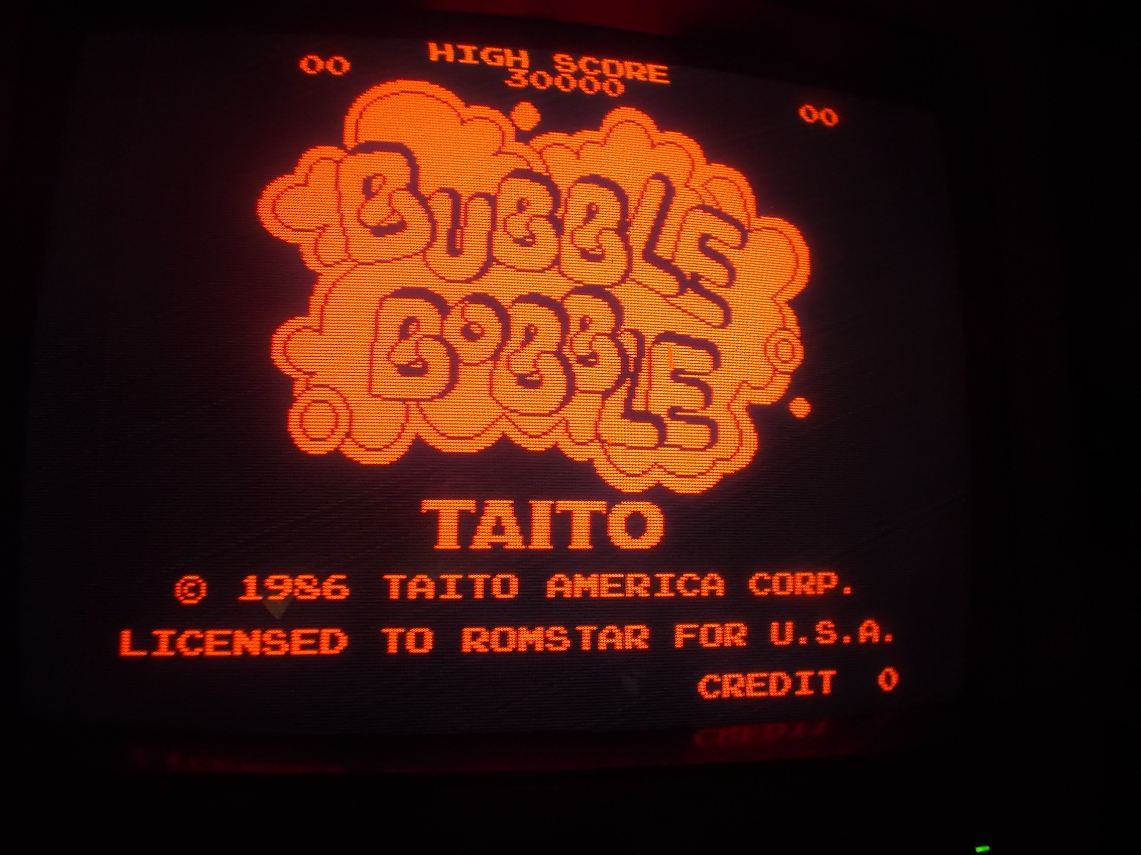
Colors were restored and board 100% fixed.
P.S.
‘PC040DA’ DAC could be the next candidate for a reproduction although someone has already did it:
https://www.gamoover.net/Forums/index.php?PHPSESSID=f9cba7f099937c197dceb458d0b6a897&topic=27336.0