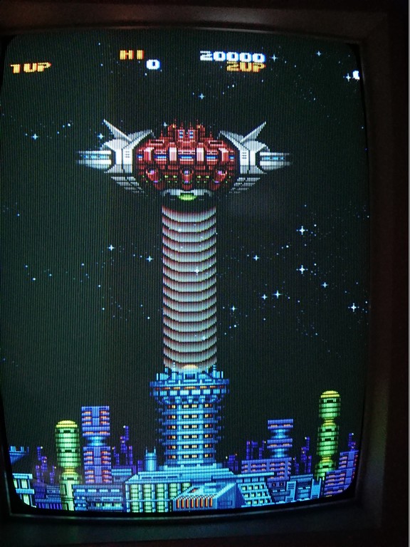
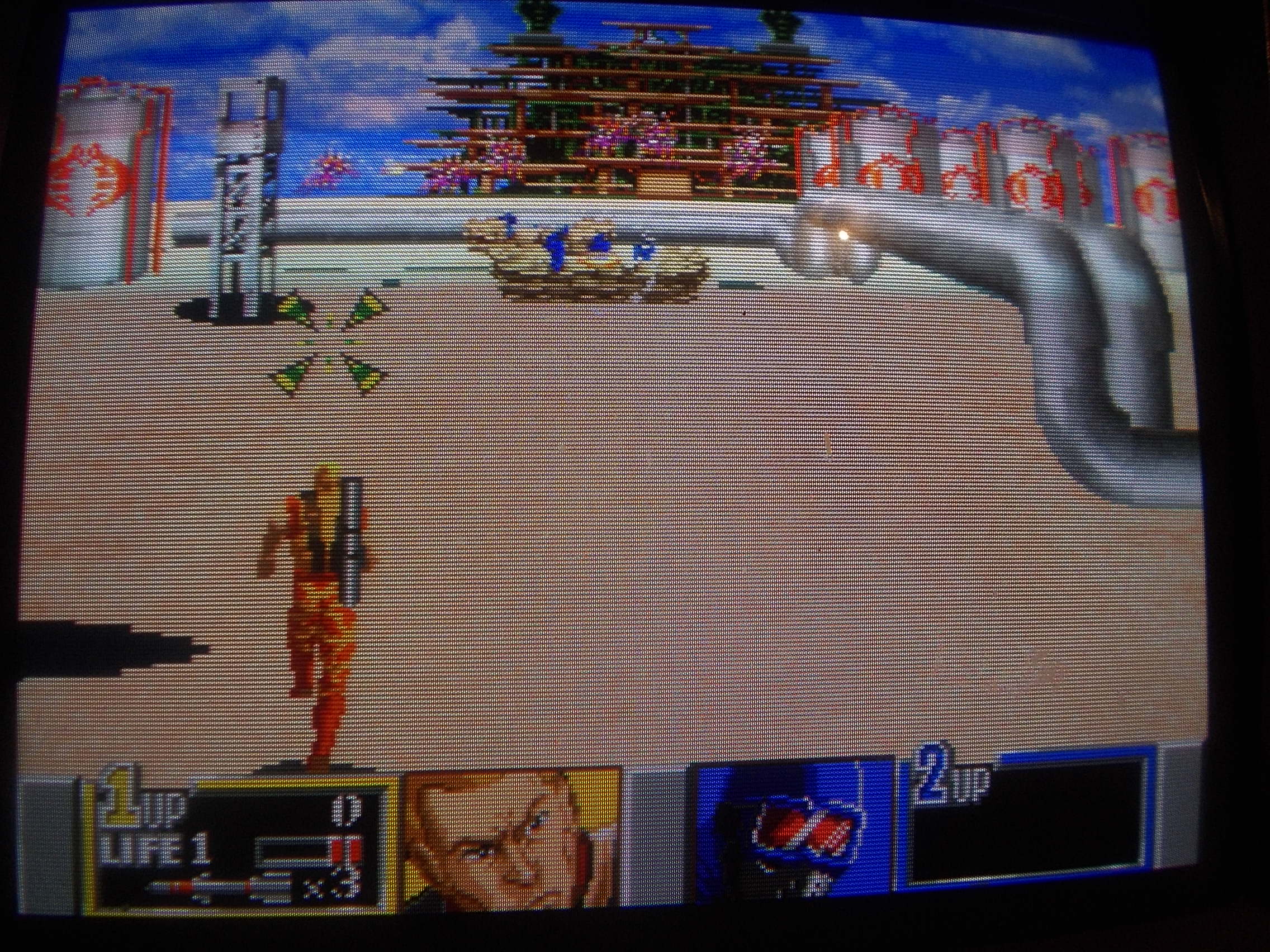
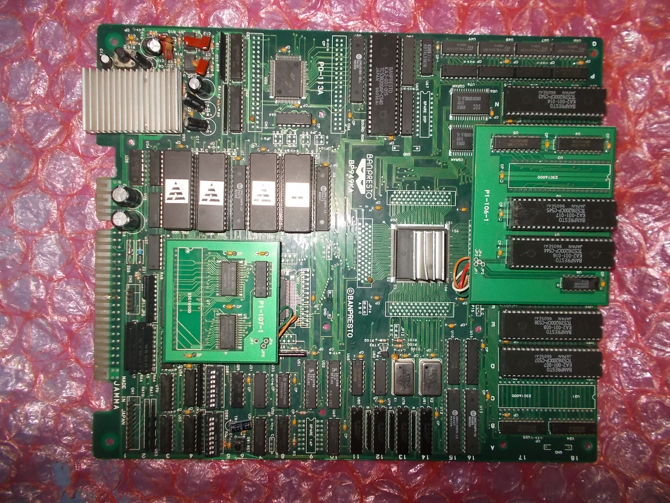
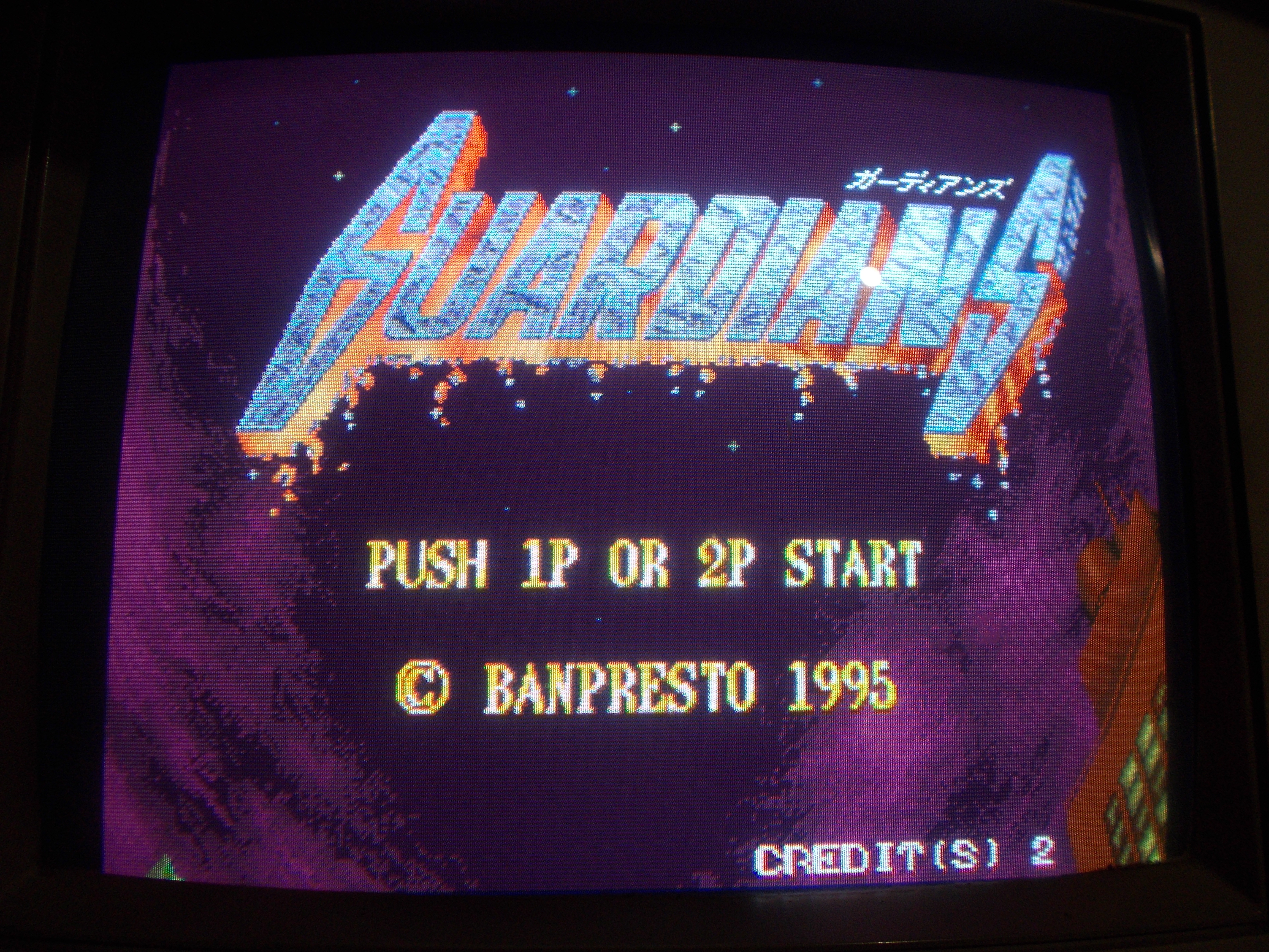
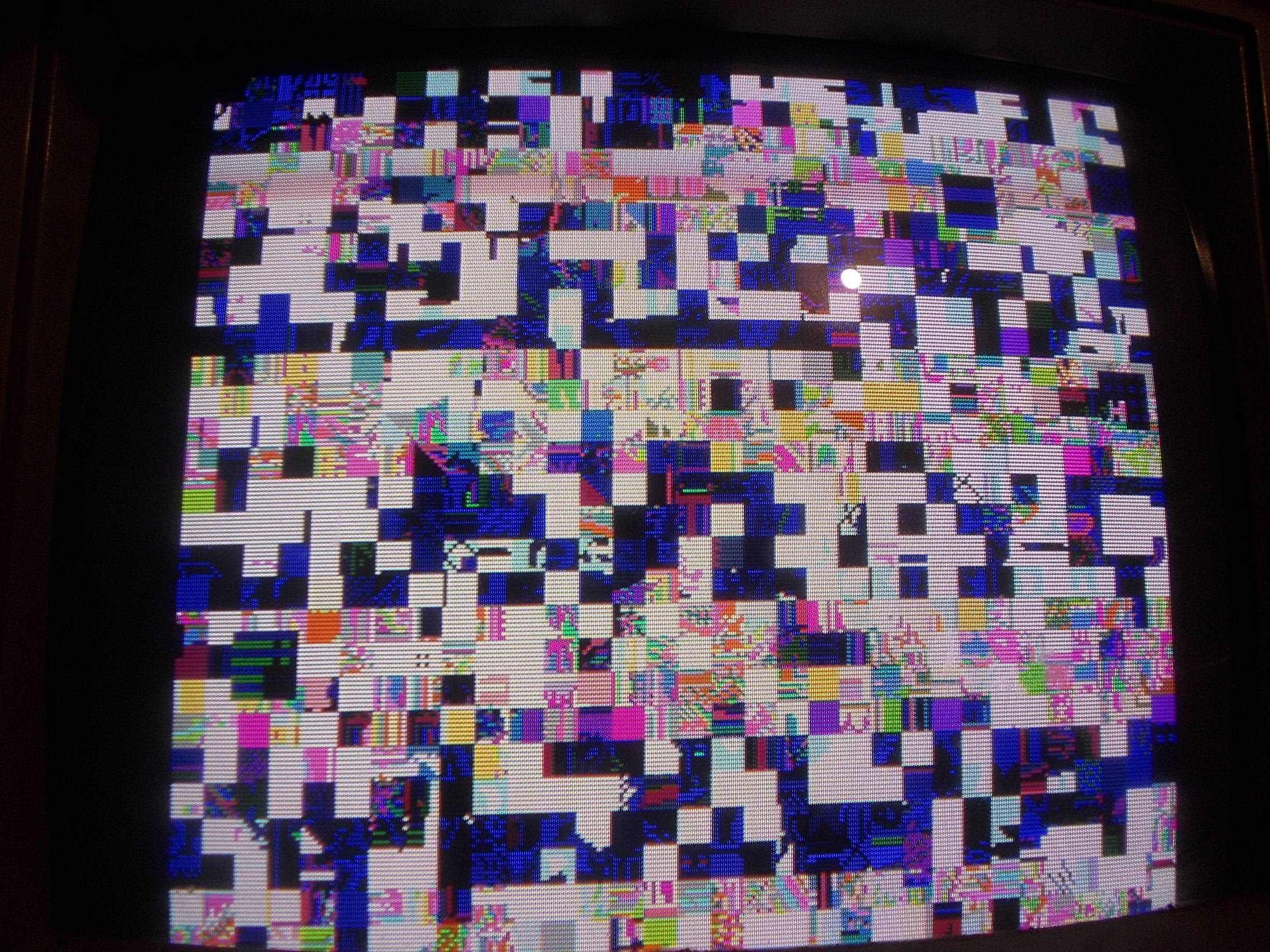
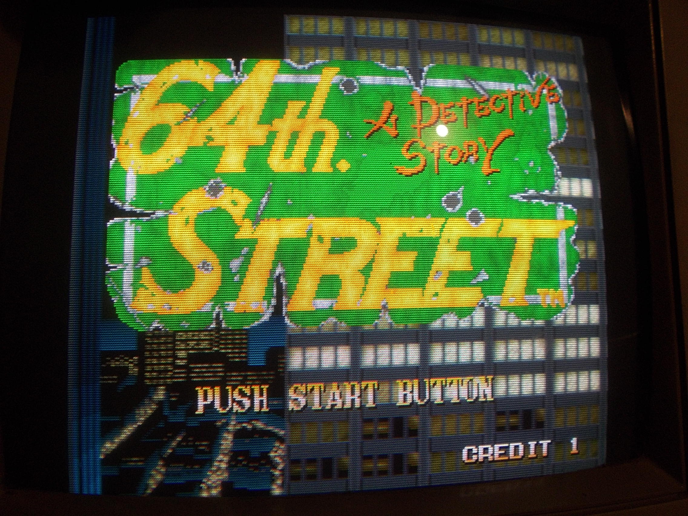
Bought this game for personal collection but despite having declared working it had some graphic faults.
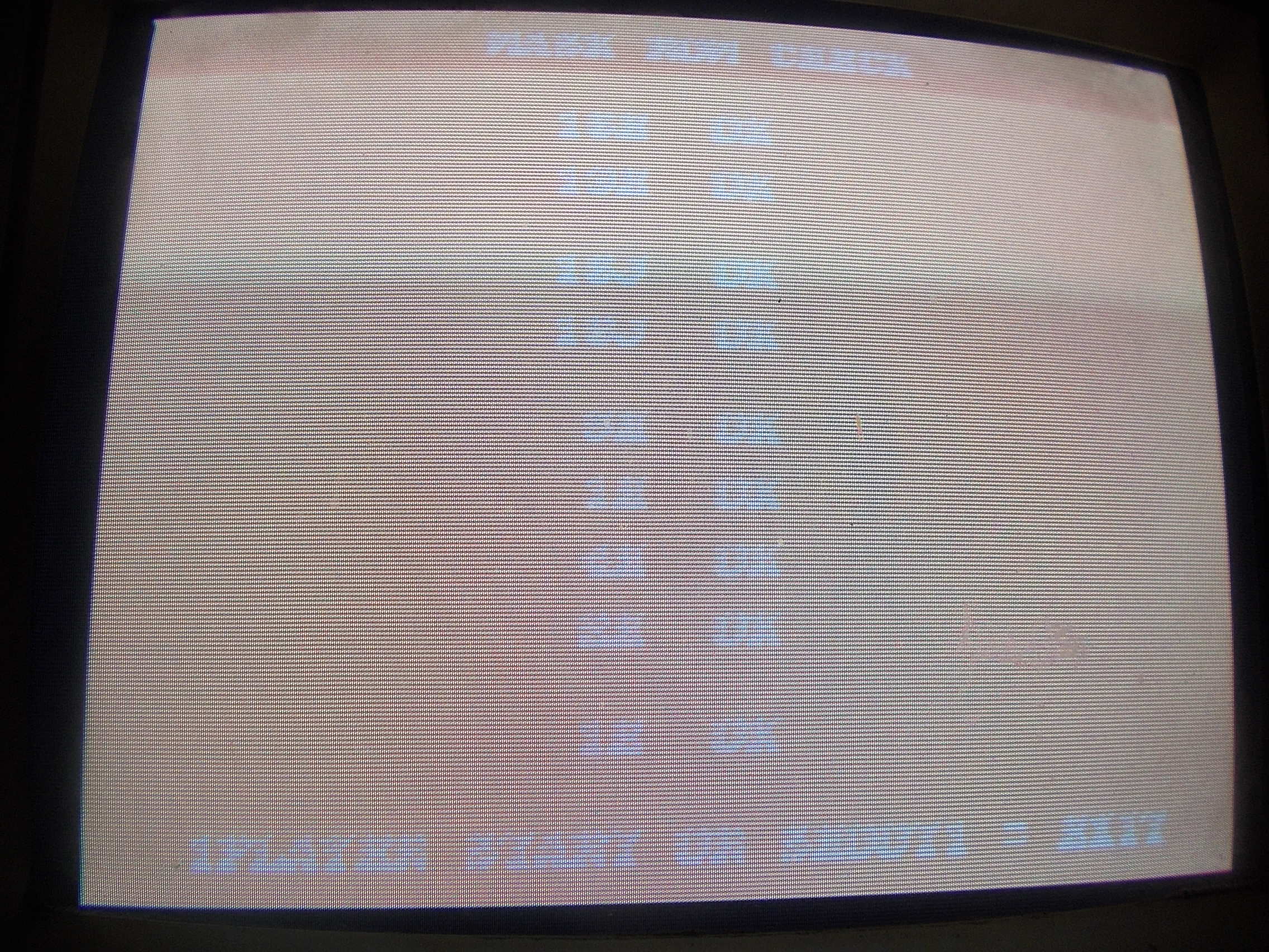
In particular the intro had blockly graphics and generally lacked shade of colours. The gameplay was in general fine at least for the first two levels.
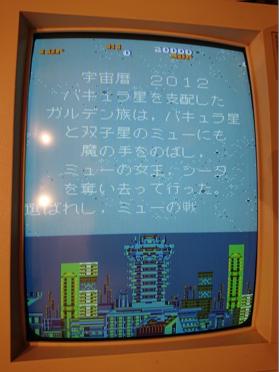
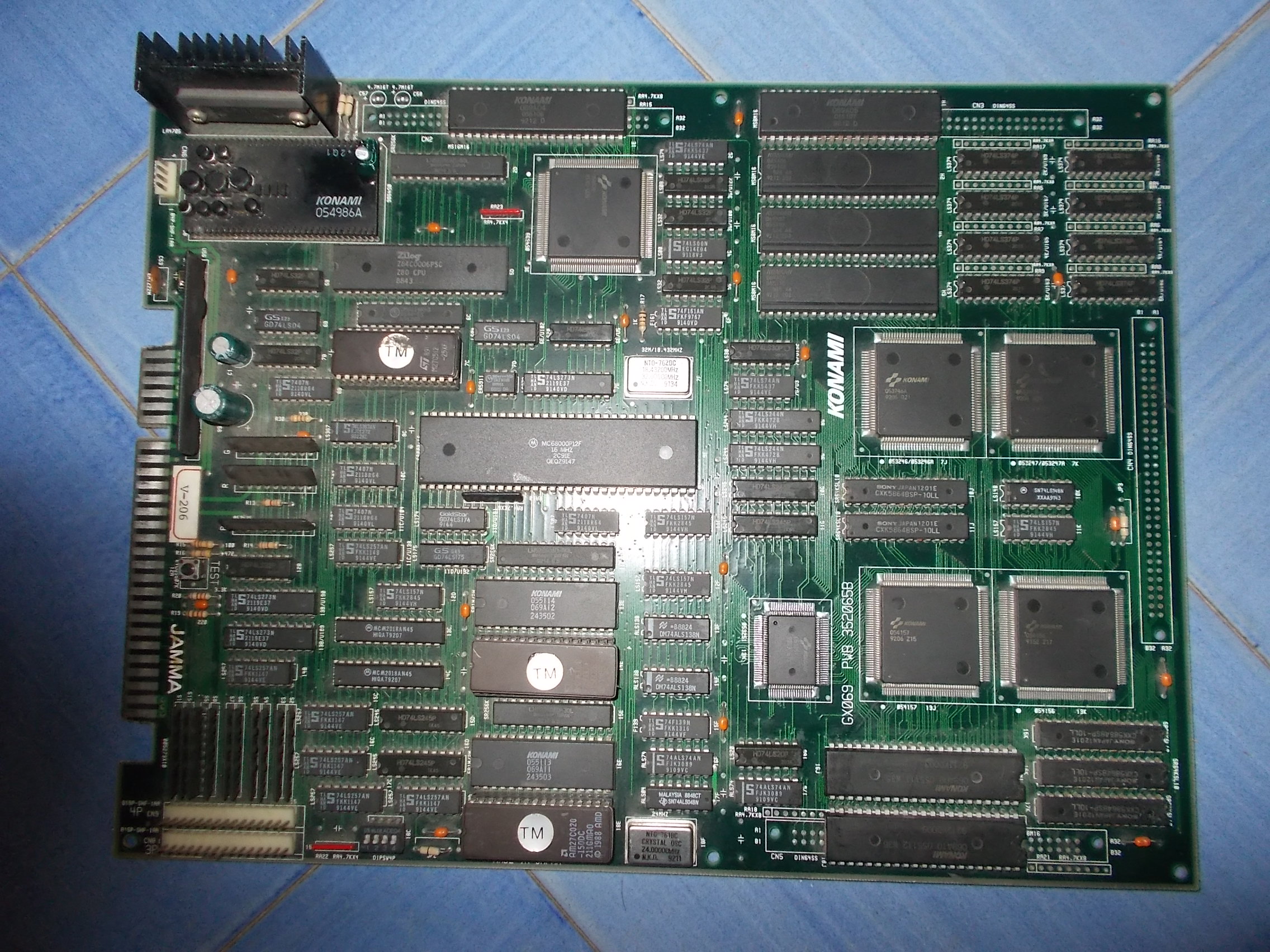
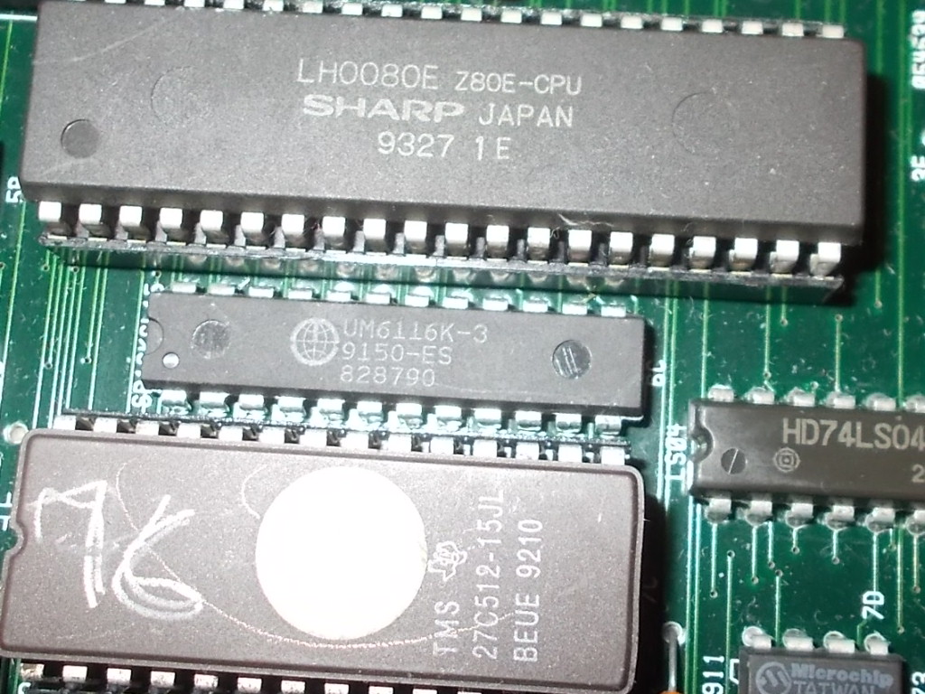
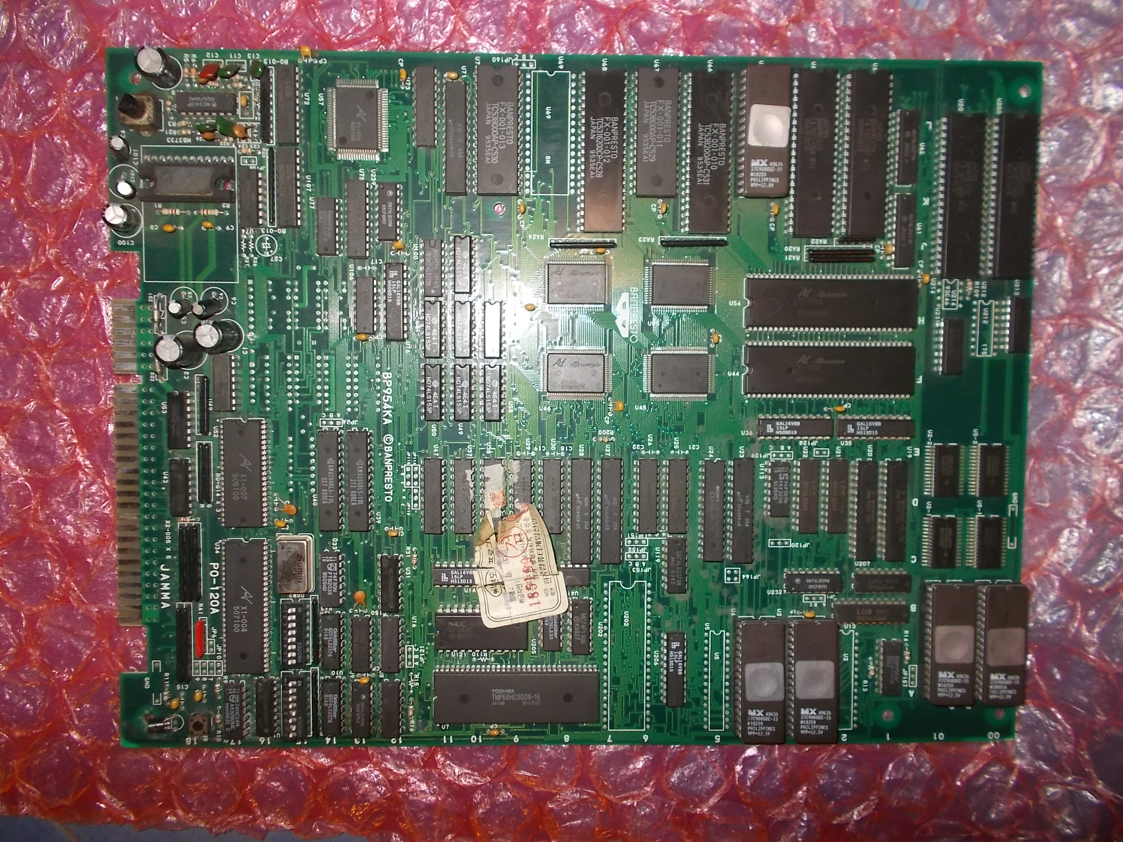
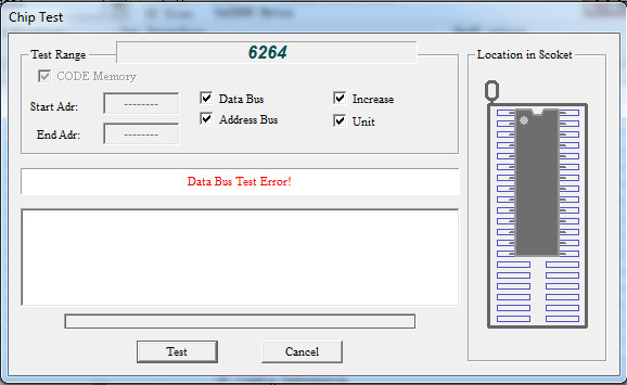
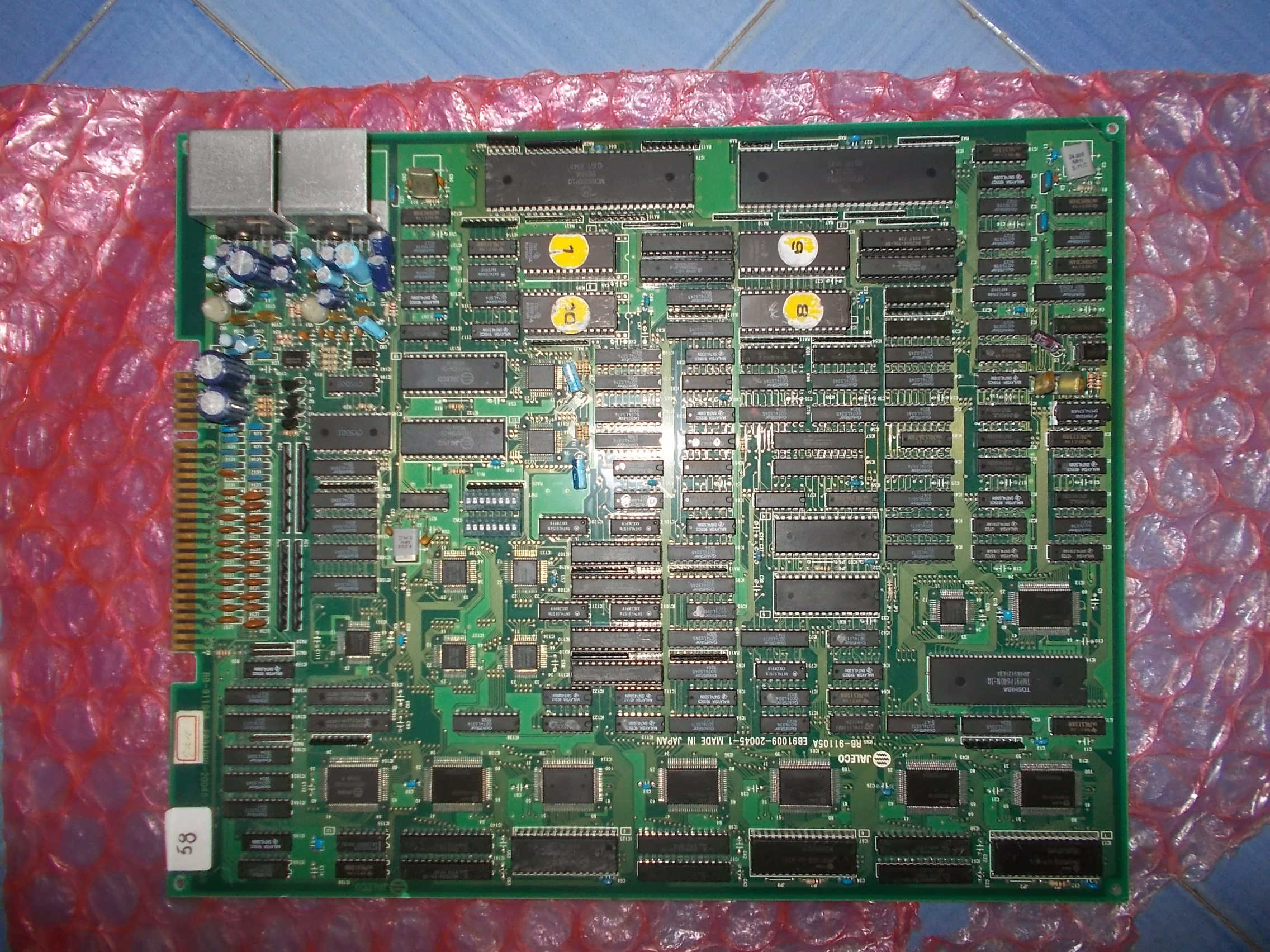
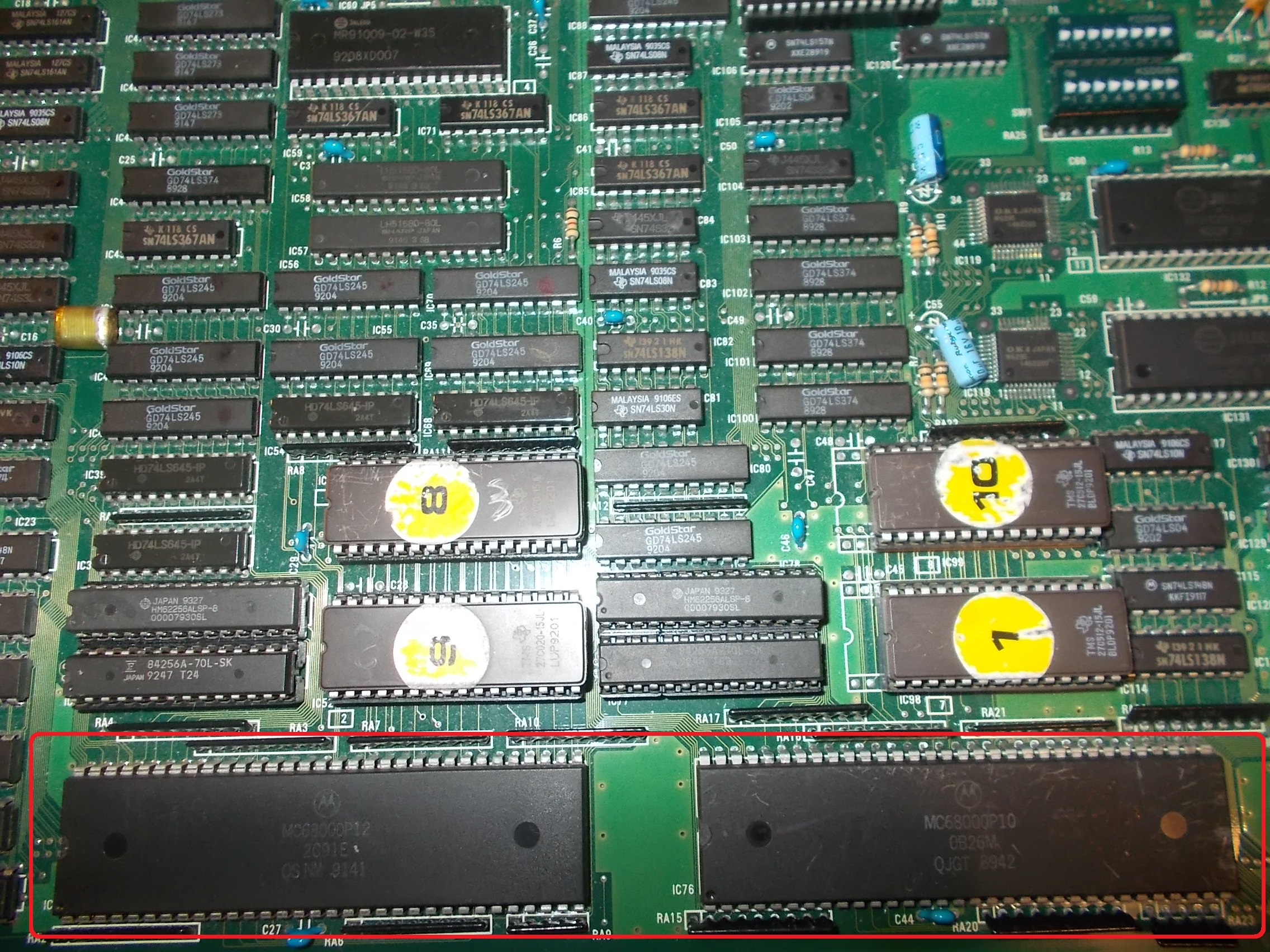
I started to check maskroms and found LD13 and LD15 which handled the tiles of the intro. Maskroms were tested good on the programmer.
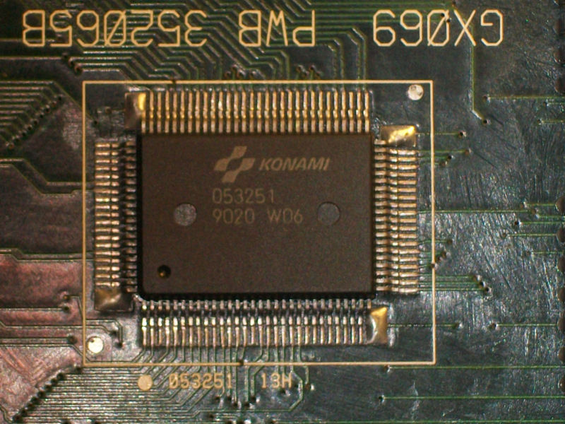
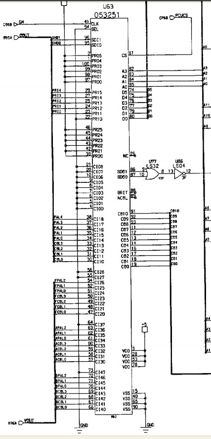
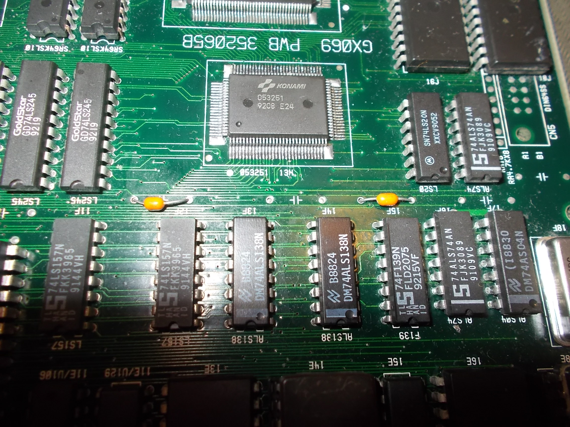
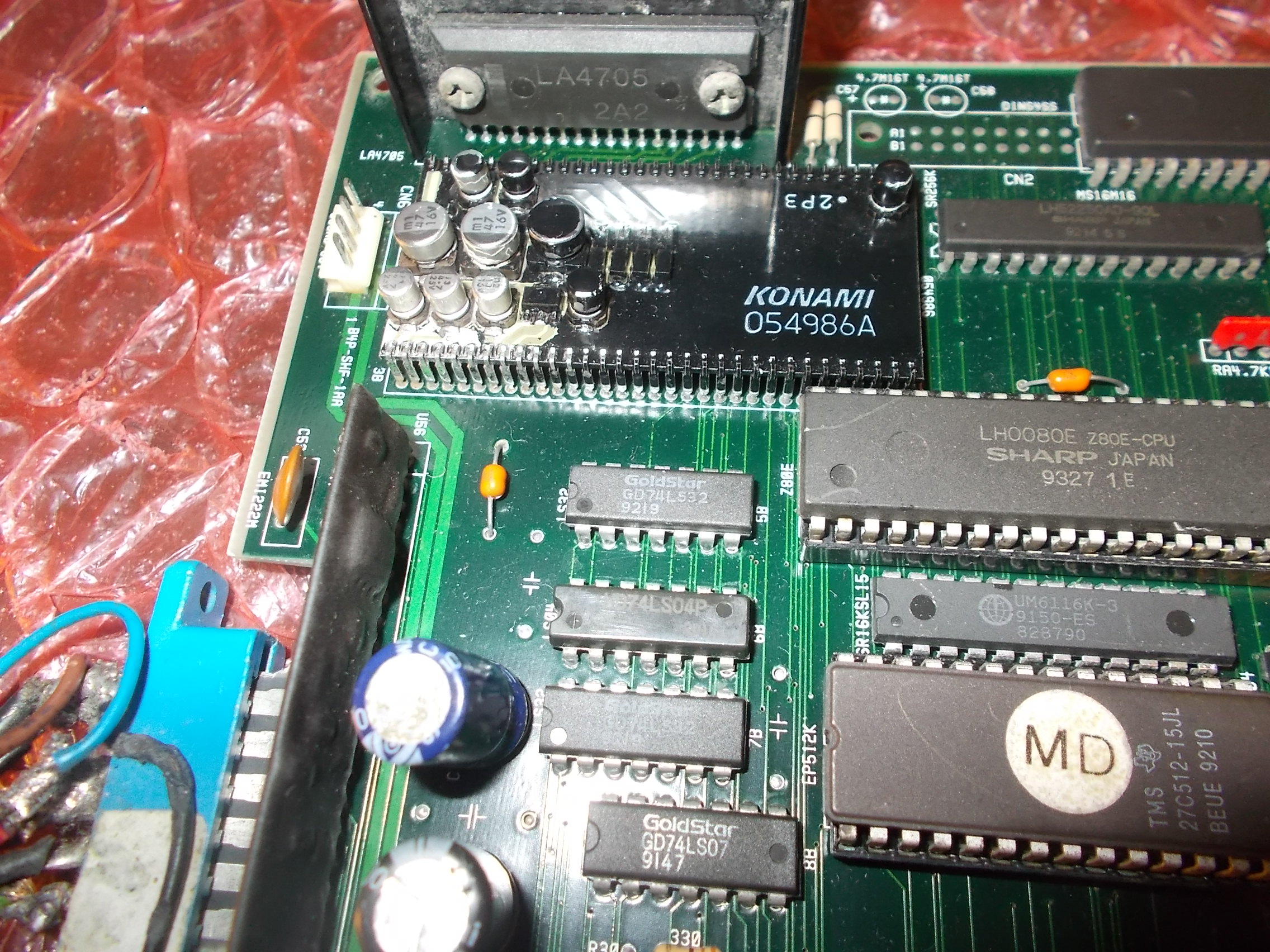
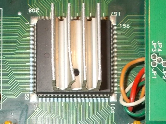
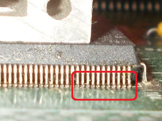
Data pins went to a 86s100 custom chip which usually is not very reliable ( see bottom right of the pic below)
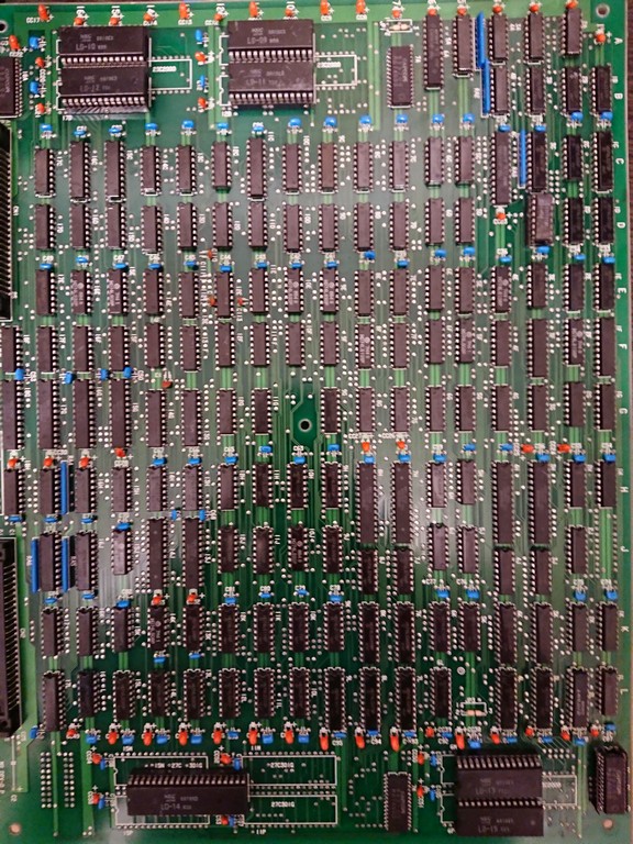
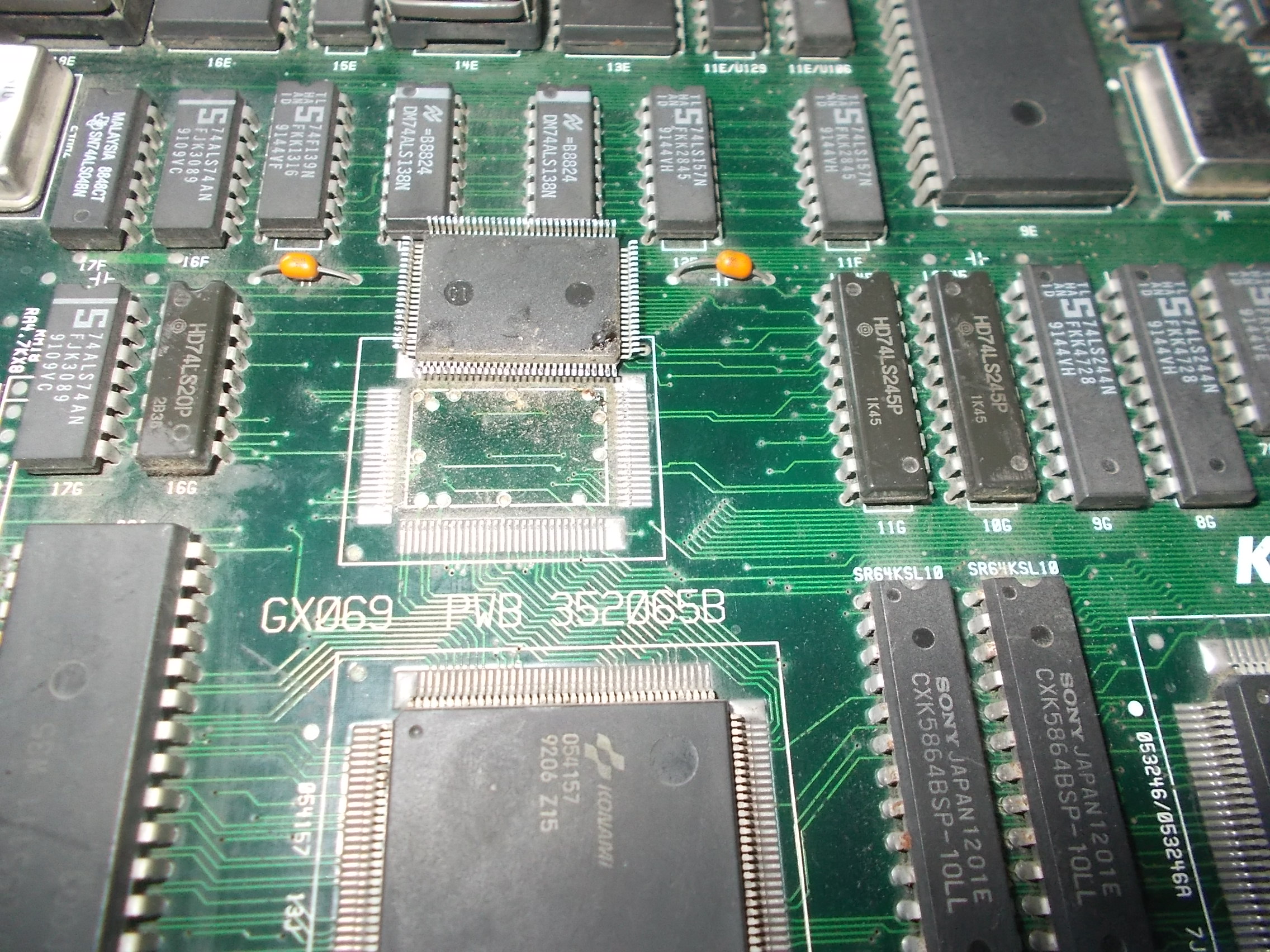
At this point I decided to put a socket and change it with another one I took years ago from Poker Ladies.
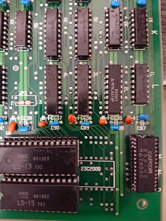
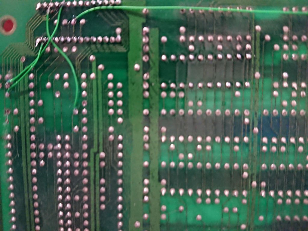
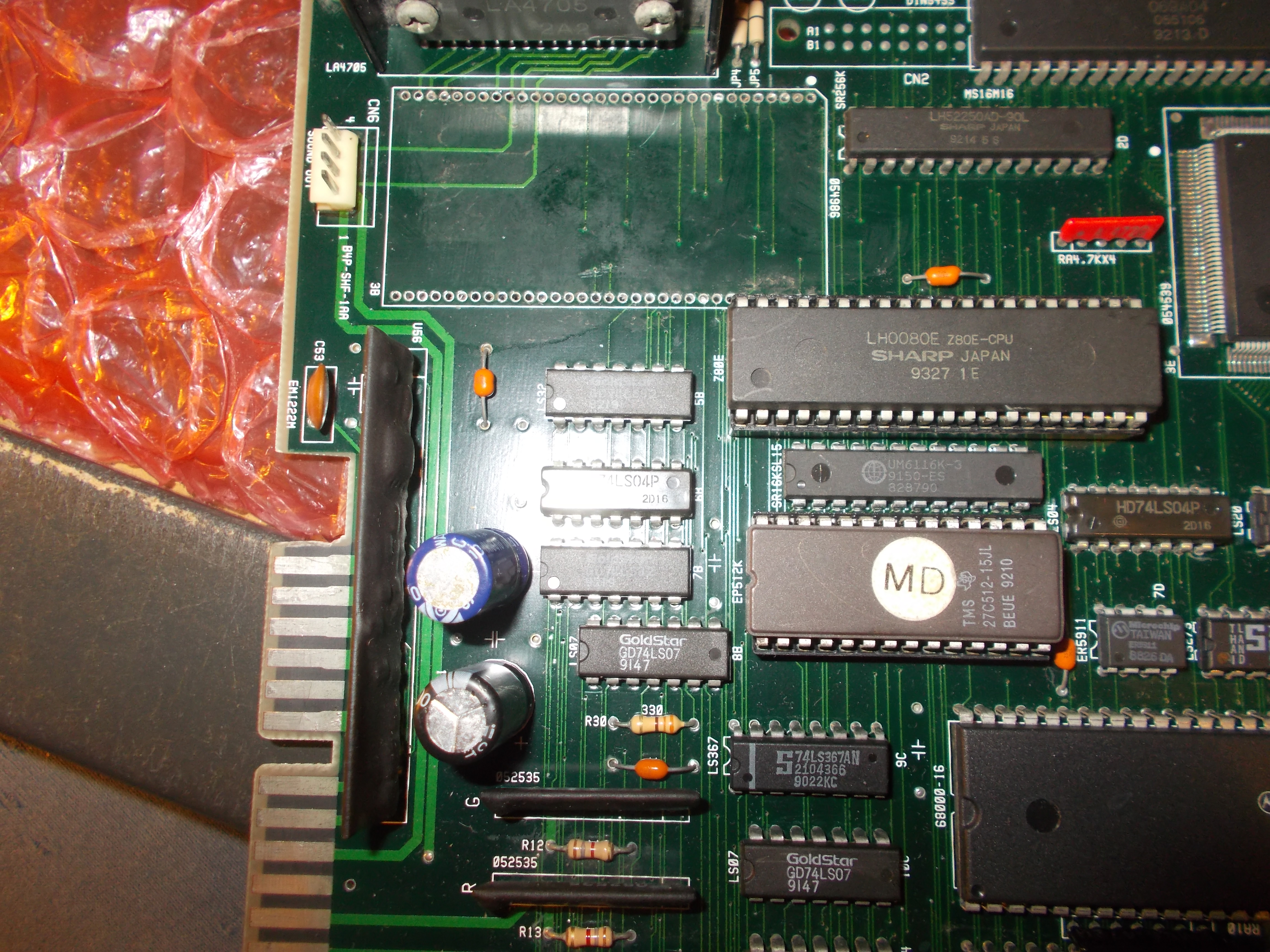
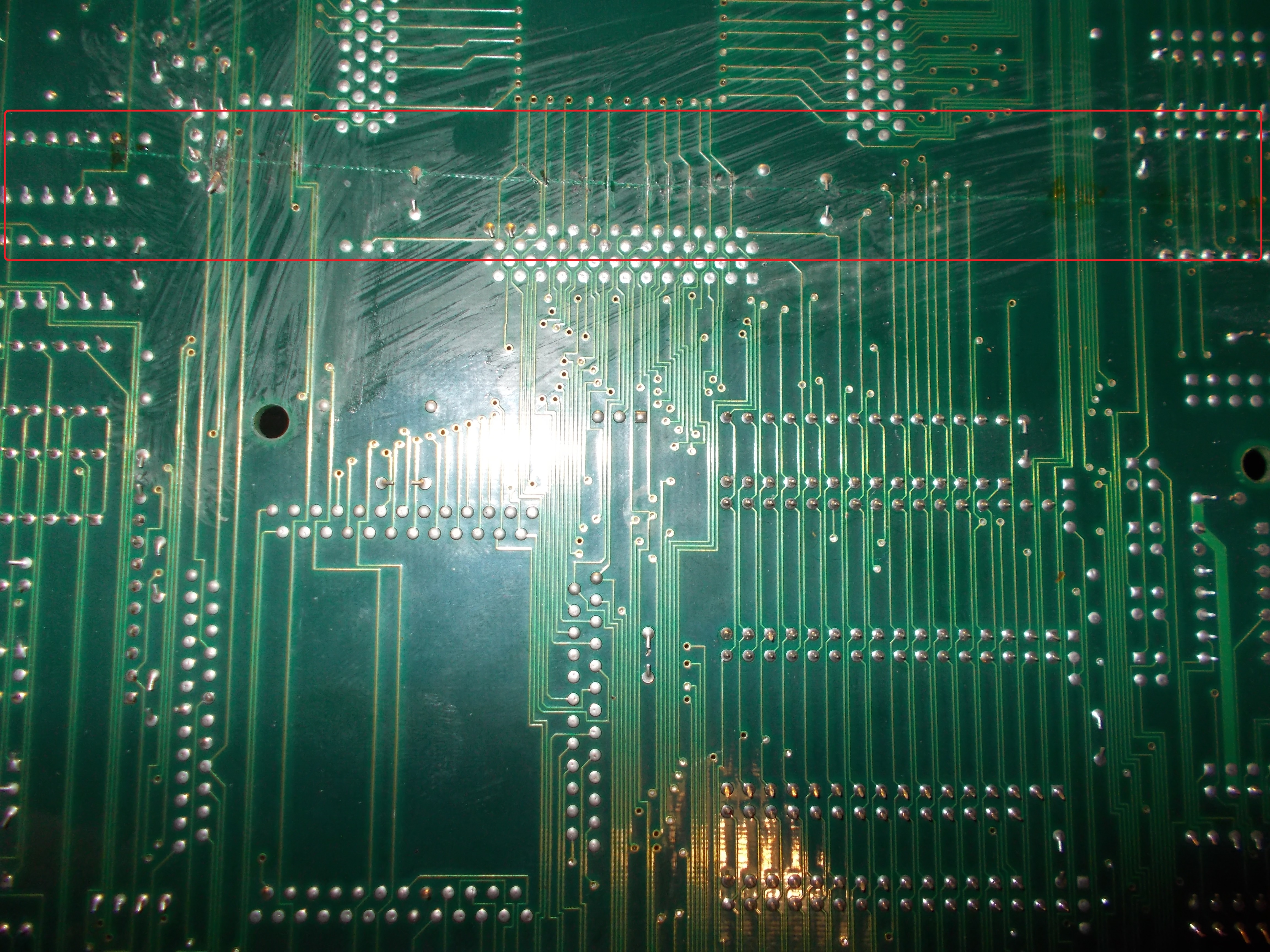
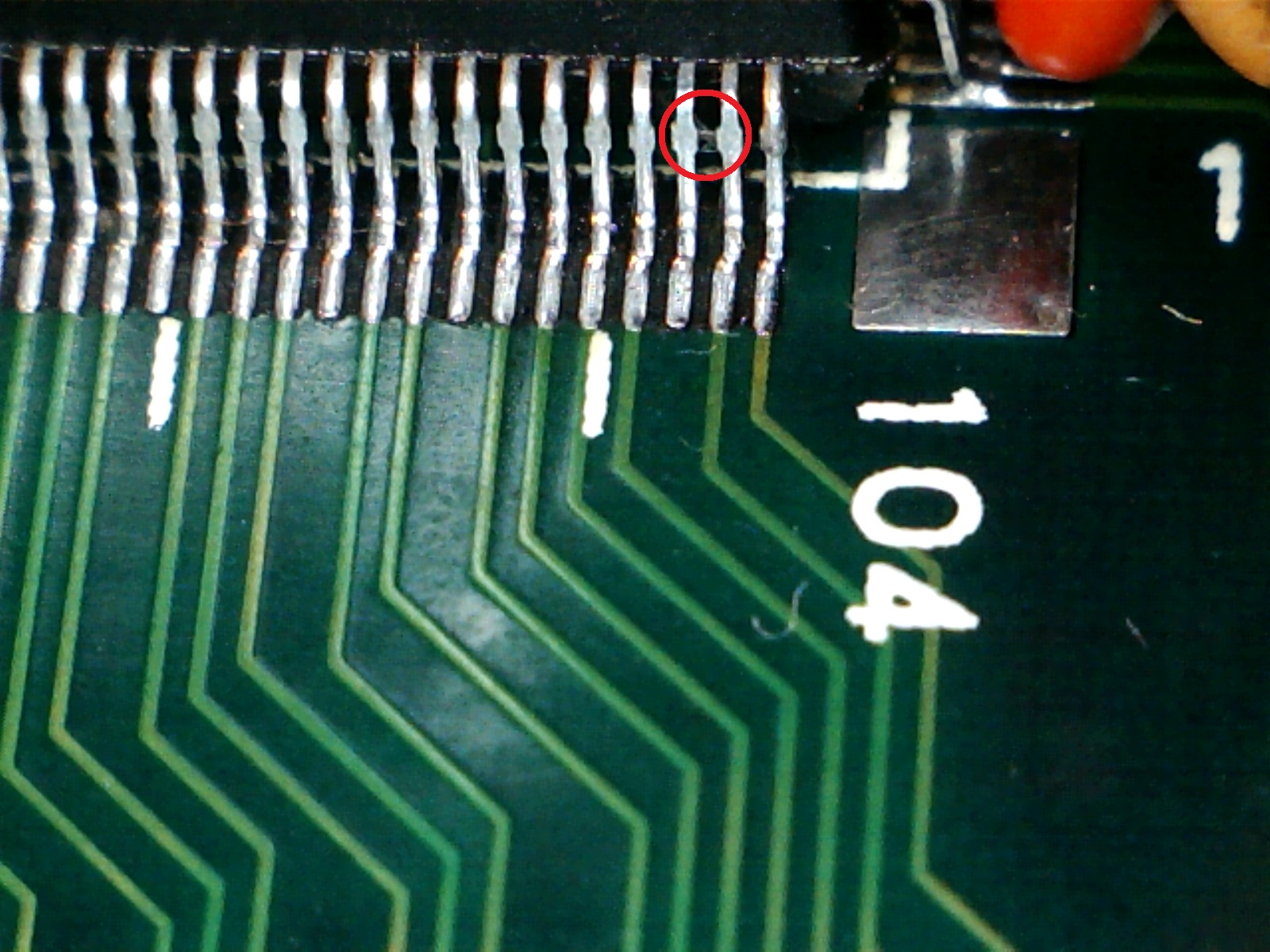
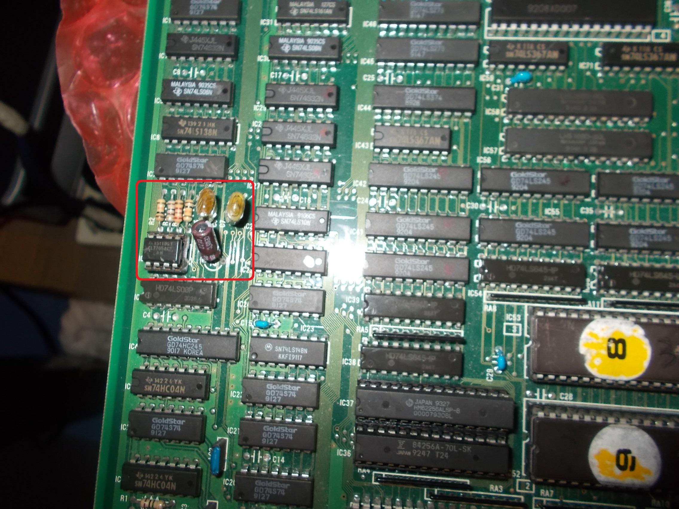
Unfortunately the defect was still there but after another look underneath the board and I saw some borken traces which connected the custom to a 74ls273.
There were 3 traces severed but still the graphics were not fixed at all without a sign of improvement.
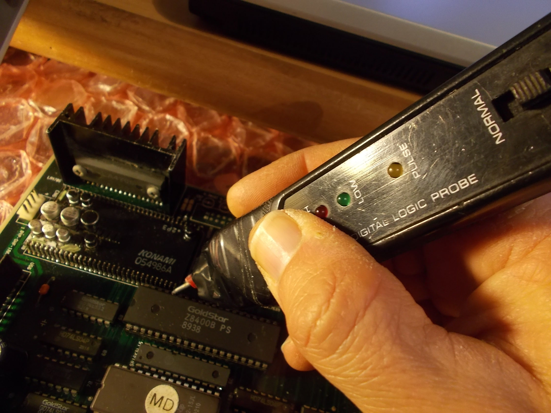
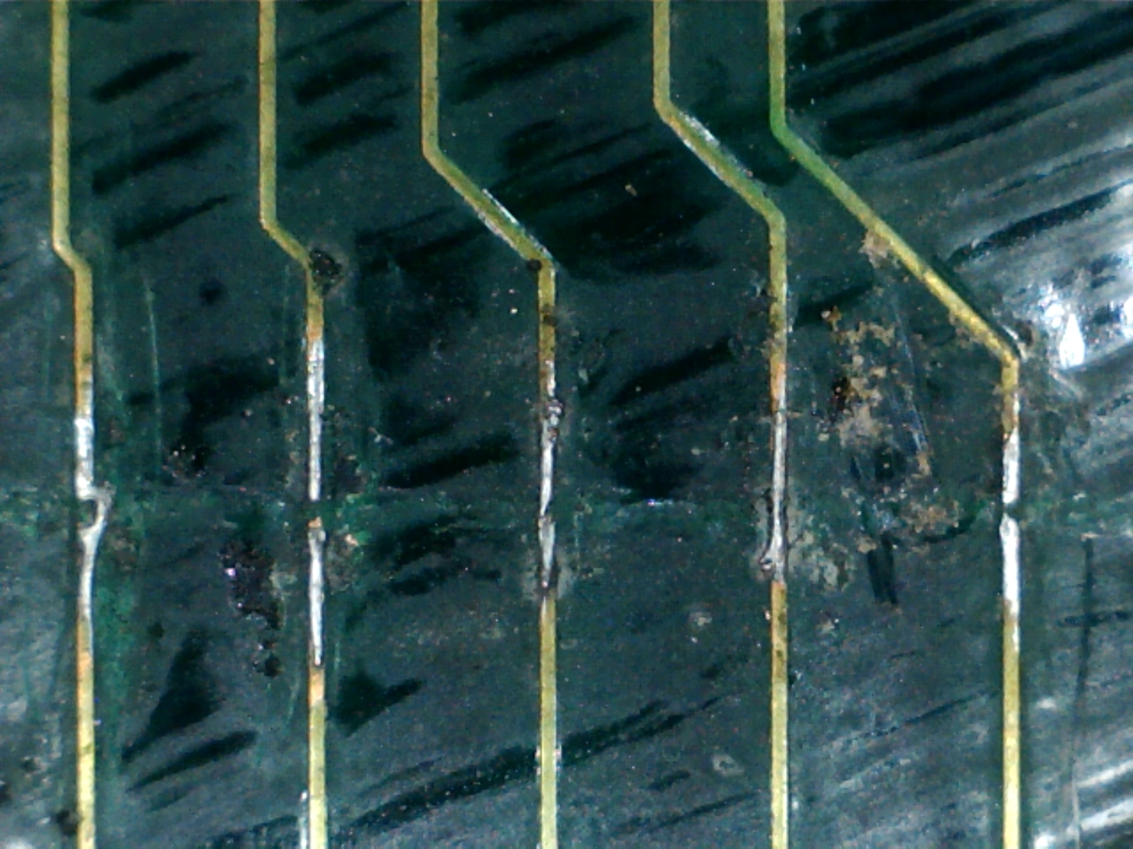
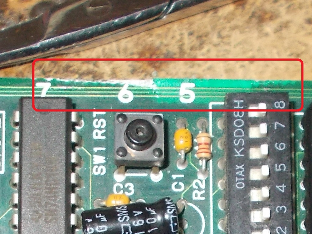
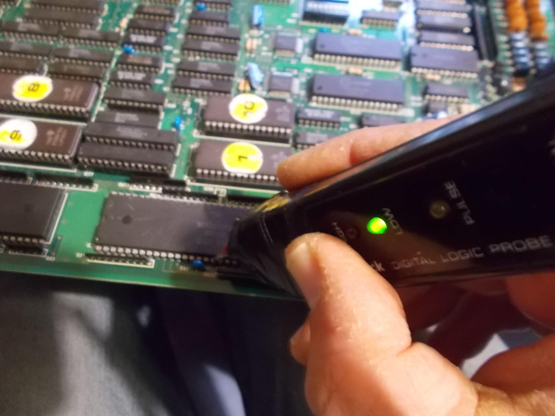
At this point I started to probe all the other ttl of the video board until I noticed a floating data pin of a 74ls273 which led again to the custom.
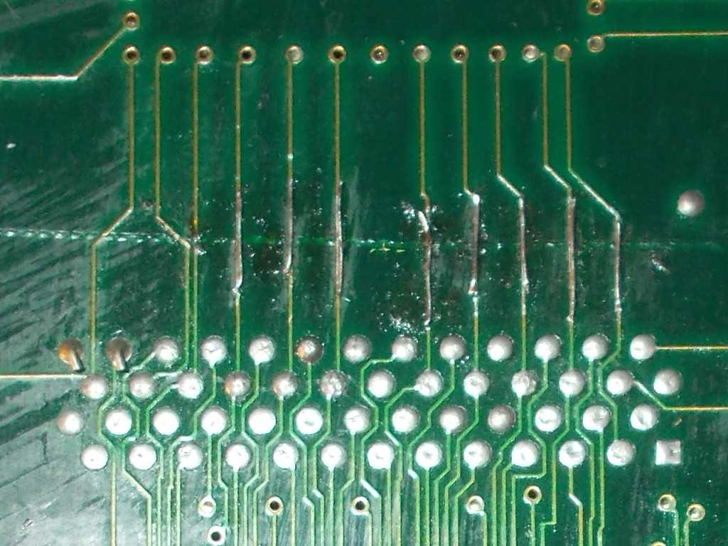
The trace interrupted at some point but I could not see any visible scratch until I noticed it near a silscreened text H1, not easy to find at all
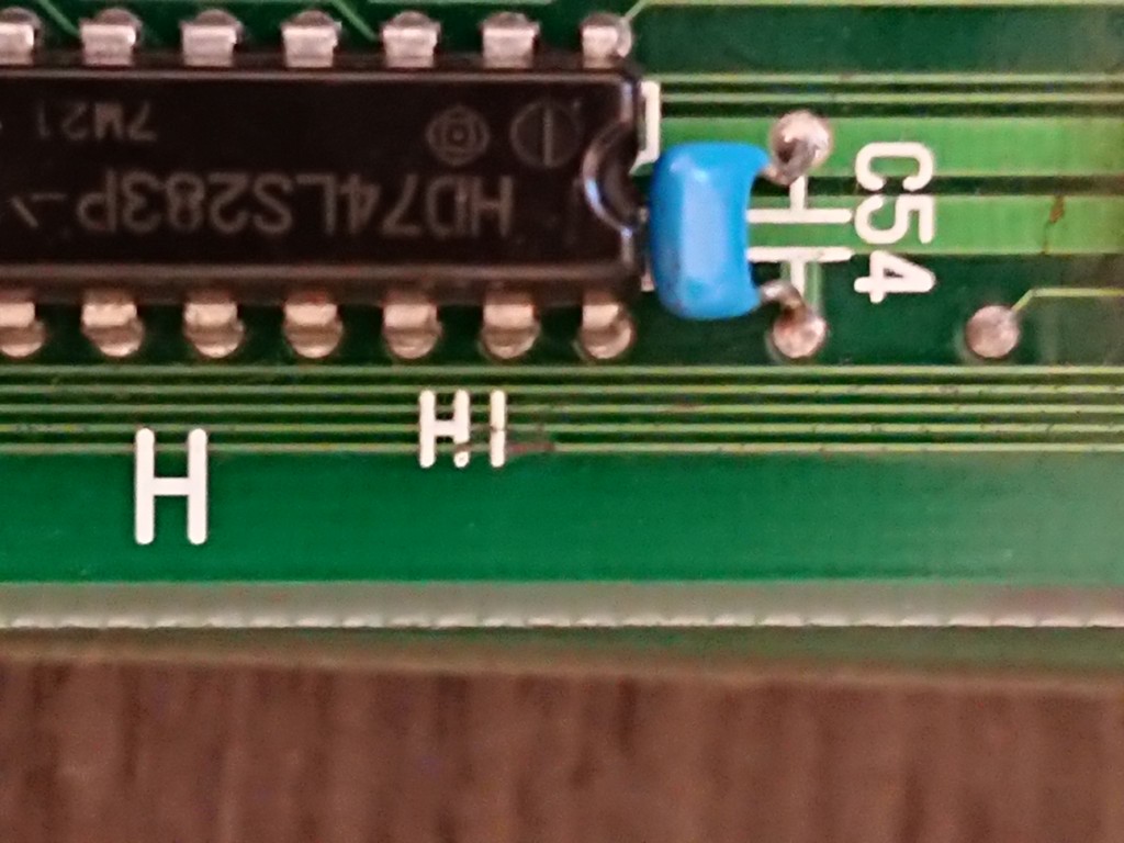
After repairing this track the game was fully restored