PCB Repair LogsComments Off on The New Zealand Story repair log #5
Aug022019
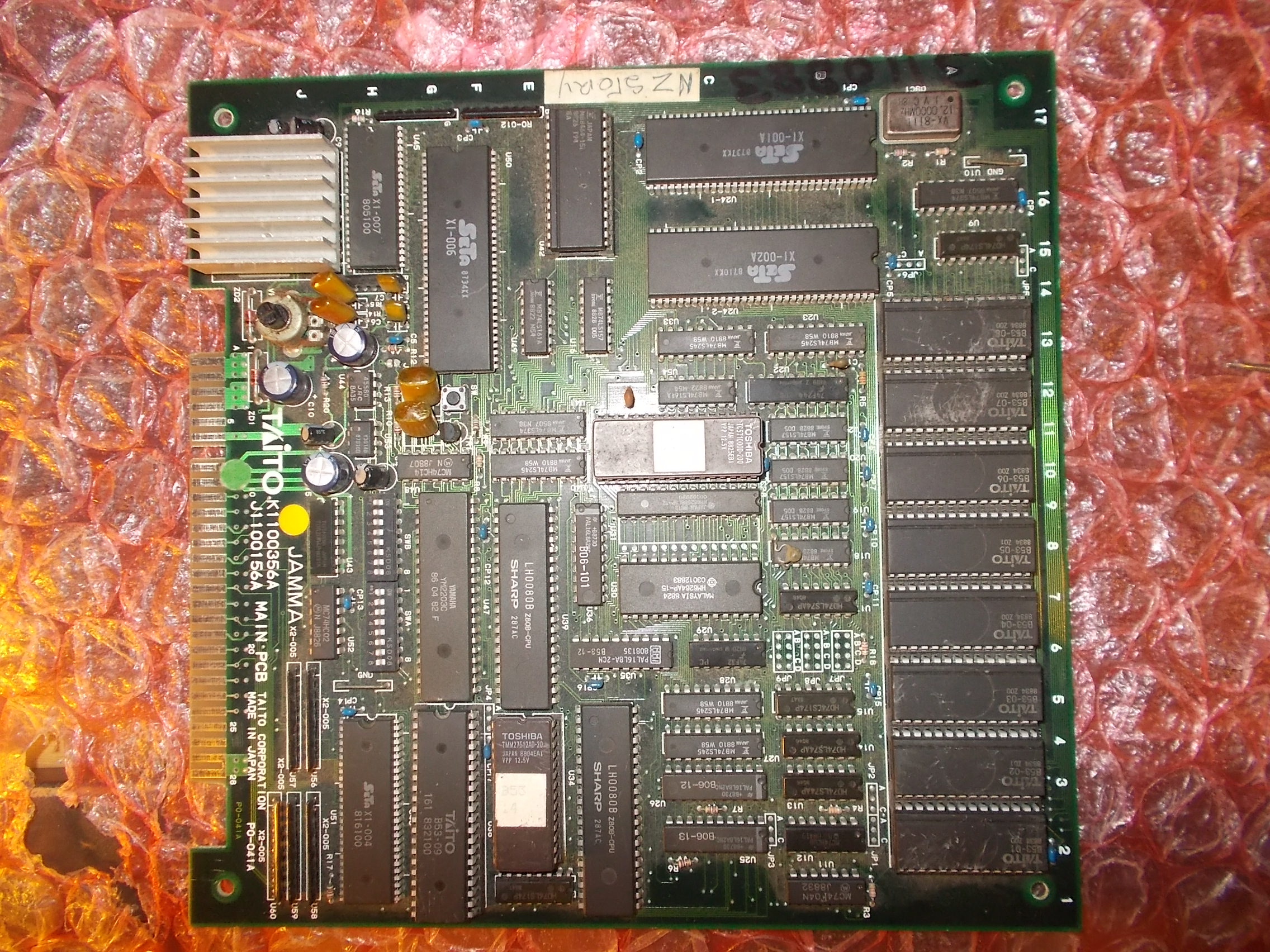
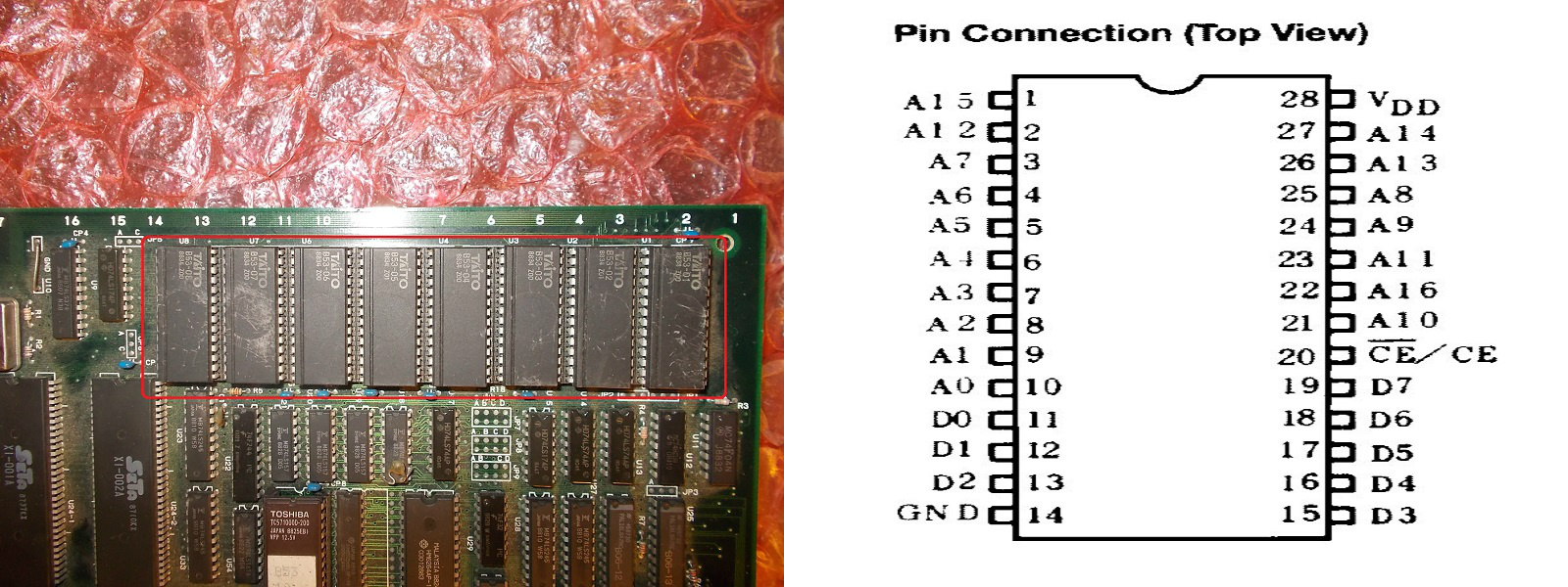
Received for repair from New Zealand this The New Zealand Story PCB (sorry for the wordplay…), the one layer hardware revision :
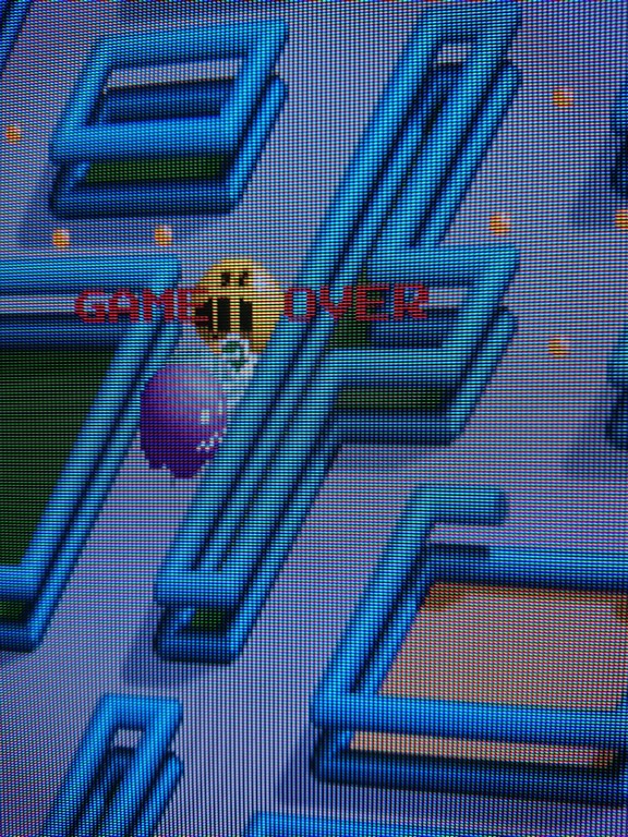
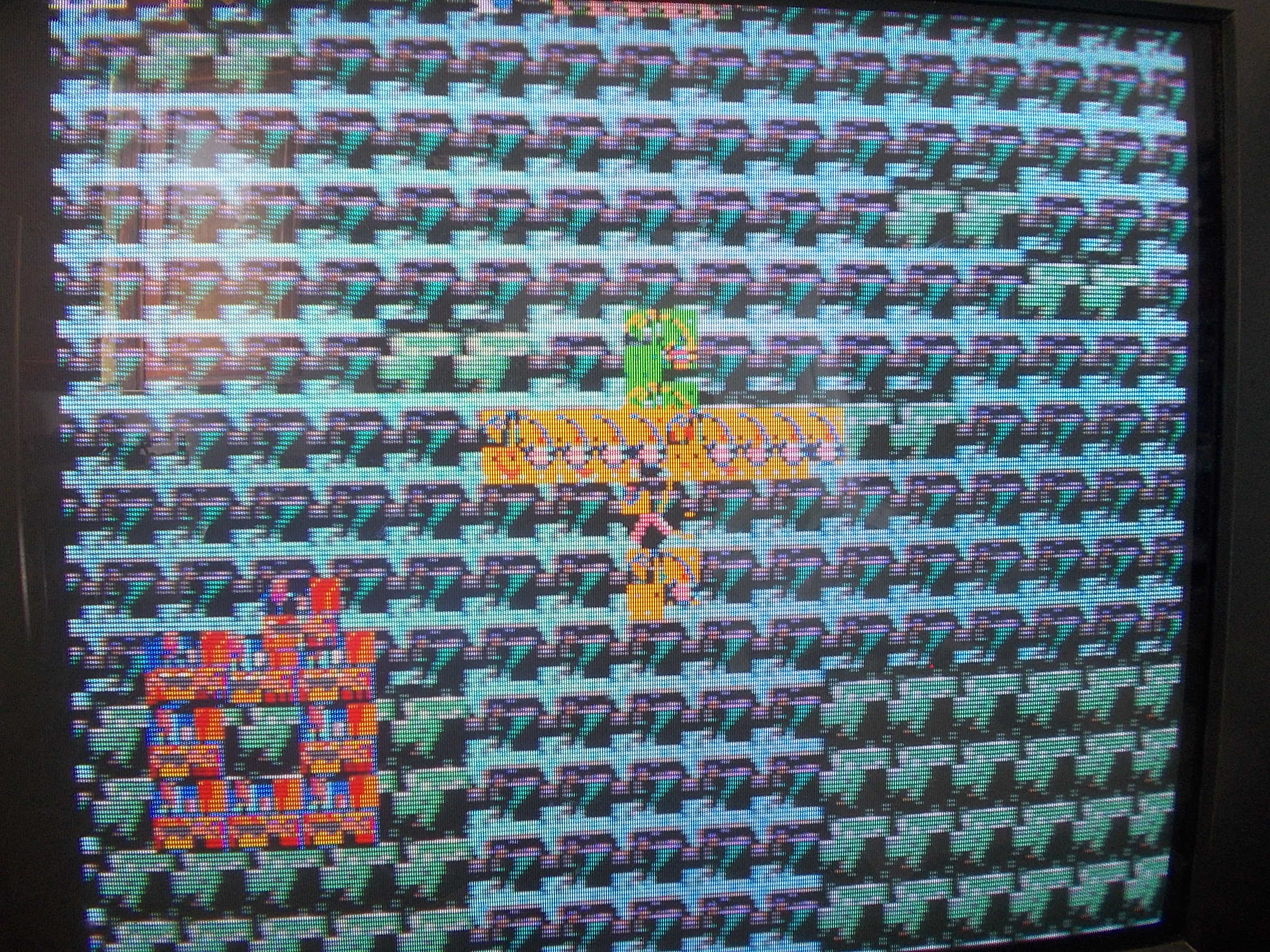
Board booted up but graphics were totally wrong :
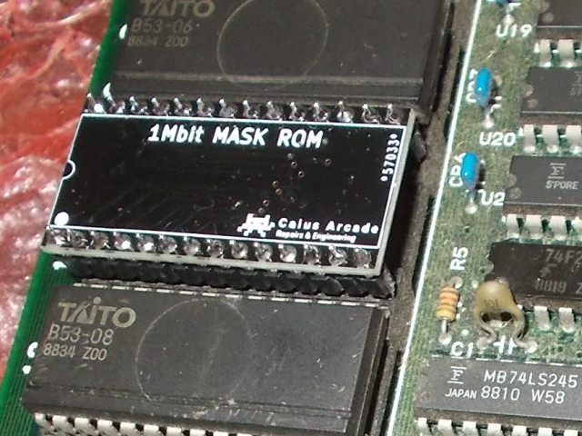
GFX data are stored in eight 28 pin 1Mbit MASK ROMs whose pinout is pretty identical to 32 pin 1Mbit non-JEDEC EPROM (extra pins apart)
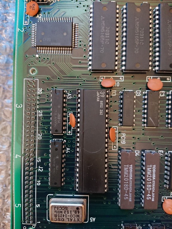
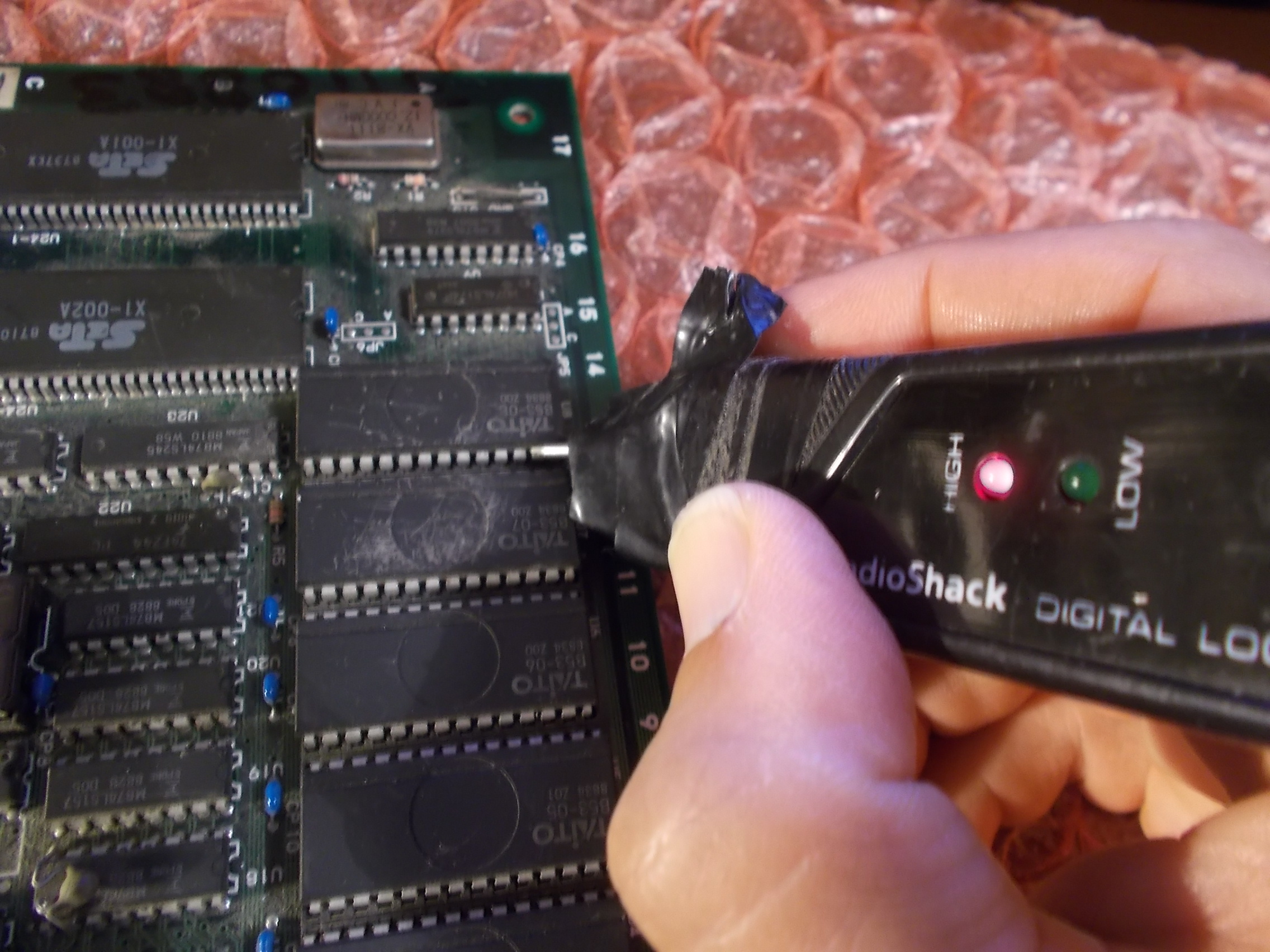
Before dumping them I used my logic probe and found stuck upper address lines (pin 12-13-14-15)
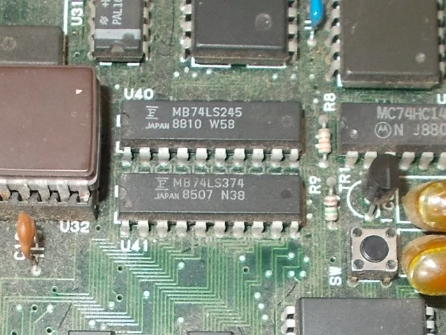
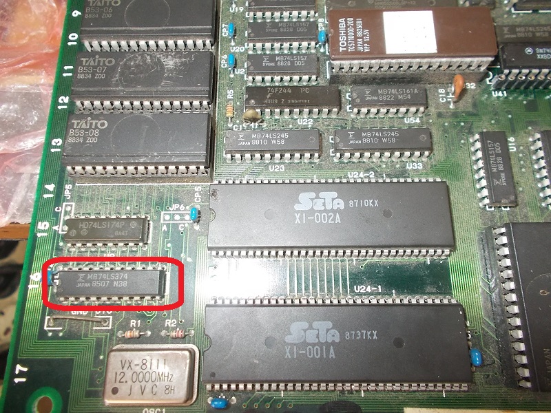
I traced the address lines back to outputs of a 74LS174 @U9 whose inputs were floating, these came from a Fujitsu 74LS374 @U41:
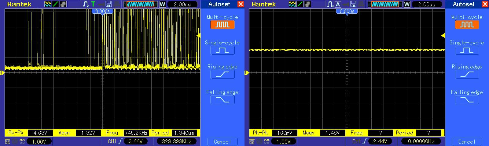
Inputs of it were toggling but all outputs were stuck at undefined voltage level of 1.48V, this is the typical way of failure of Fujitsu TTLs :
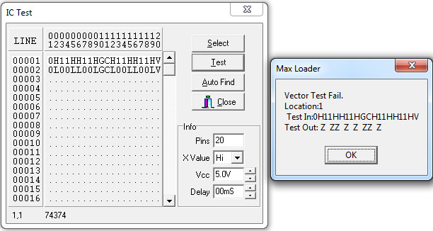
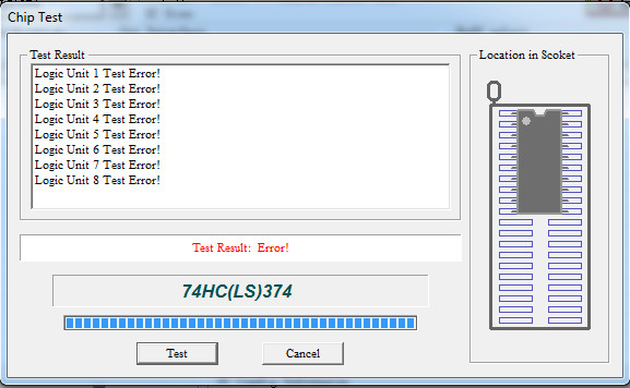
The chip failed the out-of-circuit testing, all outputs were indeed in ‘Z’ (or high-impedance if you prefer) state :
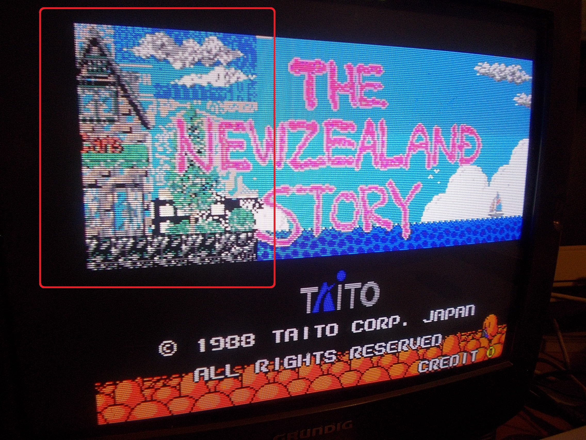
Once replaced the IC the graphics were restored but I noticed some corruption on title screen :
I dumped the 1Mbit MASK ROMs and my programmer complained about the one @U7 :
This was a good chance to use one of my adapters I designed some time ago for replacing the 28 pin 1Mbit MASK ROMs with a TSSOP Flash ROM
But suddenly during power cycling the graphics went bad again :
I quickly pinpointed the fault to another 74LS374 @U10 with floating outputs, another Fujitsu one obviously :
Chip totally failed the out-of-circuit testing:
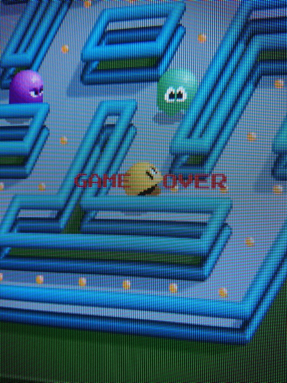
Graphics were now perfect so I started a game but controls didn’t work, the main character of both players moved by itself:
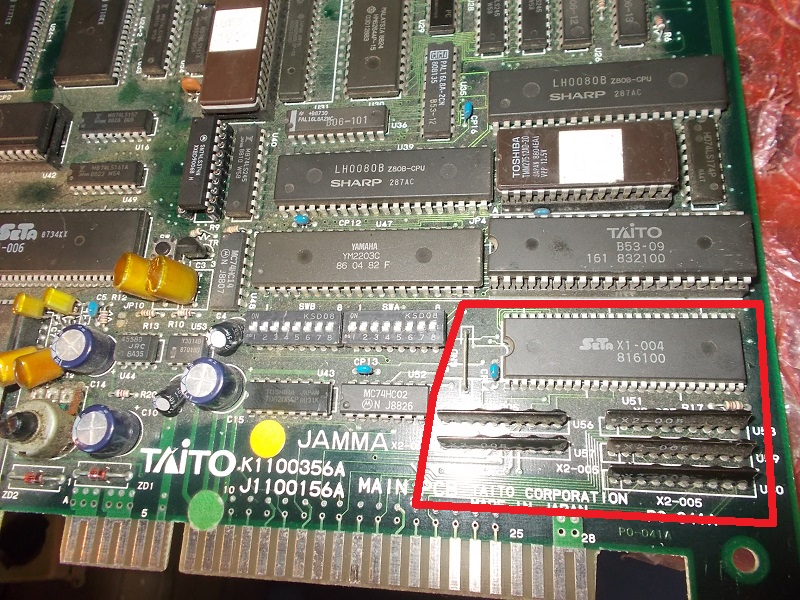
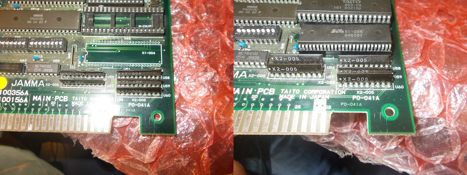
Looking at hardware I figured out the I/O circuit.The inputs from JAMMA connector go to some custom resistor arrays marked ‘X2-005’ and then signals are routed to a 52 pin SDIP custom chip marked ‘X1-004’ that handles them :
Resistor arrays did their job by pulling-up the signals and then routing them to the custom so most likely the ‘X1-004’ was bad.I played the card of replacing it but I had to struggle before finding a good spare as it seems this custom is quite prone to failure.I tried two donor parts but they were faulty until I caught the good one:
This fixed the controls and board completely.Repair accomplished.
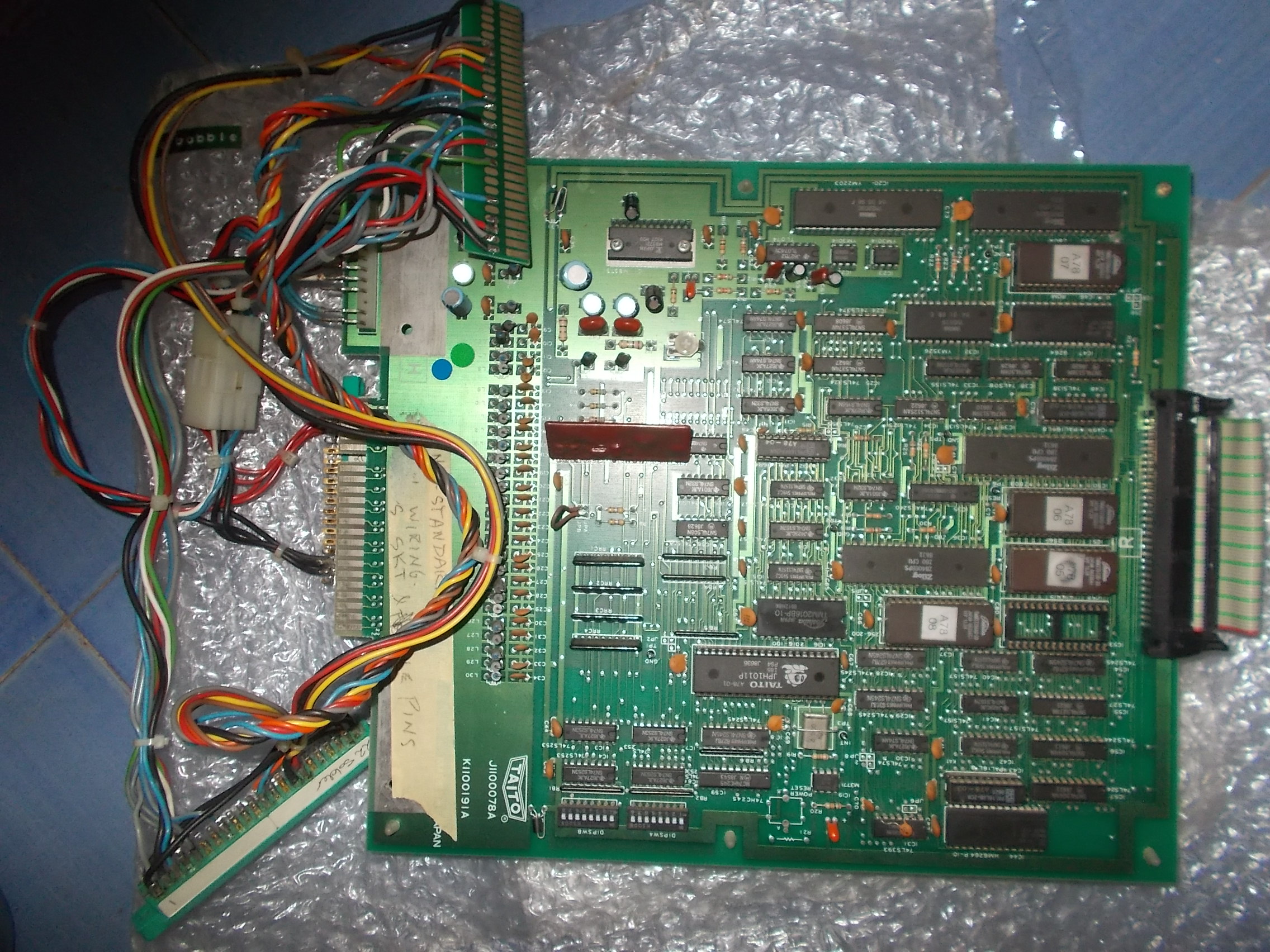
Received for repair from New Zealand an original Bubble Bobble PCB.Set is made of a CPU board
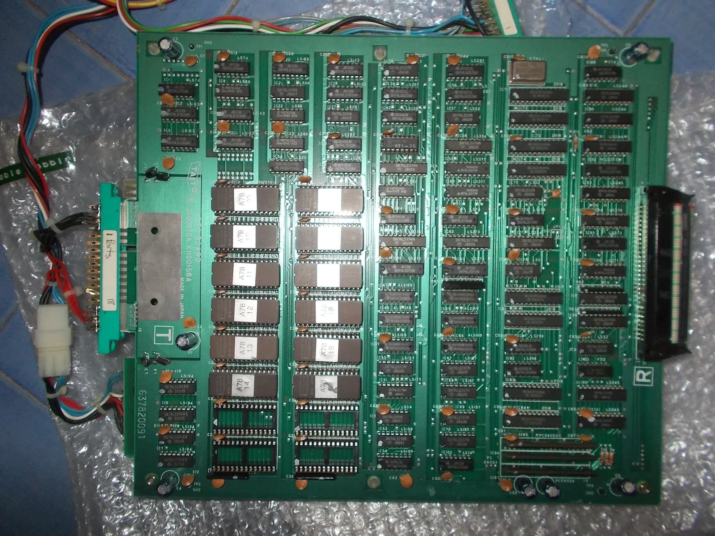
And a VIDEO board:
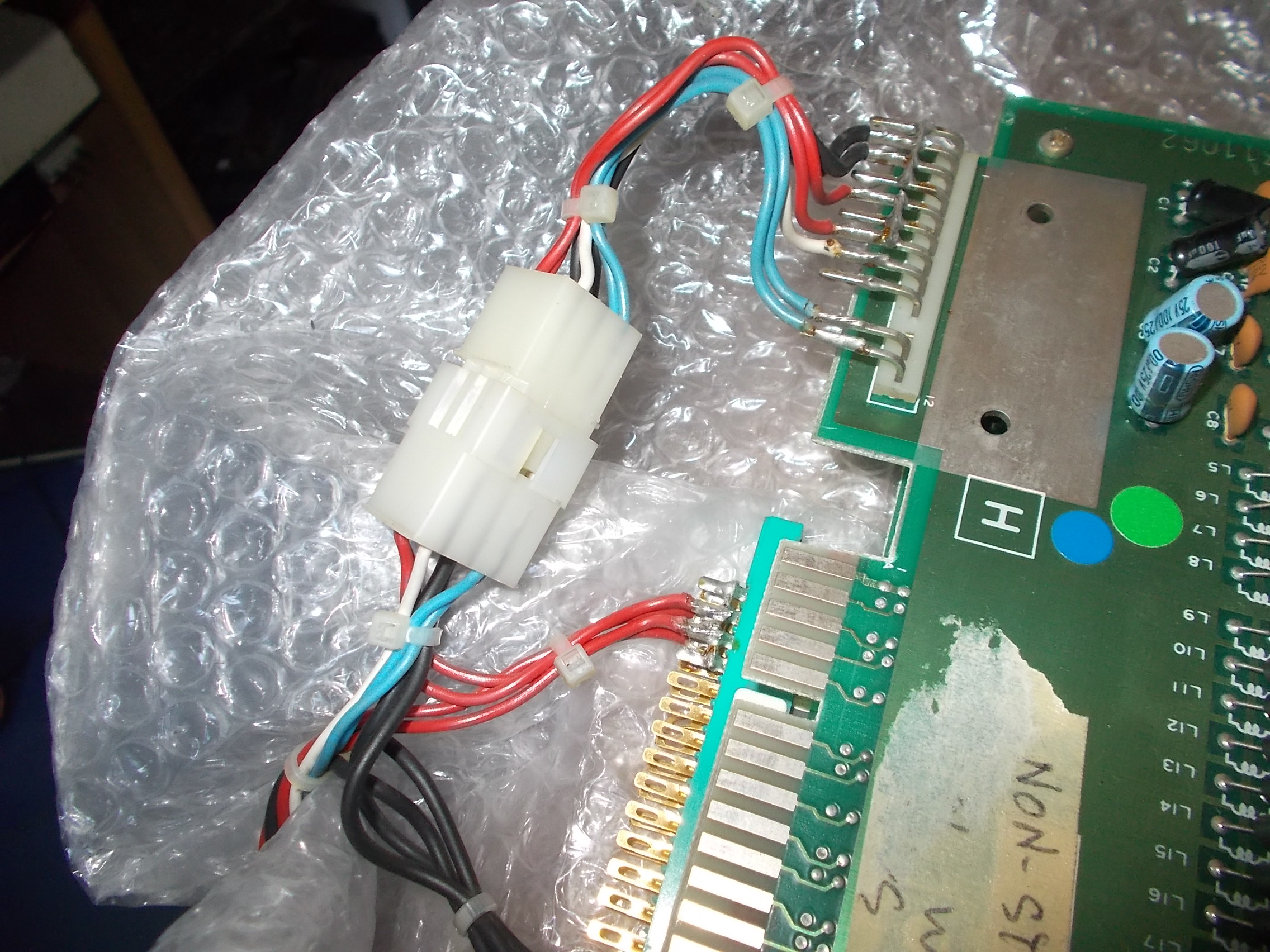
It came already adapted to JAMMA so it was just matter to plug it in.I did it but nothing came up on screen. I noticed wires were soldered onto the pins of ‘H’ connector and then a molex connector was used to carry power to JAMMA fingerboard:
I didn’t like this solution because it can cause loose connection so I removed the molex connector and soldered wires directly to JAMMA fingerboard.In this way the board properly booted up, games was perfectly playable with sound too but every alternate horizontal line of graphics was missing :
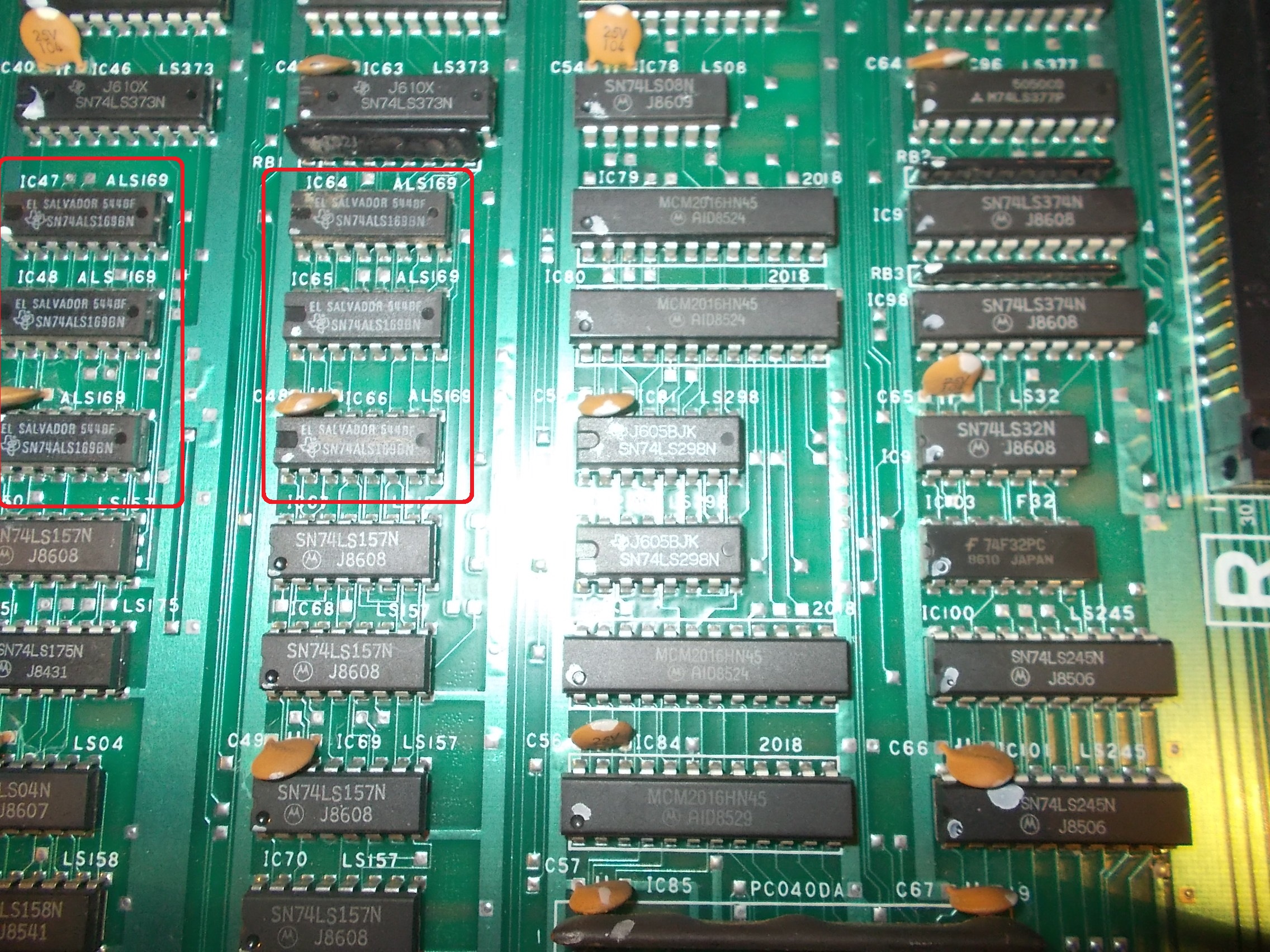
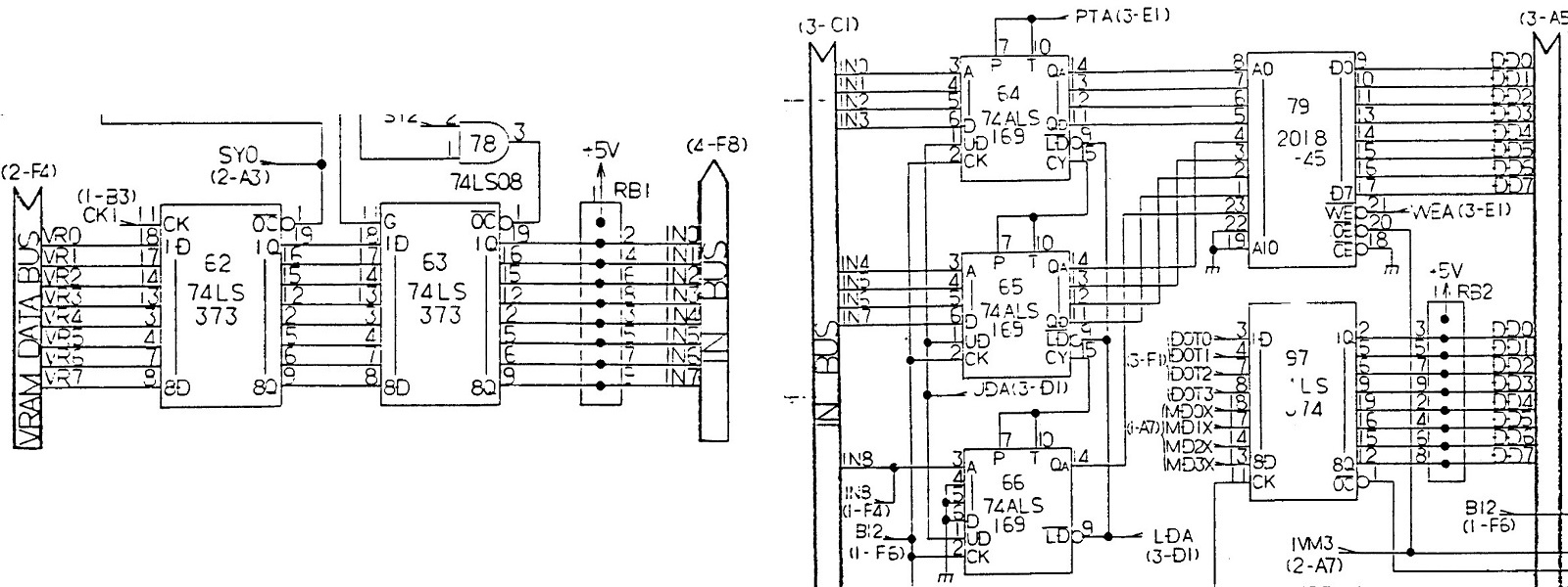
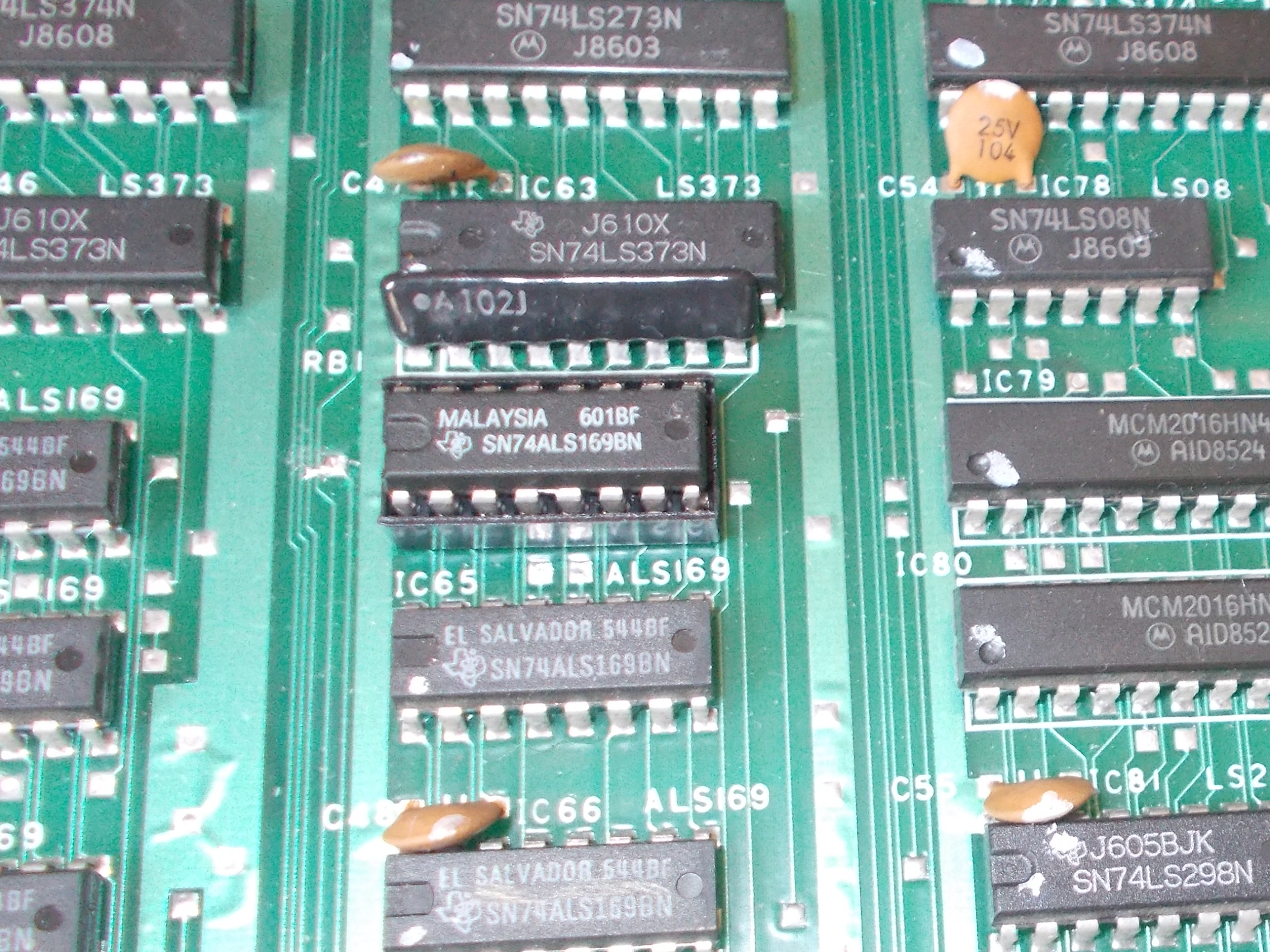
From top of my experience I know this kind of issue are most of times caused by bad counters (74LS161/163/169).Looking at board I spotted two rows of 74LS169 on bottom VIDEO board:
From schematics I could see they are involved in VIDEO RAM data bus, this made sense :
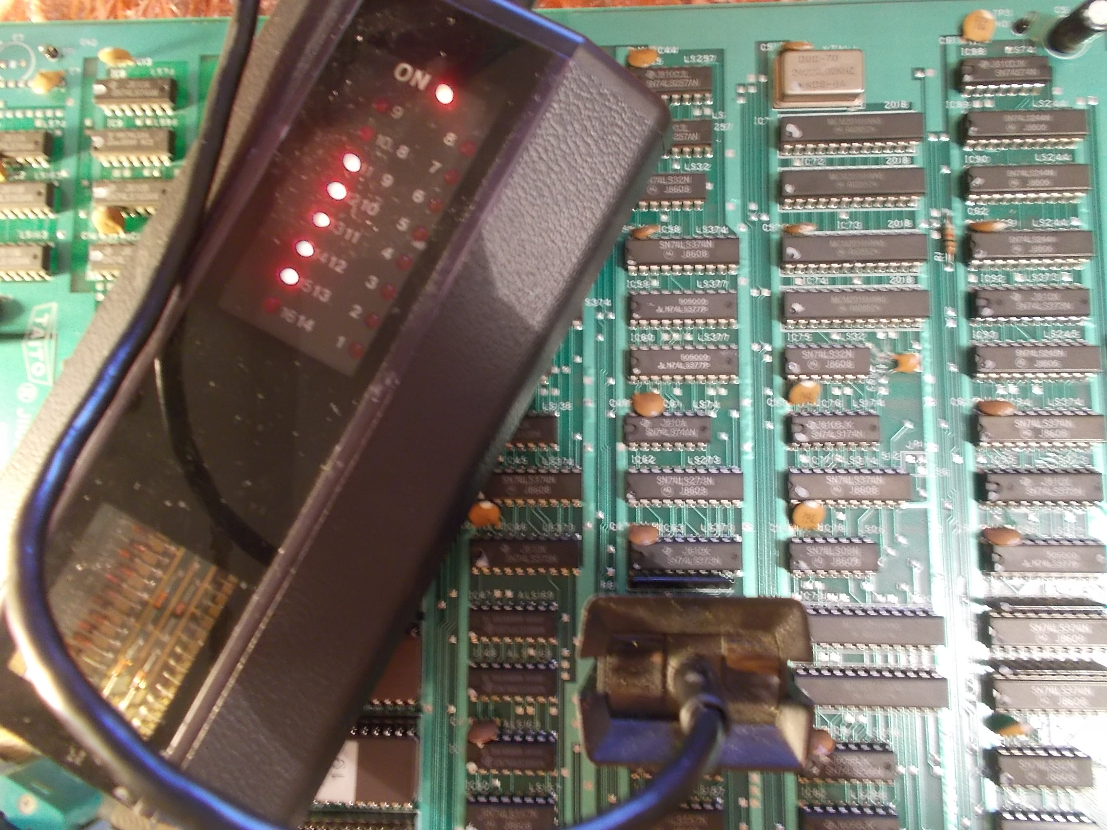
I went to probe these 74LS169 in circuit with my HP10529A logic comparator, all of them passed the test except the one @IC64 that gave troubles on all its outputs:
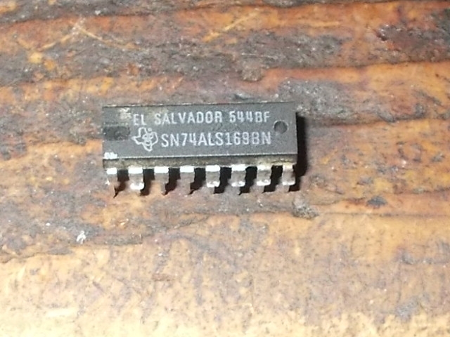
I pulled the part out :
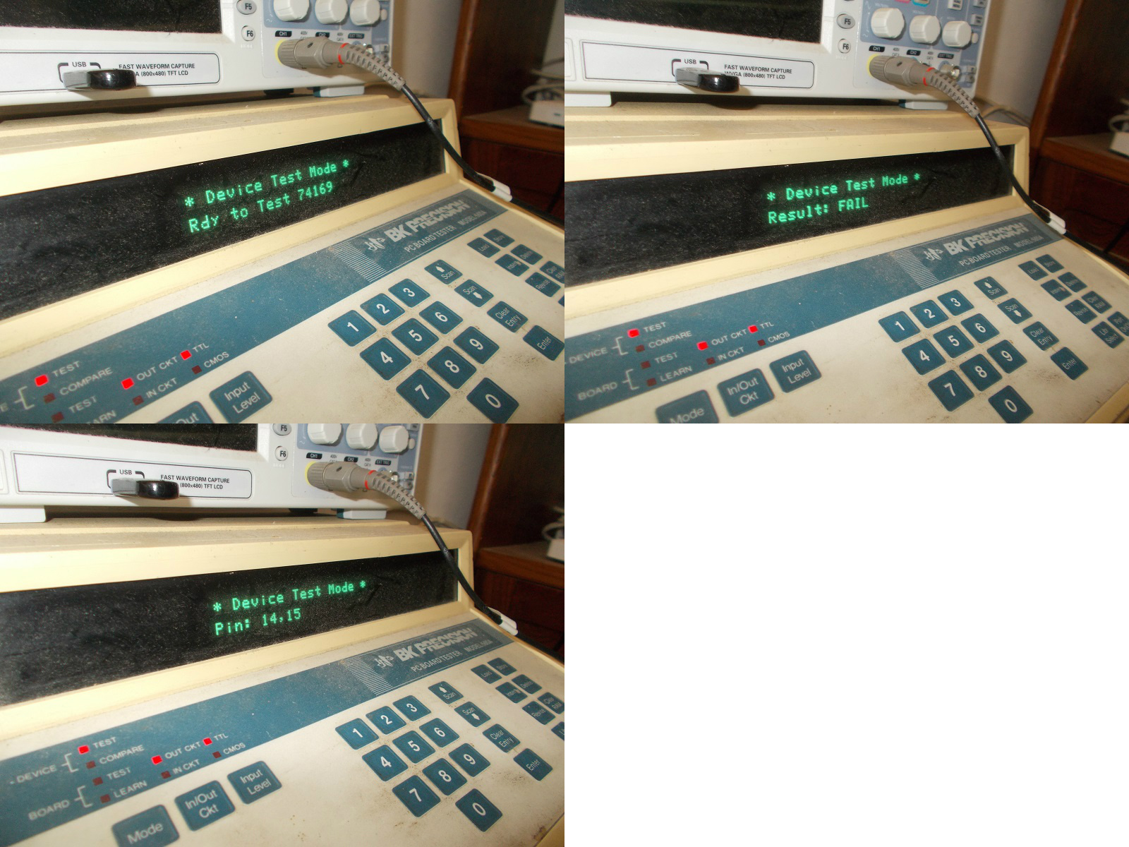
It failed the out-of-circuit test on my BK560 :
I installed socket and a fresh IC :
This cured the issue and fixed board completely.End of job.
PCB Repair LogsComments Off on Space Invaders DX double repair log
Jul262019
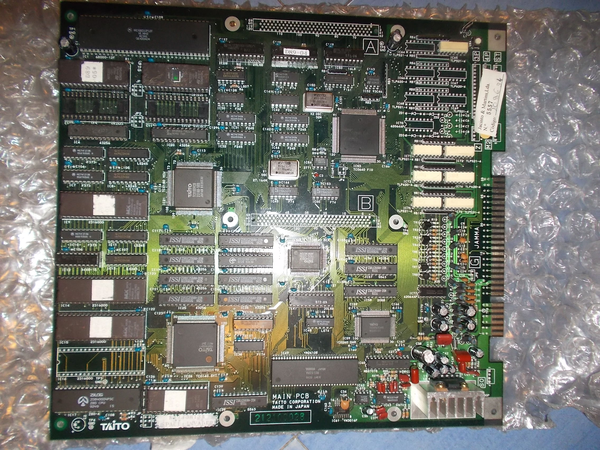
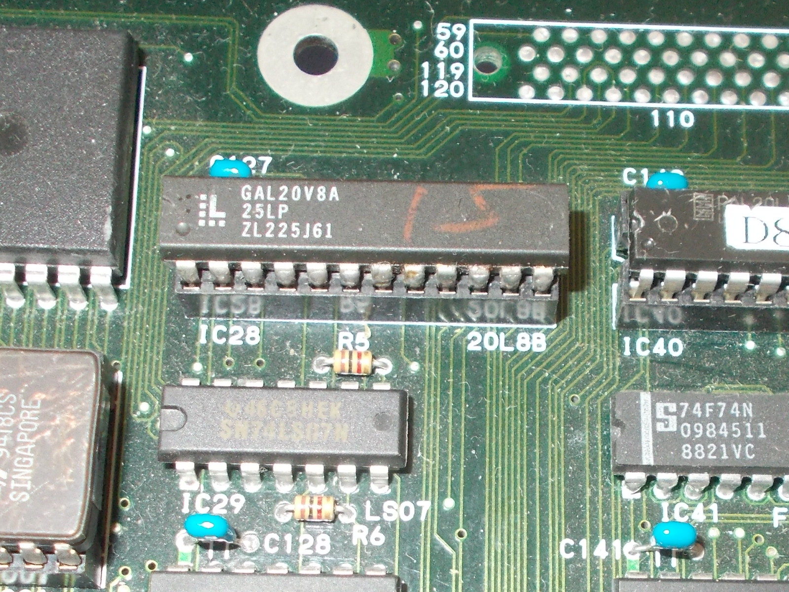
I received from Portugal a couple of Space Invades DX PCBs, a game released in 1994 by Taito (more or less a port of the original Space Invaders, with a few new features).
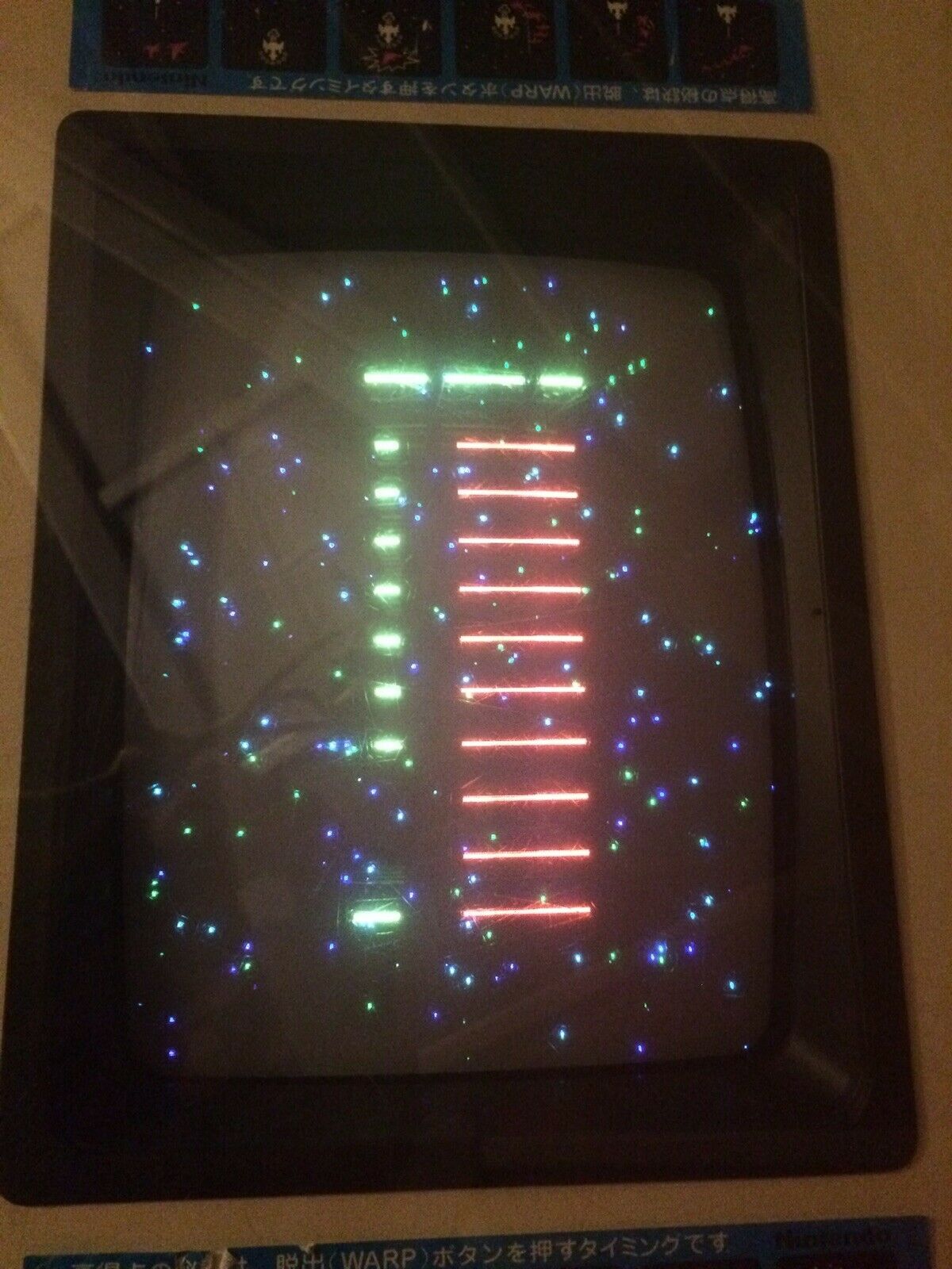
Both boards were in very good condition but completely dead.Here’s the first one:
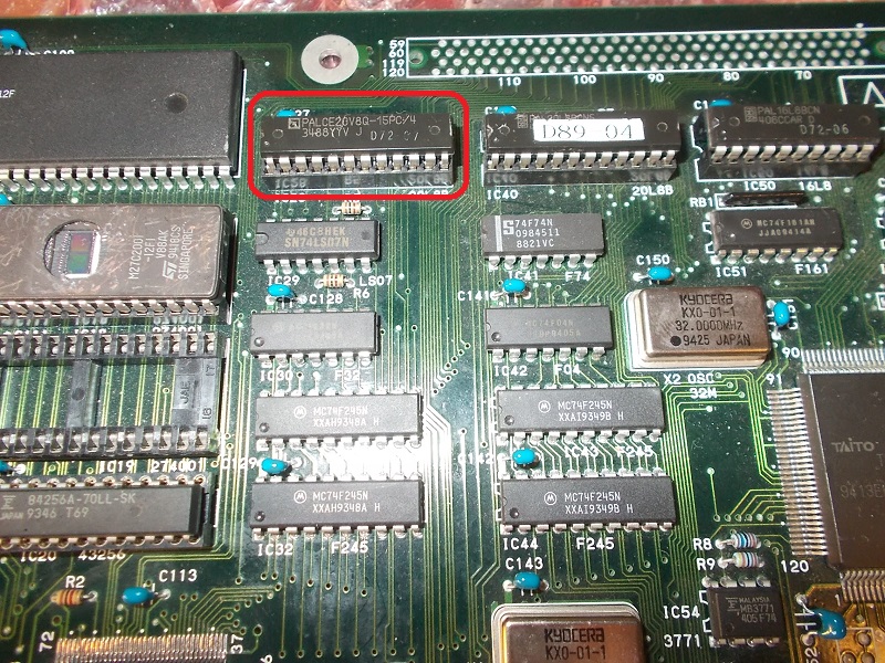
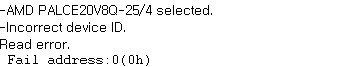
All I got on power up was a steady black screen.Probing the 68000 main CPU revealed the address/data busses were active but the three interrupts inputs (IPL0-IPL1-IPL2) were all in fixed high logical state.I traced these inputs back to a PALCE20V8 marked ‘D72-07’ :
Then I disassembled the fusemap of the MAME dump of this PAL being able to identify its inputs and outputs:
/** Outputs **/
Pin 15 = o15; /**(Combinatorial, No output feedback, Active low) **/
Pin 16 = o16; /**(Combinatorial, Output feedback output, Active low) **/
Pin 18 = o18; /**(Combinatorial, Output feedback output, Active low) **/
Pin 19 = o19; /**(Combinatorial, Output feedback output, Active low) **/
Pin 20 = o20; /**(Combinatorial, Output feedback output, Active low) **/
Pin 21 = o21; /**(Combinatorial, Output feedback output, Active low) **/
Pin 22 = o22; /**(Combinatorial, No output feedback, Active high) **/
Pin 20-21-22 were outputs to 68000 interrupts lines and they were confirmed to be stuck high along with all other outputs :
Although PAL was secured I tried to read it in my programmer, this would have at least told me the state of ‘health’ of the chip.Reading failed hence the chip was faulty:
I burned a GAL20V8 (GAL and PALCE are most of time interchangeable) with MAME fusemap :
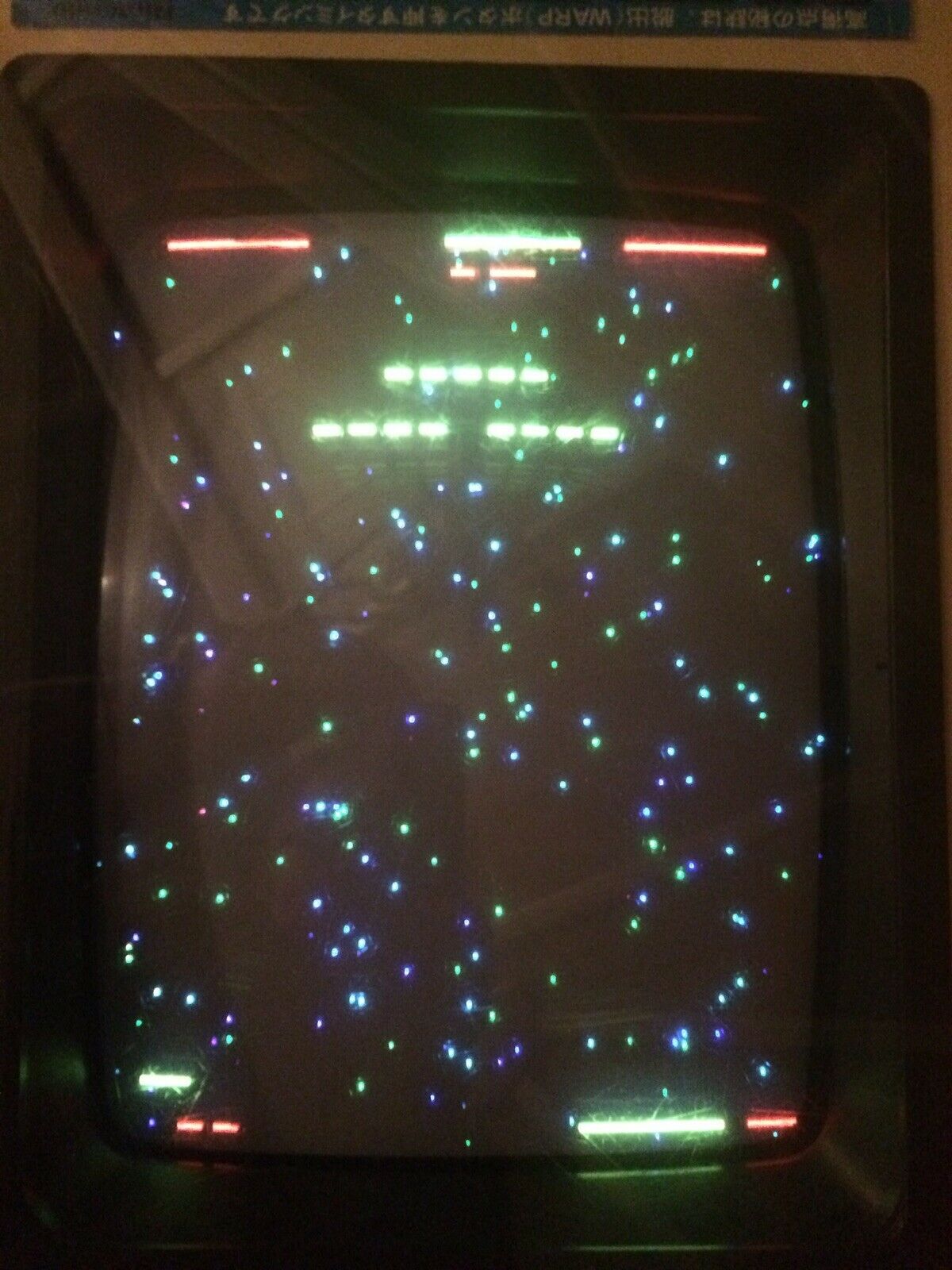
Board booted up with no further issue.First board repaired.
The second board:
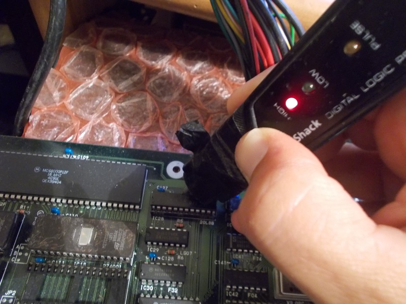
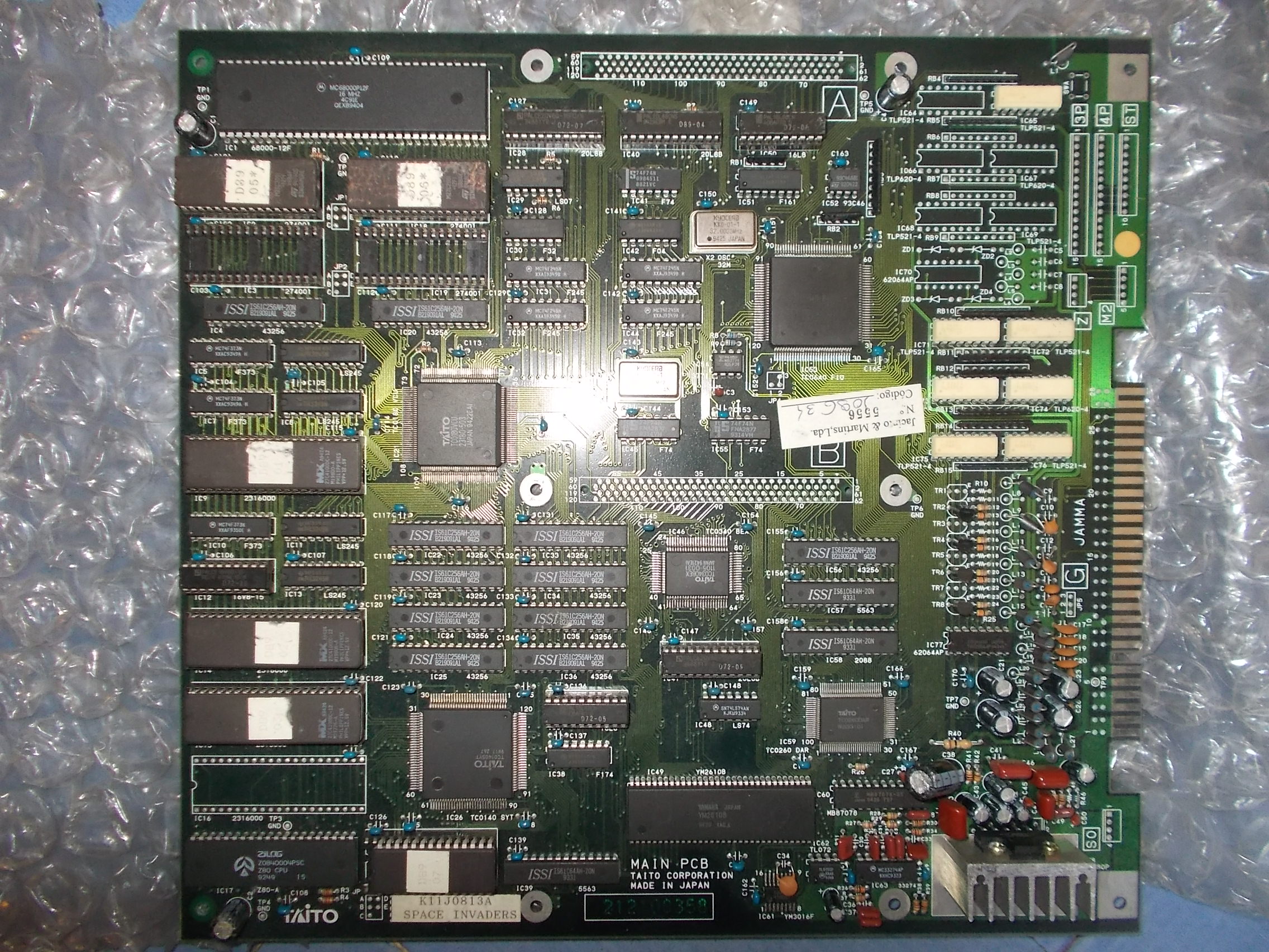
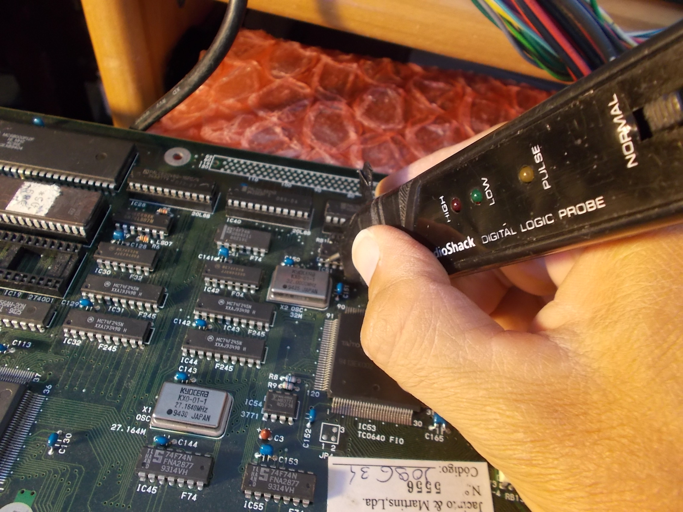
As said, it was completely dead.Probing the 68000 main CPU revealed the clock input was stuch high:
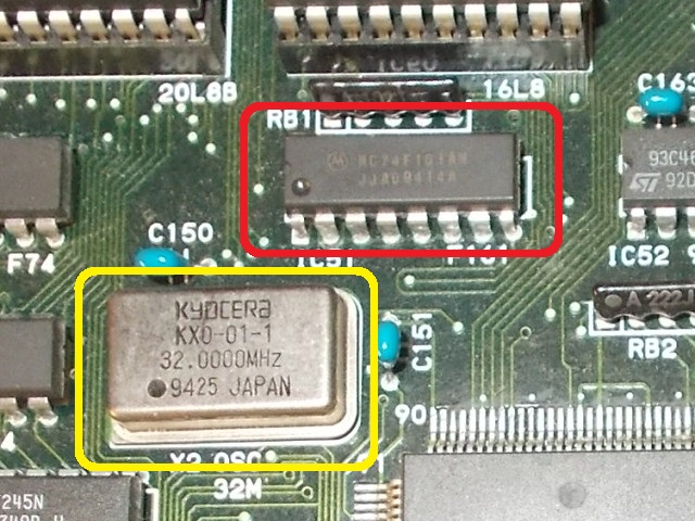
I traced it back to a 74F161 @IC51 which acts as a clock divider of the 32Mhz signal generated by the near oscillator :
There was nothing coming from the oscillator into the clock input (pin 2) of this 74F161 counter:
At first glance I thought the oscillator was dead but before replacing it I made a visual inspection on solder side.I found a dry joint on its output pin :
I promptly reflowed it and then powered up the board again.It booted up with no further issues.Double repair accomplished.
One drunken day at the excellent Revival event I offered to look at a Nintendo Space Firebird PCB.
Initially I was given the eBay link which had a few pictures of the fault.
When I got the board I did my usual visual checks and found a few things I didn’t like the look of.
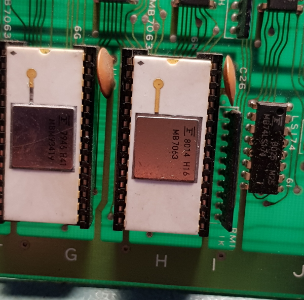
First up both main RAM chips are socketed. I removed these to check out of circuit and found this
I fixed that up by removing a leg from a donor chip and soldering it on
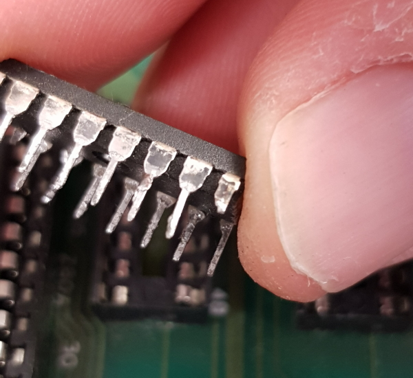
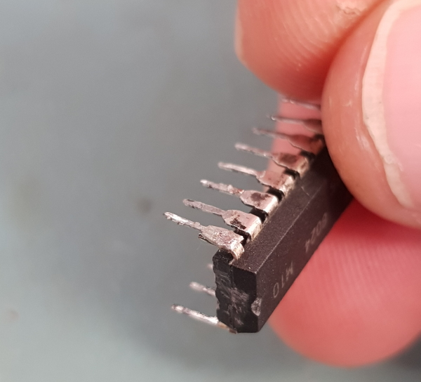
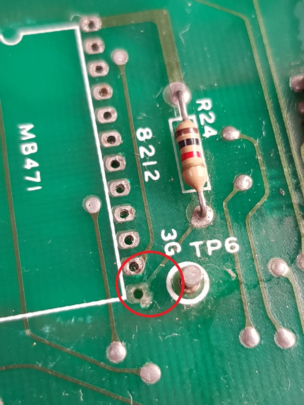
Next up was the 8212 Input/Output port. It too was socketed with a single wipe socket but what really got me suspicious was the state of the soldering
I wasn’t a fan of this so desoldered it. When I desoldered it I found this
A bit of trace has been lifted there. I can only assume this has been removed before.
I fitted a new socket and moved on.
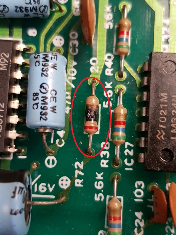
Found a burnt looking resistor on the sound PCB
The resistor still reads 20 ohms but i will replace that once my parts order comes in.
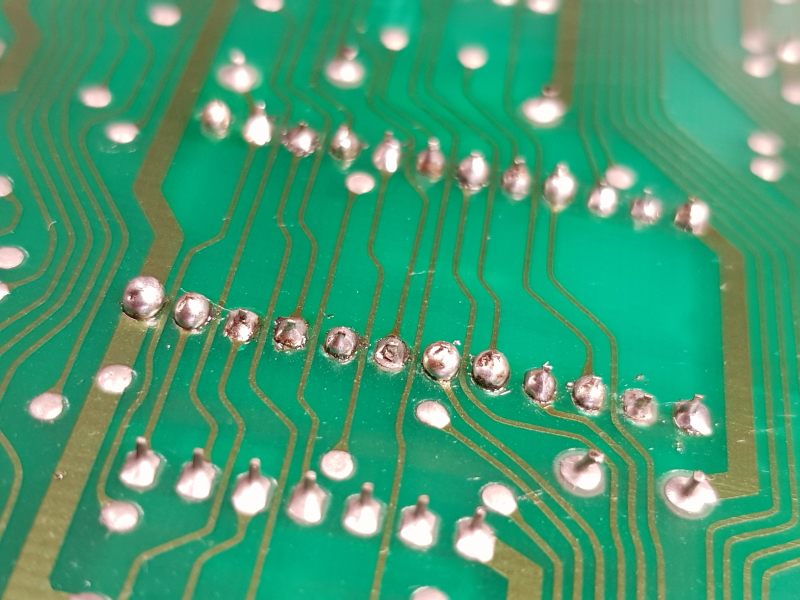
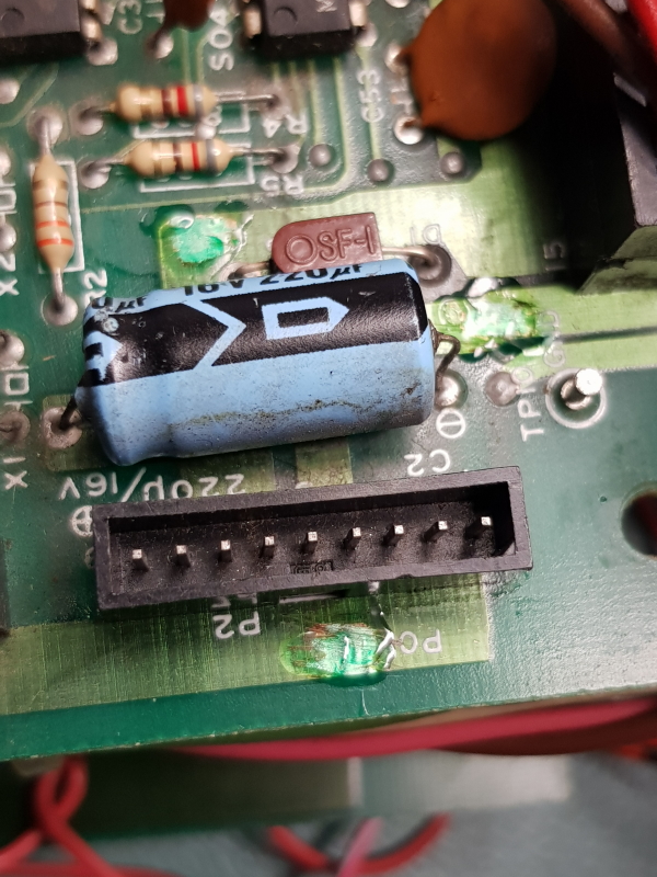
Lastly there were a few areas with the solder mask removed and solder on it. Not a huge problem but it needs addressed.
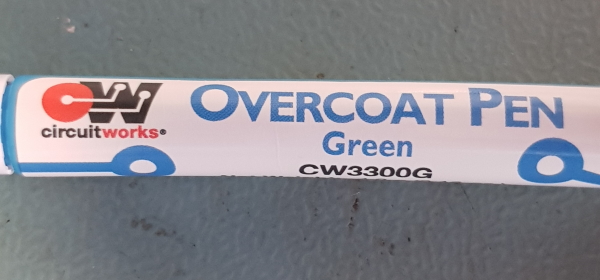
I cleared the excess solder from these places and covered them using a Chemtronics pen.
Not pretty but it does the job.
Firing up the PCB for the first time confirmed the original fault was still present.
As the fault was with the video I looked there first.
I started by reseating the two socketed RAM chips
To my surprise this fixed up the graphics. Not sure what effects the previous fixes would have had but Im not removing them to find out.
New problem now. The game hangs at the title screen at the same point every time.
Whenever I get issues like this I always think RAM or ROM issues.
I had already confirmed the RAM so went on to dealing with the ROM’s.
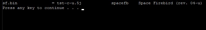
All of them were a match for Space Firebird according to MAME’s ROMident but the ROM at location 5J was for a different version of the game.
It should have been this
I erased and reprogrammed the 2716 EPROM and now the game plays fine.
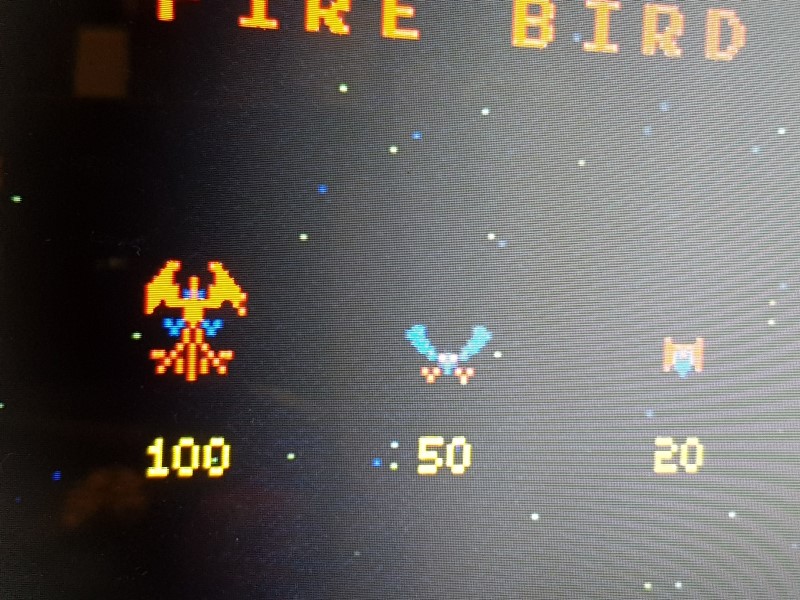
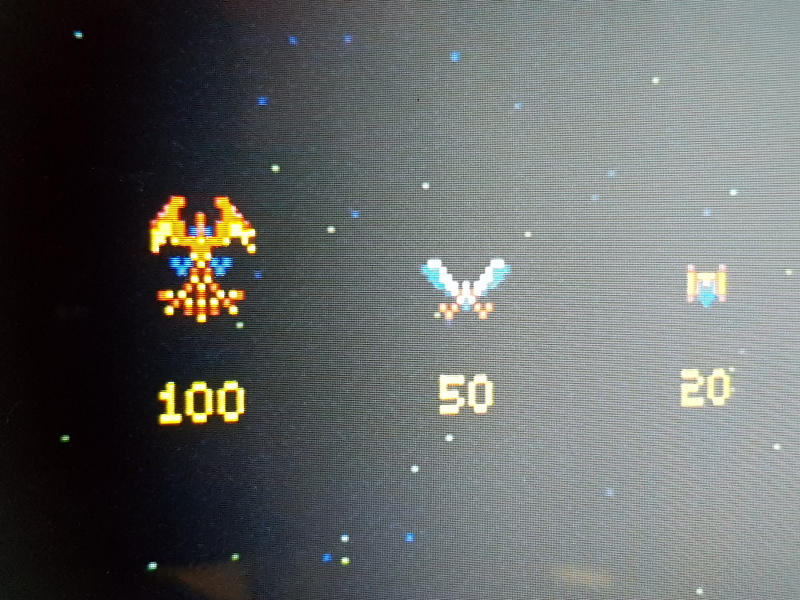
While comparing gameplay against MAME I realised some colours were missing
This should look more like this
I chased this round for quite a long time only to realise that the 74LS04 inverter I was using (as stated in the manual) to invert the colours was my problem. Switching to the proper Nintendo inverter PCB made everything look right again.
All that’s left now if to replace all those capacitors on the sound PCB and that burnt looking resistor and this board is done