Sep 212019
 

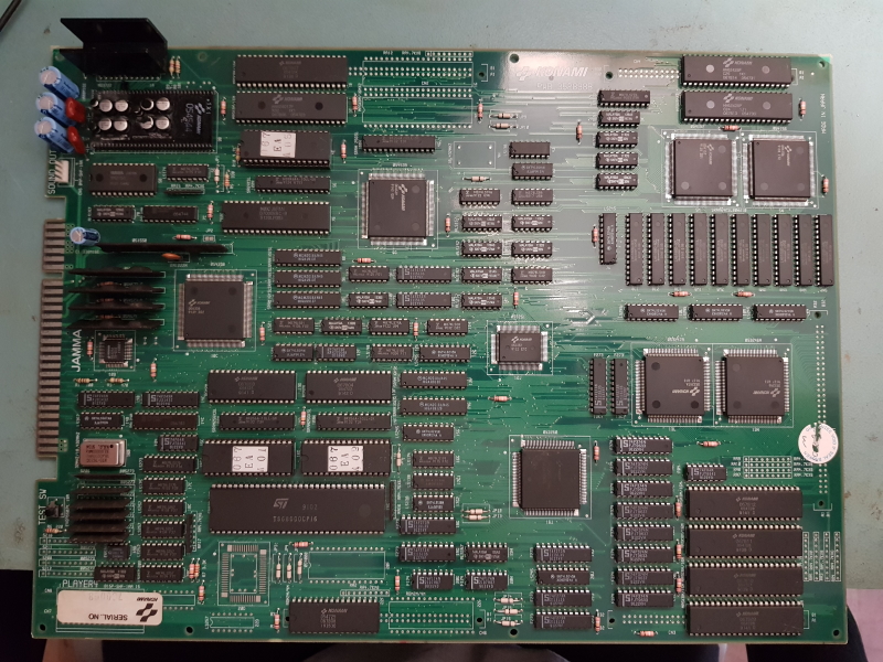
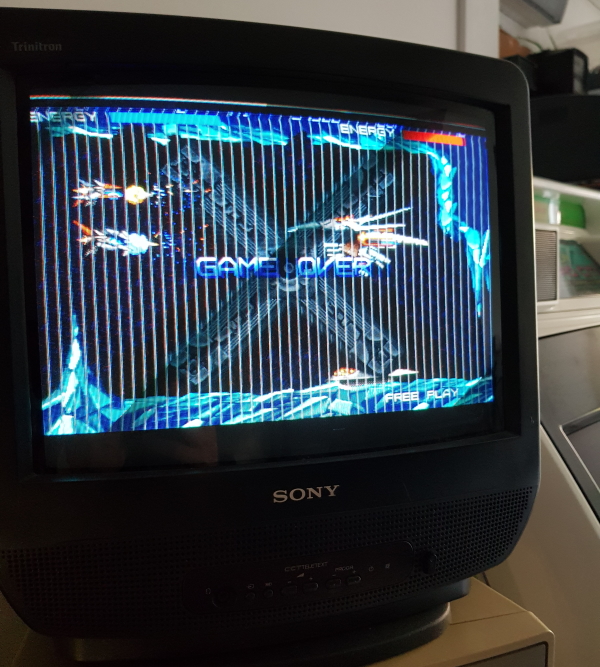
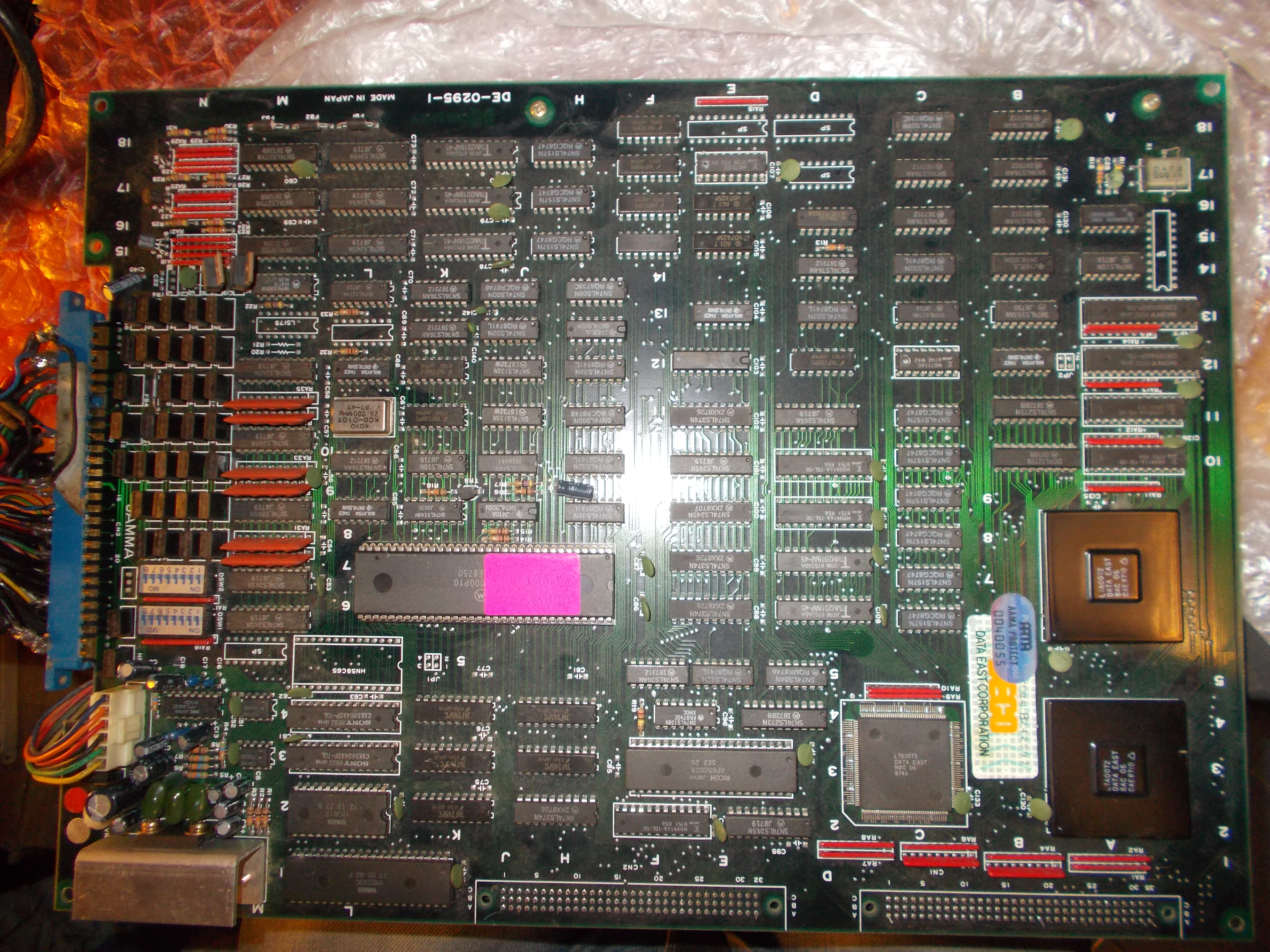
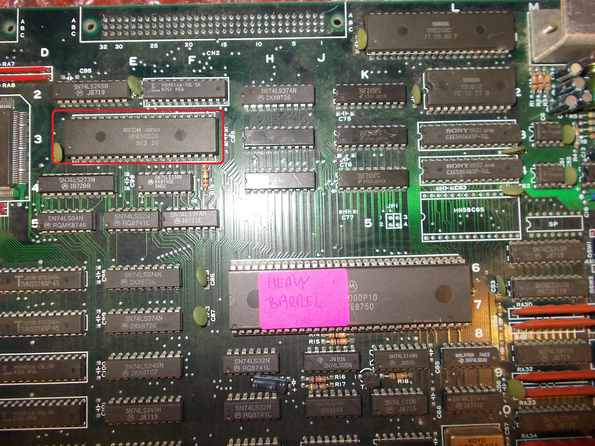
Received from Austria this Heavy Barrel PCB, a run and gun arcade game released by Data East in 1987 :

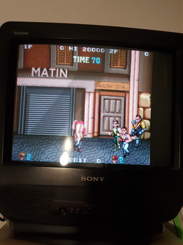
Board was in really good shape and game was fully playable too but lacked of sound :

Using an audio probe revealed no sound came out from analog circuit hence the fault was of digital nature.Audio system is ruled by a 6502 CPU located on top board :

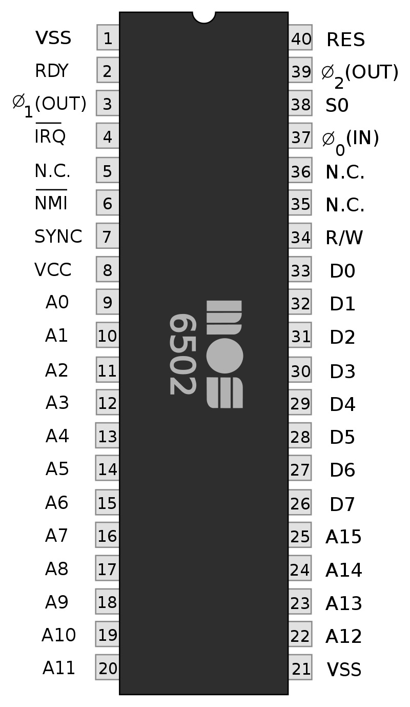
Its pinout :

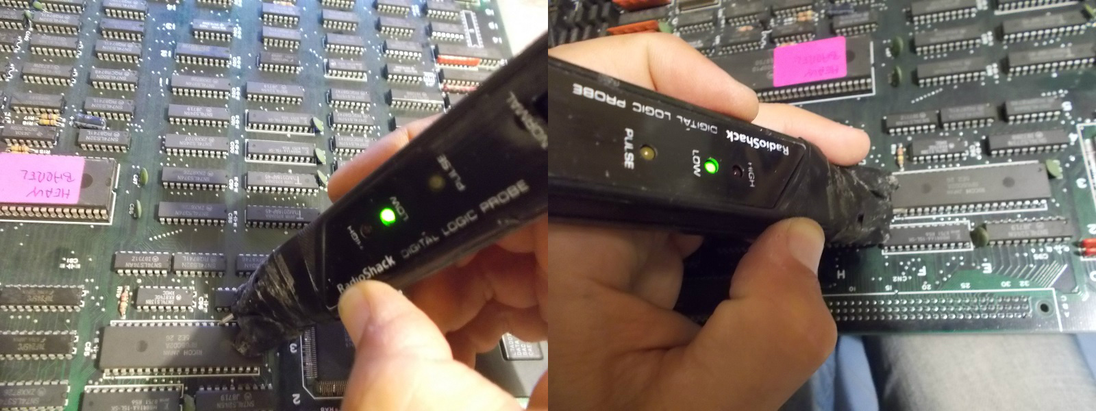
Checking it with a logic probe revealed that the /NMI line (pin 6) was asserted as well as two address lines were stuck low (A12 and A14)

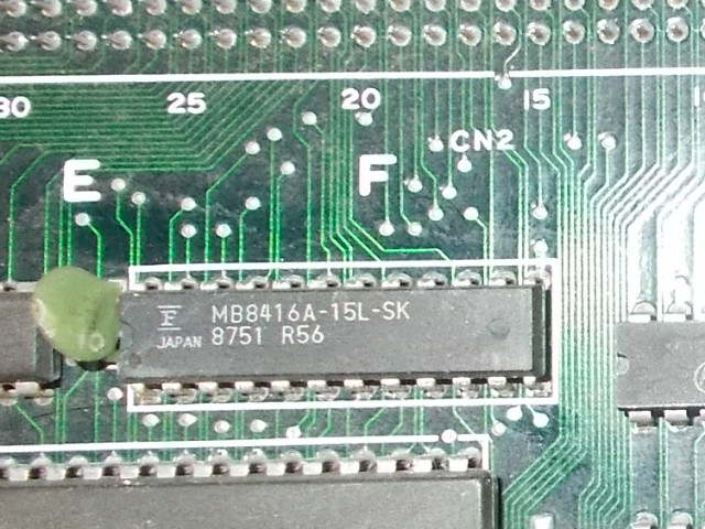
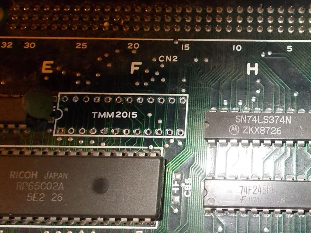
A non-maskable interrupt triggered is usually due to some hardware failure hence for first I dumped the ROM containing the audio code (located on bottom board), it turned out to be good.Then I focused on the RAM accessed by the 6502, a 8K x 8-bit device (6116 compatible)

As soon as I piggybacked it with a good chip I got some random sounds played.The scope revealed weak signals on some data lines of the RAM (a good signal on the left of below picture for comparison)

I removed the IC :

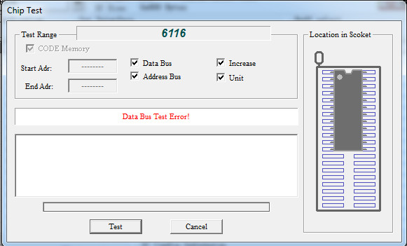
And sure enough, it failed the out-of-circuit testing :

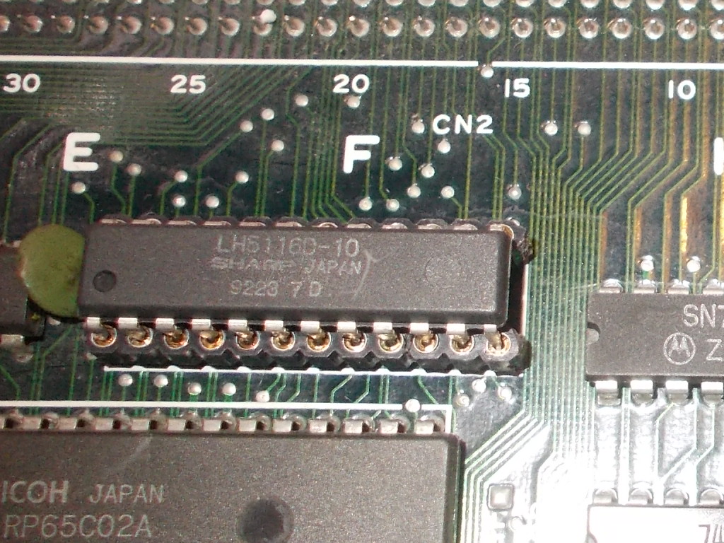
New chip fitted :

Sound was thus restored and another board fixed.

 Posted by at 10:31 pm

Muter BMR 2005 repair log

 Equipment Repair Logs, Repair Logs  Comments Off on Muter BMR 2005 repair log
Sep 142019
 

Not really much of a repair log but its just something I’ve been up to recently among other things.
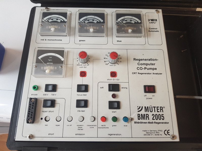
Saw this recently on eBay for a cheap cheap price.

I didn’t necessarily want the unit itself but more the CRT adapters it came with but the price was right.

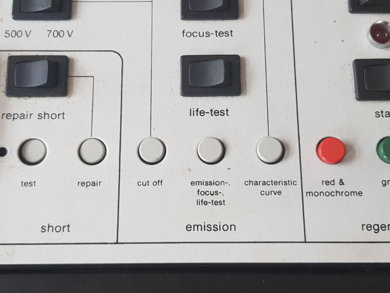
First pass on the visual inspection showed that something wasn’t quite right.

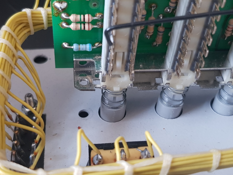
Removing the 4 screws on top lets you get into this thing and there is a spacer post and screw lying in the bottom which is clearly from the PCB housing all those buttons.

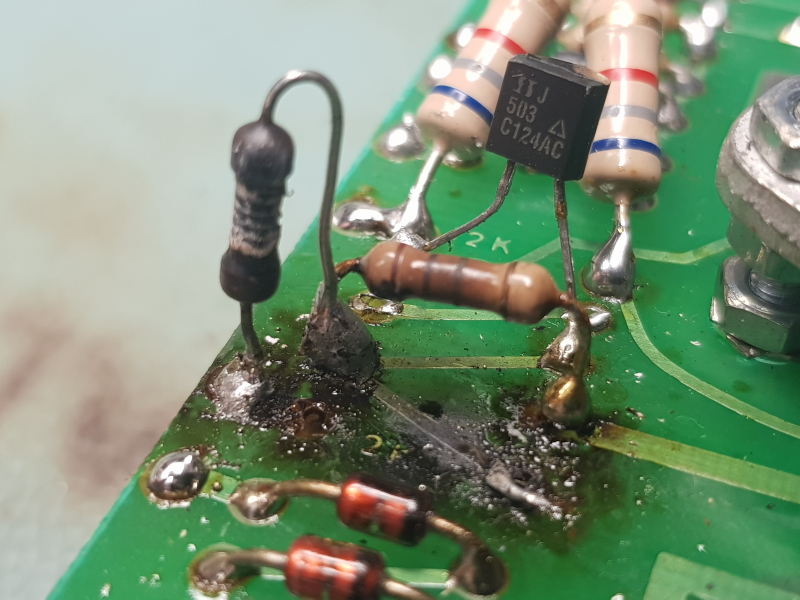
While fixing this in place I had a look over everything else and found something a little worrying.

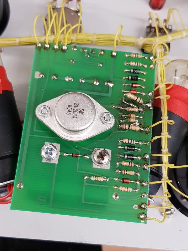
The crispiness aside this is not standard. There are 2 diodes missing and replaced with a transistor with the middle leg cut off, a lot of the traces are gone due to the charring and the 10K resistors have been replaced for two in series and are also the complete wrong value.
I just opted to remove all of this and replace with what it should be.

There is a schematic for this in the back of the manual so could check the values and the connections but I also have the BMR 95 which I took a look at as well

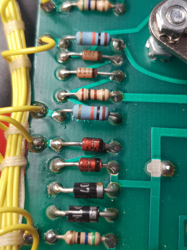
Here is what I ended up with

Its by no means a neat job but short of reproducing that little PCB its pretty much the best I could do given the amount of damage.
I checked all the other components on this and they tested good.
I have now tested this on one of my monitors and compared the readings against my other unit and they are all good so Ill consider this one fixed.

 Posted by at 3:57 pm

Rapid Hero repair log

 PCB Repair Logs  Comments Off on Rapid Hero repair log
Aug 292019
 

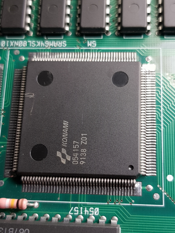
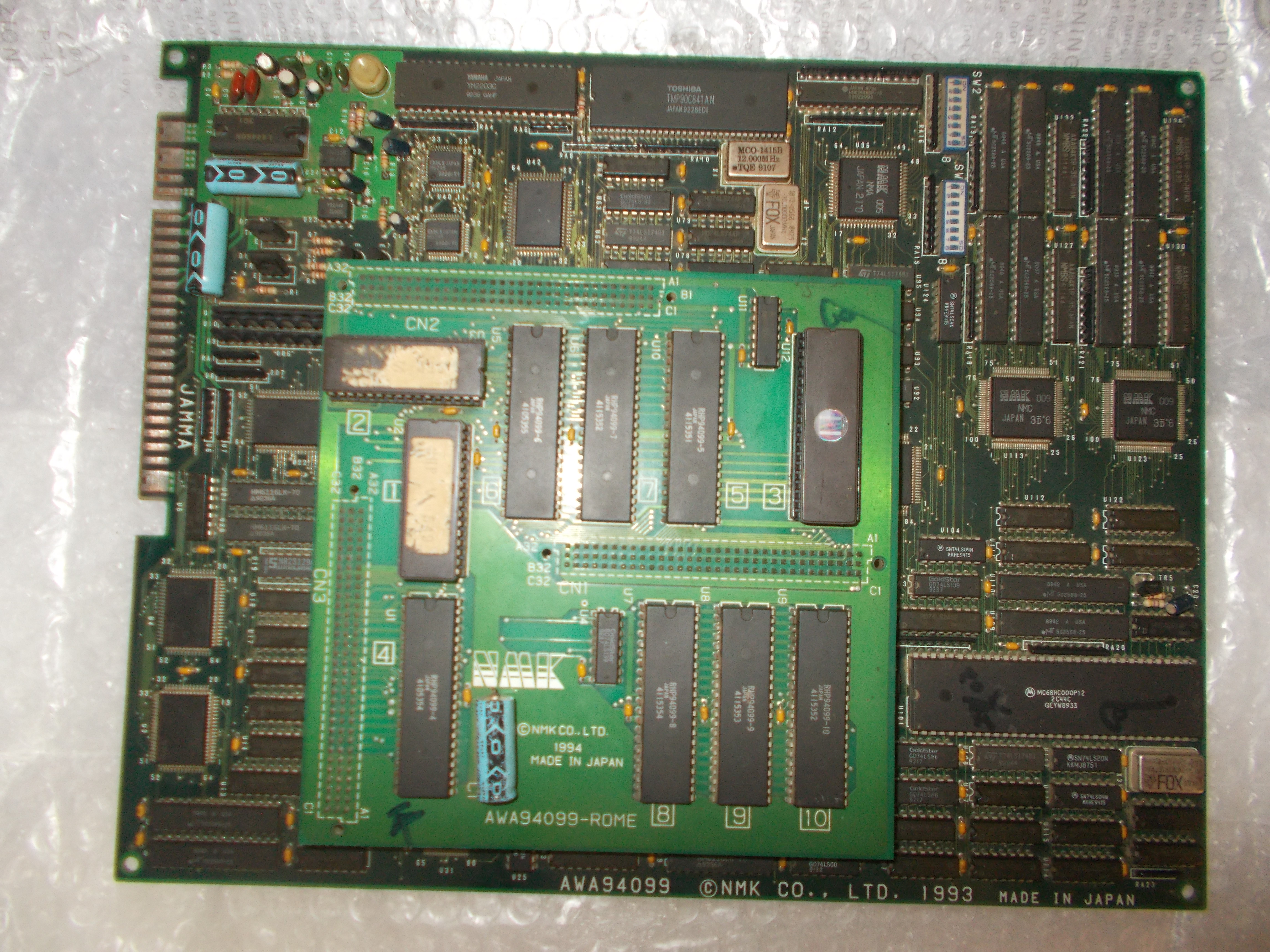
Got for repair this original Rapid Hero PCB, an obscure vertical shoot ’em up released by NMK in 1994 and a very sought-after board :

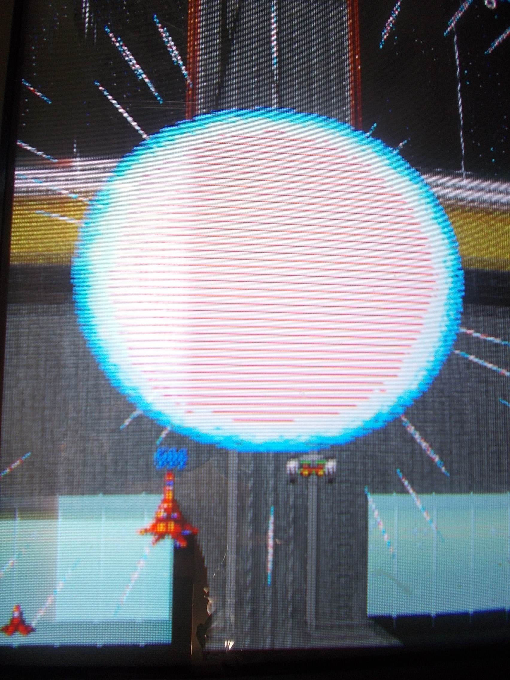
The board booted up but some sprites were affected by jailbars :

Besides, an entire music track was missing or sometimes corrupted as well as some sound effects:


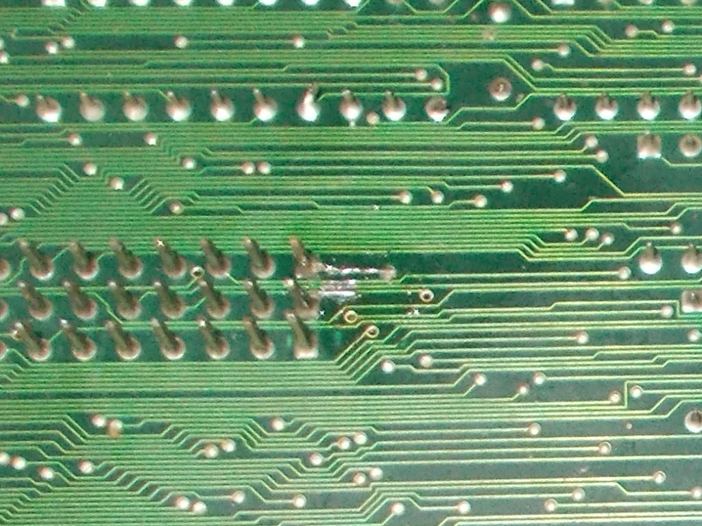
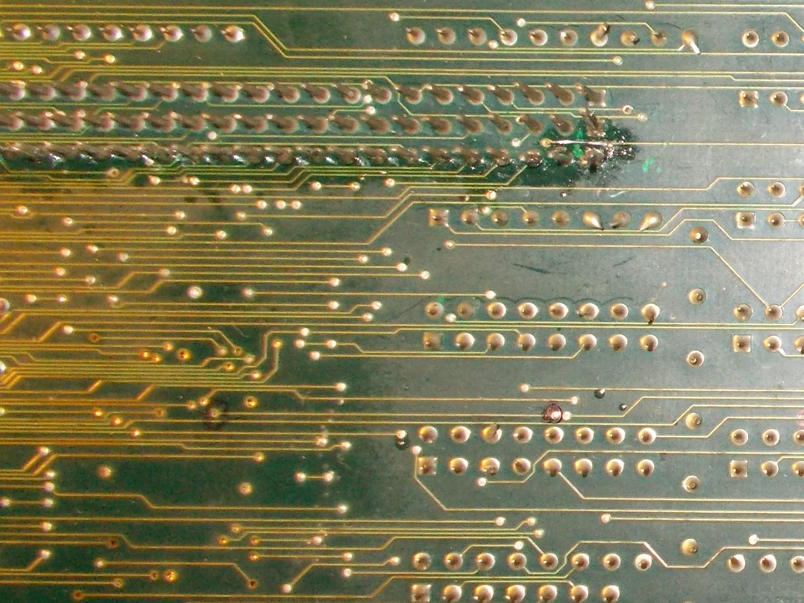
The board had some sign of previous repair on solder side :

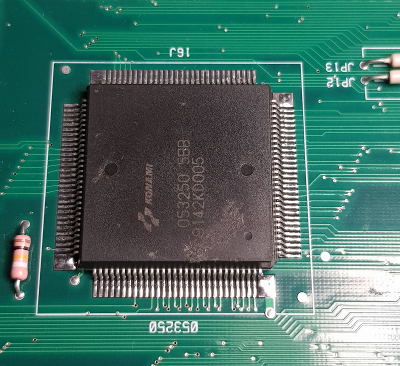
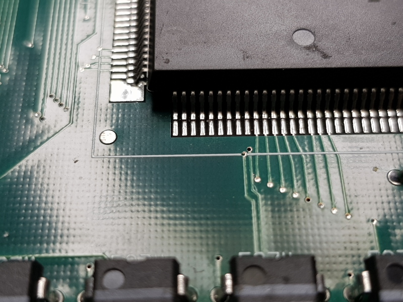
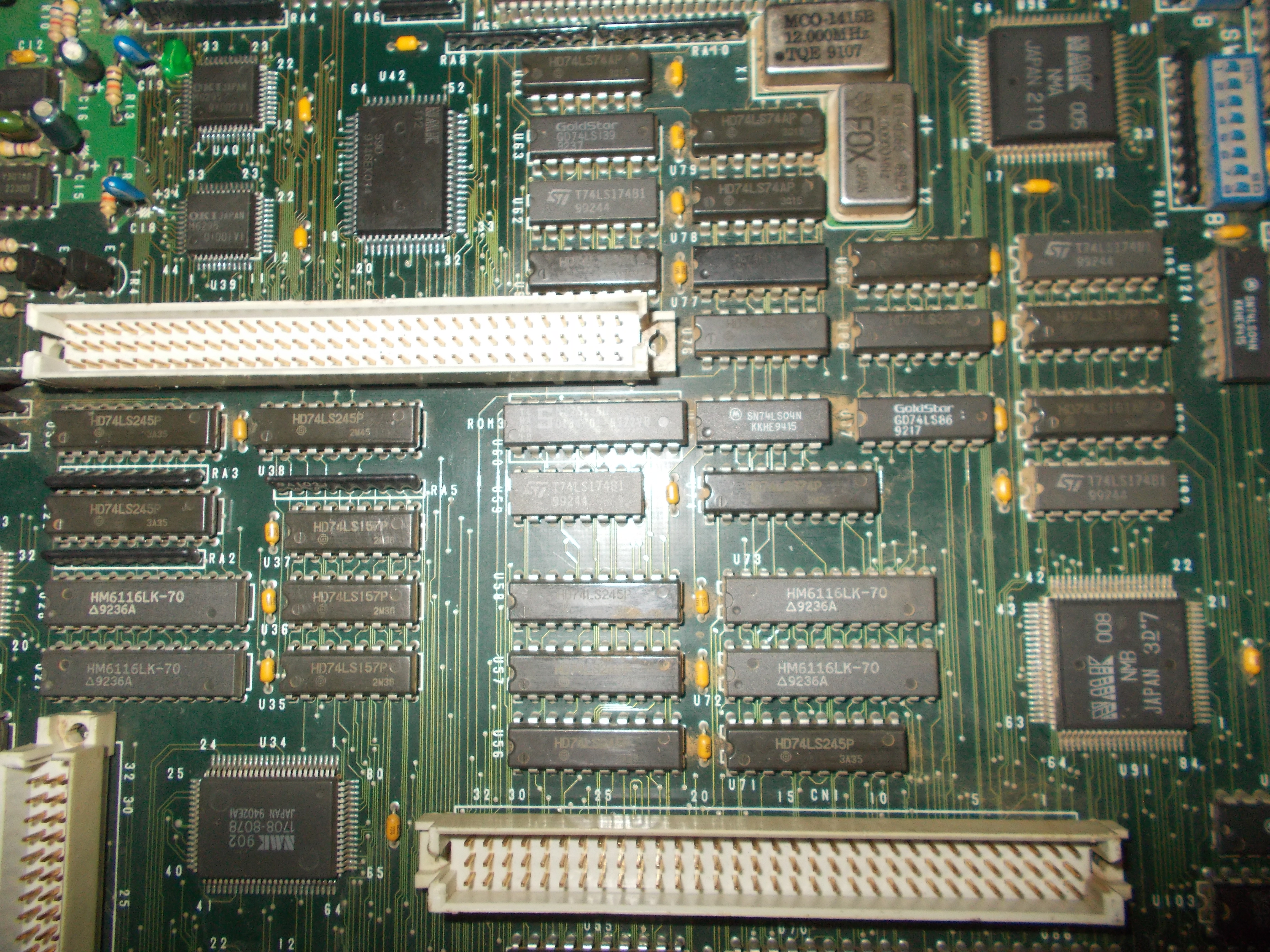
This is the area of the ‘CN1’ and ‘CN2’ connectors where the ROM board, which contains all the game code and data, plugs into the mainboard:

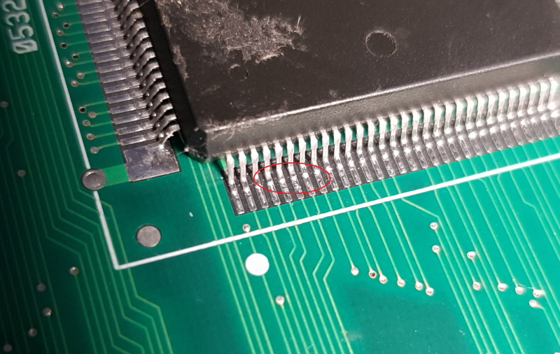
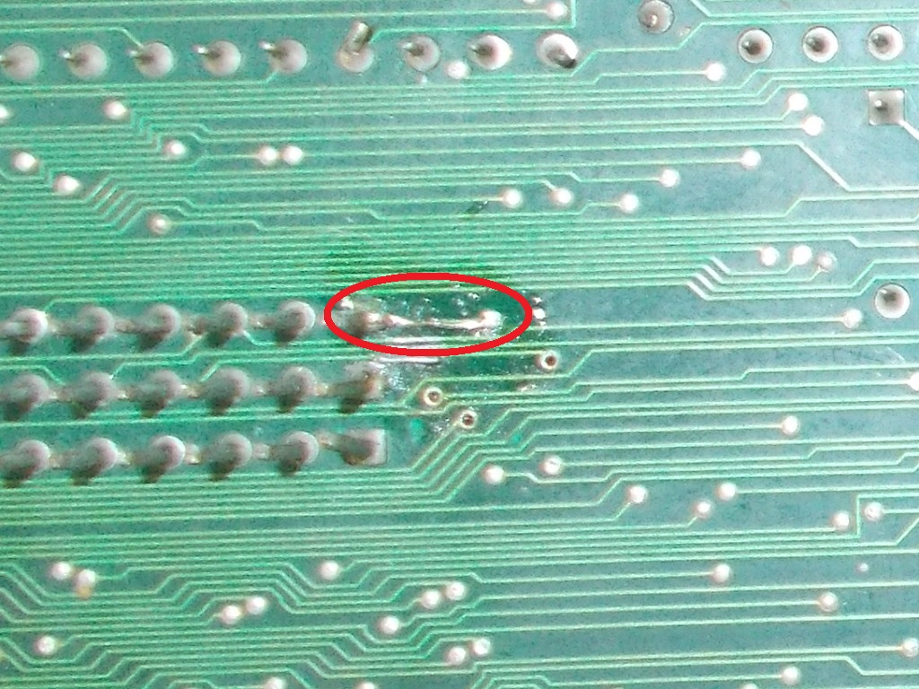
The repairs let assume a weakness and subsequent failure of the headers connections probably due to repeated disconnections and insertions of the ROM board.So I checked with a multimeter in continuity mode all the traces from the ‘CN1’ header and found another broken one that I promptly patched :

This fixed the graphics, no more jailbars on sprites :

Now the sound issue.

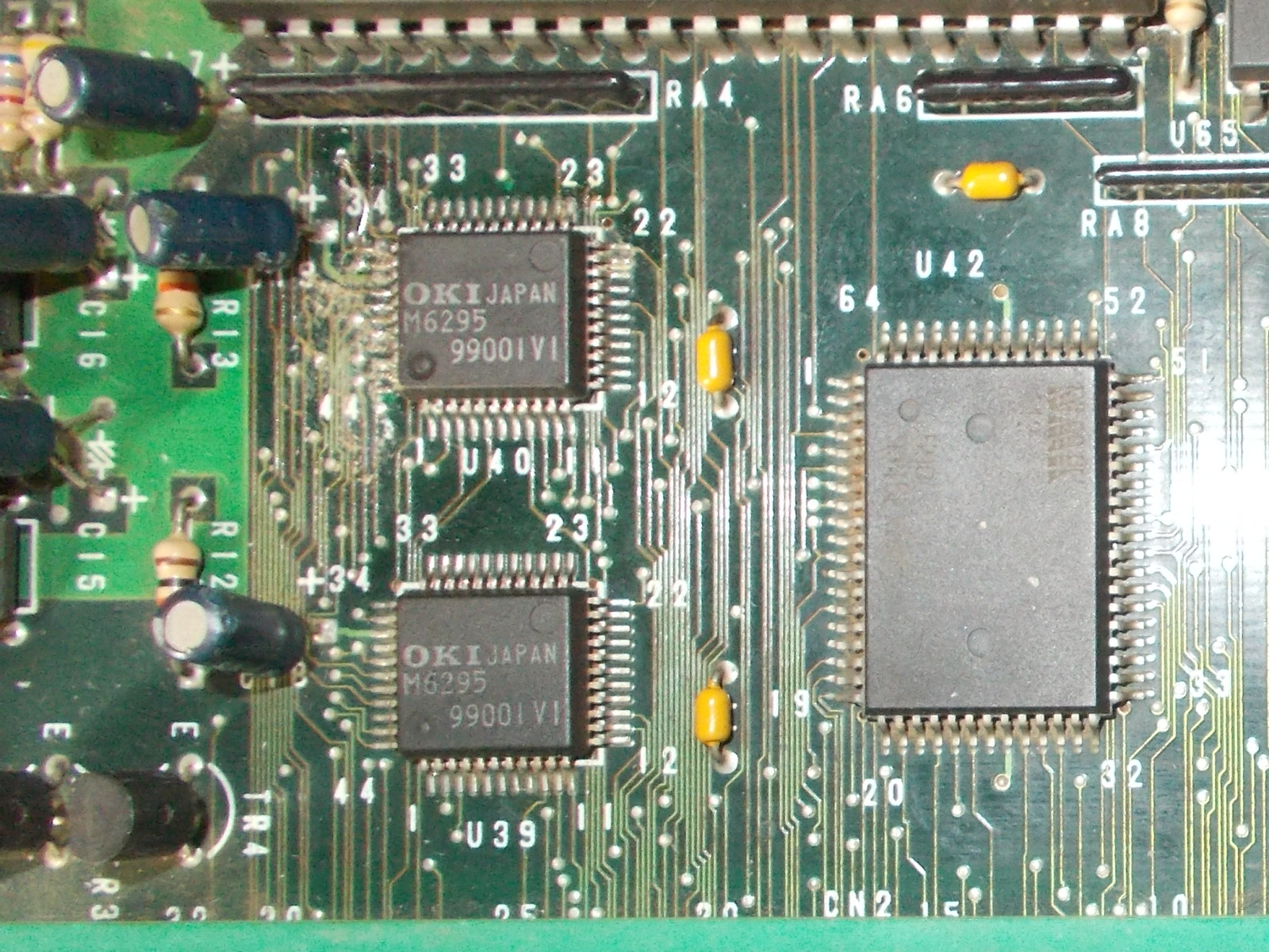
The audio circuit was previousy reworked, one of the OKI MSM6295 was likely replaced and one trace was repaired but this was not the culprit :

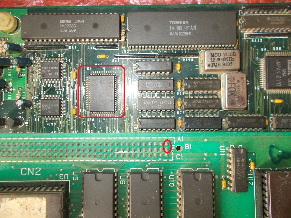
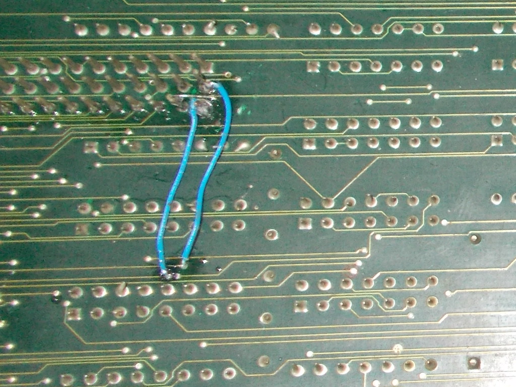
I noticed that if I pressed the ROM board on the ‘CN2’ connector some of the missing sounds were restored.I checked traces from ‘CN2’ to mainboard and found two missing connections to the ‘NMK112’ custom ASIC (responsible of  bankswitching the sample ROMs of the two OKI6295 ADPCM chips)

I patched the traces with some AWG30 wire:

Sound was totally restored and board 100% fixed.Repair accomplished.


 Posted by at 10:57 am

Apple IIe repair log – bad ram

 Computer Repair Logs, Repair Logs  Comments Off on Apple IIe repair log – bad ram
Aug 262019
 

I recently received this Apple IIe PCB from the U.S to try my luck on salvaging the 60hz IOU and using it in my International NTSC board in the hopes of getting colour which I did successfully in my previous post. This board was advertised as untested, so that normally means “DEAD” and I assumed so.


Taking one look at the RAM suggests there were issues in the past and most likely still issues. We have some original mT ( Micron ) / Apple branded DRAMs mixed in with the various replacements. Micron don’t exactly have the best reputation in regards to reliability so this is definitely a red flag. These were used by Commodore, Atari and obviously Apple as well. I guess they were cheap!


Based on the excellent condition of the board I was happy and confident in firing it up. It displays some kind of RAM error but it’s not very helpful, definitely not as helpful as the reporting in the Enhanced IIes built in diagnostic. I don’t have a choice but to go through and check each DRAM individually.


My TopMax helps me find 4 bad DRAMs of the 8. Three of which were Micron ( expected! ).


Dead RAM chips on the left clearly marked  to remind me that these are dead and not to be mixed up with working. These will come in useful for refining my Atari 8bit diagnostic tool.

I temporarily replaced the dead RAM chips with known good Micron pulls from my friends Atari 800xl. But I do have some NOS TMS 150ns chips that will be going in shortly.


Replacing the RAM confirms the fix.


It’s nice to have a second board ready to go if I need it, and the fact that it’s a non enhanced board with everything socketed is a plus.  I’ll be looking at converting this over to enhanced at some point via a enhancement kit which involves a 65C02 and newer roms for Apple IIc compatibility.


Apple IIe enhanced ( Platinum ) – NTSC 50hz to 60hz conversion

 Computer Repair Logs, Mods, Repair Logs  Comments Off on Apple IIe enhanced ( Platinum ) – NTSC 50hz to 60hz conversion
Aug 252019
 

The final revision of the exported Apple IIe and Platinums use the International NTSC PCB, this ships with a very odd 50 hz NTSC configuration. The stock motherboard is fitted with a 14.238Mhz and requires the original 50hz Apple IIe Color Monitor to display a non monochrome picture on the screen. A standard 60hz capable NTSC monitor or 50hz PAL monitor ( as expected ) fails to pickup the colour on these machines due to some odd Hybrid combination.

Unfortunately my Apple Color monitor has a dead flyback and all efforts to source a replacement or substitute part went nowhere so I had to find an alternative. One alternative is using a PAL / Color encoder card but these are rare and expensive whenever they turn up.

The theory to get colour involves changing the crystal at Y1 from 14.238Mhz to 14.31818MHz, this is logical and seems to work for most people who have tried this modification. One of the issues surrounding the crystal has already been discussed at length on the various forums, it must have an ESR of 25 ohms and not any off the shelf crystal will do apparently. Most people have had success using the specific type of crystal with the right characteristics, unfortunately I have not. After changing the crystal at Y1, I still had a black and white display on all my monitors ( Sony PVM, Philips & TEAC LCD  ) which are capable of displaying 60hz NTSC in colour.

The PVM and my Commodore 1084s PAL monitor ( Philips made ) had no issues with locking on to sync despite the black and white monochrome picture ( expected in the 1084s case ). My Philips LCD still interpreted the signal as PAL even after changing the main crystal. In fact the signal was not stable and both LCDs were struggling to lock on to sync permanently, with the picture slightly shimmering or going completely out of sync for at least half a second ( as in the TEAC’s case ).


This has left me scratching my head as it appears that ALL my monitors were very picky , yet other people had success.

The Technical Reference Manual, in chapter 7 states that the IOU ( input / output unit ) handles and generates the video signals, video blanking, horizontal  signals via some internal counters.

http://www.applelogic.org/files/AIIETECHREF3.pdf

There are several different versions of the IOU but information out there is rather confusing and in some cases incorrect and that’s something I’d rather not cover at all. The NTSC International and even the PAL models use a very specific version of the IOU not found in the non export, U.S versions.

  • IOU 344-0022 ( used in International NTSC 50hz and PAL models ).
  • IOU 344-0020 ( NTSC 60hz ).

I had an idea to swap out the original 344-022 IOU for the 344-0020 and I took my chance on a non tested earlier IIe PCB.  Thankfully only 4 RAM chips were bad ( mostly Micron, surprise surprise! ) which I’ll cover in my next repair log. I very carefully remove the original IOU, installed a machined pin socket and swapped the IOUs over. The original IOU still works in the other IIe after all that surgery ( Phew! ).

At some point later on I had to replace the RAM as well most likely caused by accidentally handling static prone devices without an anti-static wrist strap ( whoops! ). Not to worry, I have plenty of spares.


The results with splendid colour on my PVM!


And a valid NTSC signal on my Philips LCD ( Karateka in action! )


Conclusions: It was suggested the possibility that the original IOU was damaged or partially faulty ( I have to keep that in mind ) but I’ll never know unless someone else confirms the same or I can get my hands on another IOU ( 344-0022 ). I previously had the same exact issue in another IIe before I sold it, however I was using FOX143-20 branded crystals ( which have an ESR of 40 ohms ) at the time rather than the proven to work ones below which have an ESR of 25 ohms.  I still have my FOX crystals on hand, so at some point I’d like explore those again and see if colour is still possible given I’ve swapped the IOU over to the 60hz version.


The following crystals have been proven to work.  Still no colour on your International NTSC board  ? Try a different IOU by substitution.

ECS-143-S-1

ECS-143-S-1X.

These can be found at the link below.

https://www.digikey.com/products/en?keywords=ECS-143-S-1