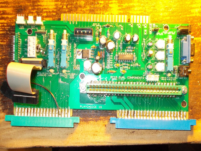
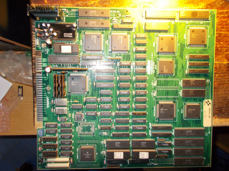
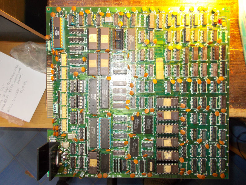
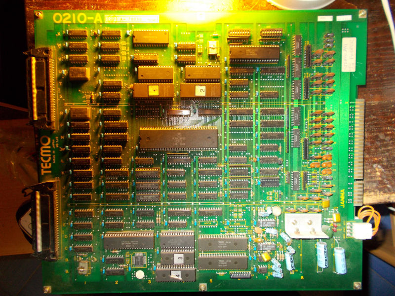
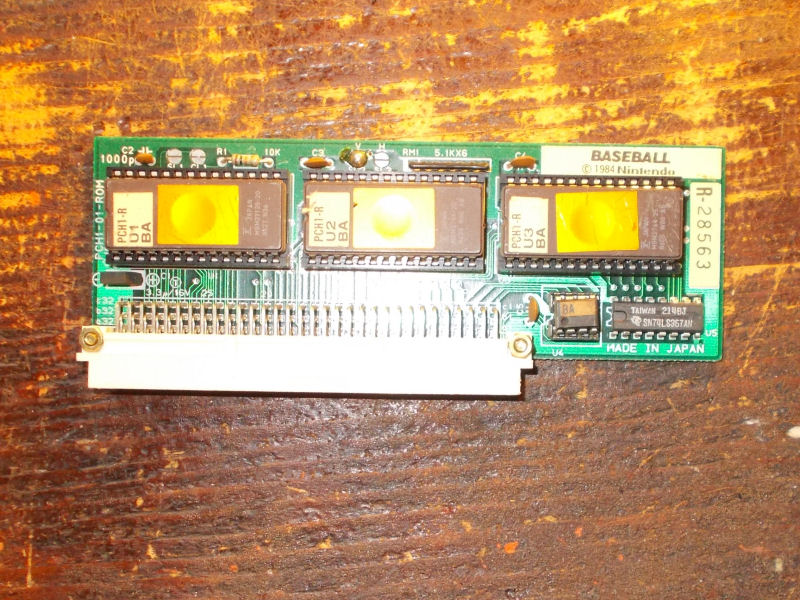
I got this board from my friend Joachim for a repair.A Nintendo Playchoice-10 system:
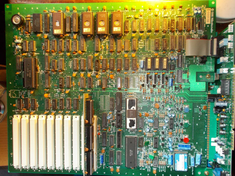
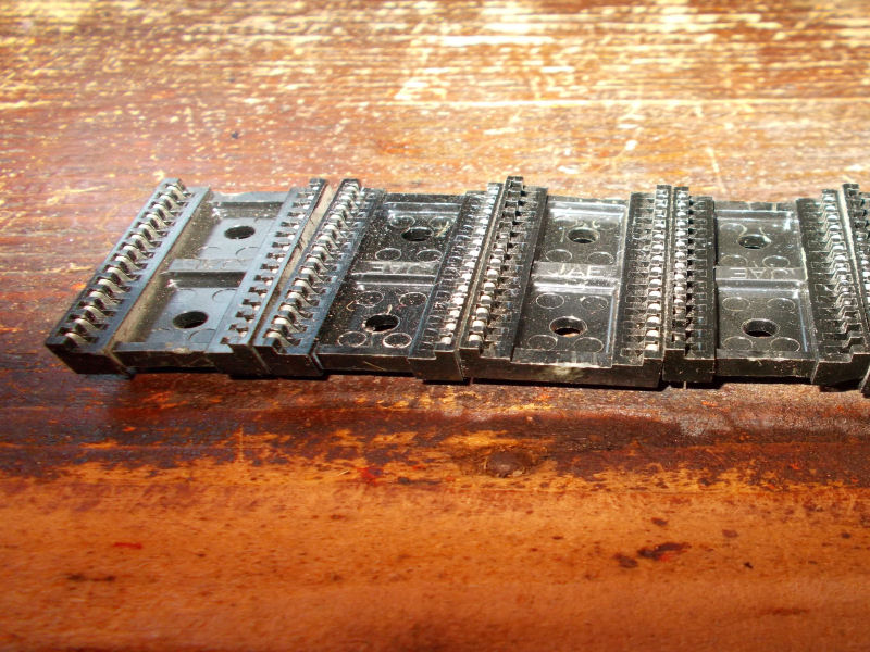
For the uninitiated, Playchoice-10 is the arcade hardware developed by Nintendo to run its most popular NES games inside an arcade cabinet.The games for this system are in the modular form of carts which are plugged into one of the ten open slots on the PlayChoice-10’s motherboard:
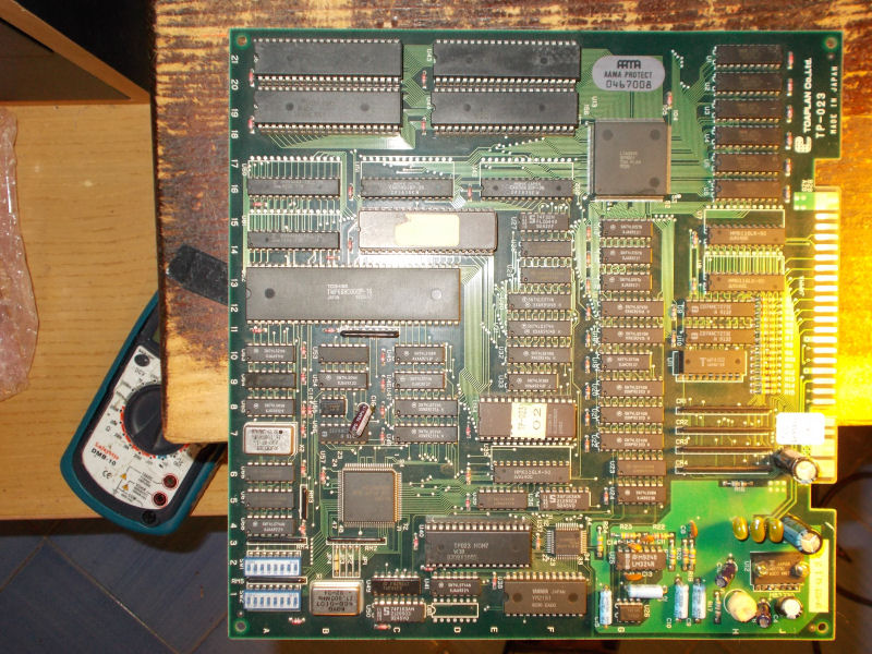
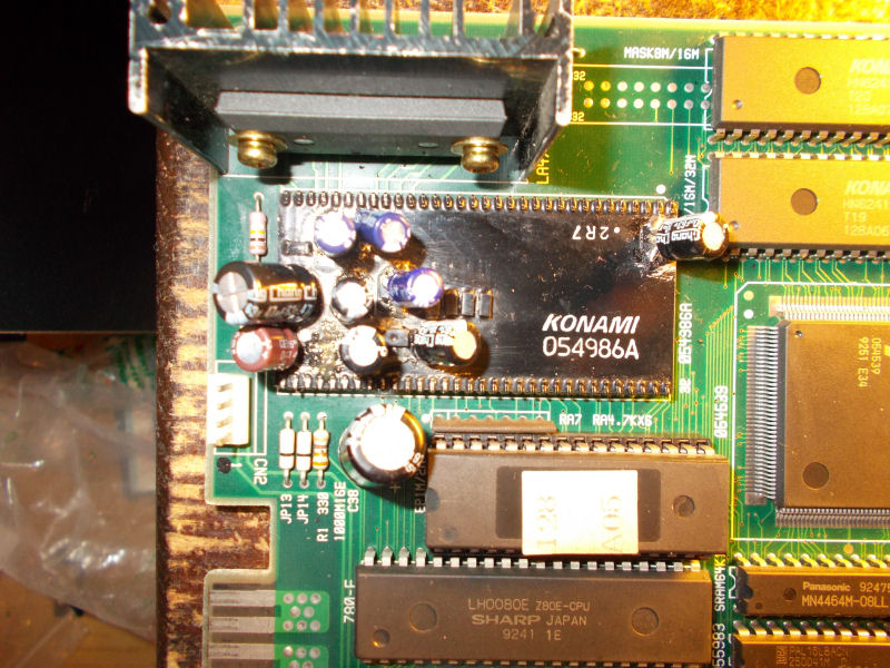
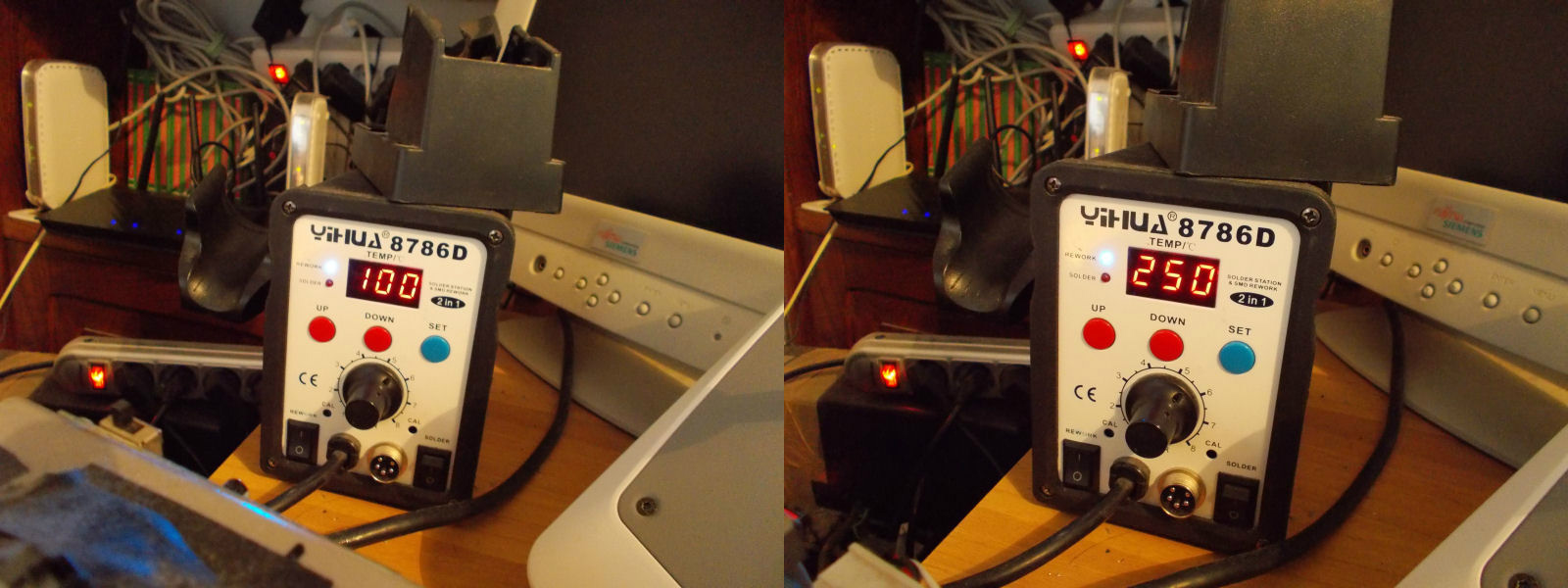
When I first powered it up, I was greeted by a solid black screen, no activity on main Z80 CPU.A closer inspection revealed a missing 8MHz crystal @X1 which supplies the clock to main CPU:
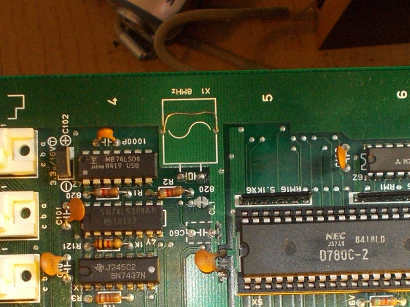
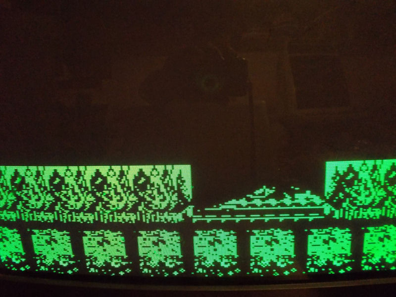
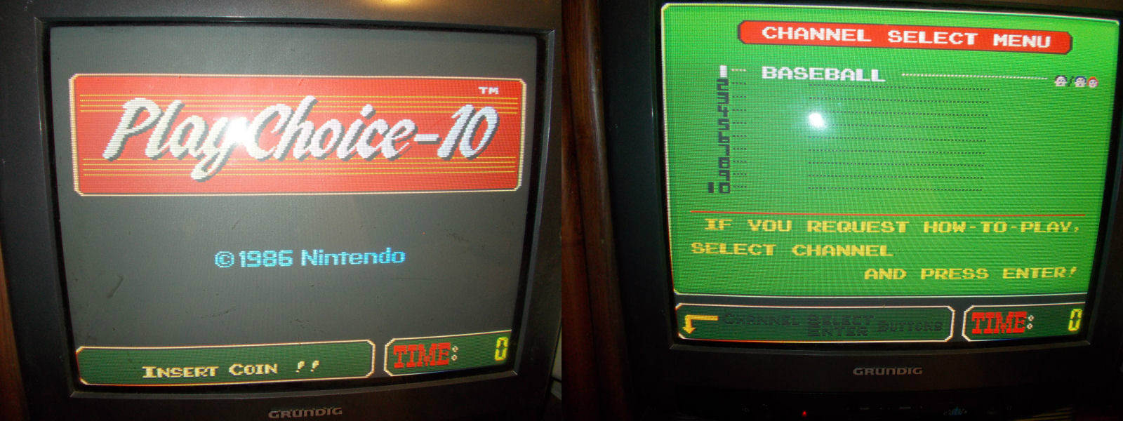
Once fitted a new crystal I had clock signal on pin 6 of the Z80 but the watchdog circuti was active ( /RESET line was constantly going to HIGH to LOW state in a endess loop).I pulled the Z80 and tried it in a good board having confirm it was faulty.With a good CPU all I got was a green screen:

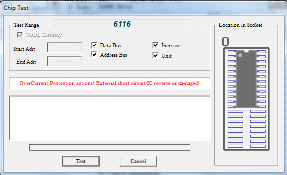
While probing chips I came across a TMM2115 (6116 compatible) RAM @4K which was burning hot to the touch, I remove it and my programmer reported it as shorted:
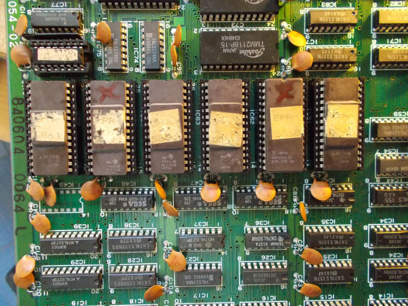
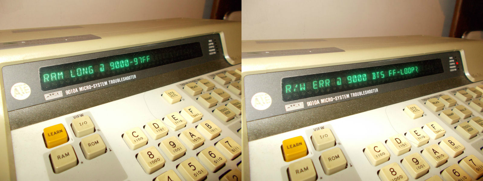
With a good RAM I got always that green screen but could hear sound sign that the board was playing ‘blind’.This was a good chance to use my Fluke 9010A troubleshooter.MAME reported this memory map:
0000 – 3fff = Program ROM (8T)
8000 – 87ff = RAM (8V)
8800 – 8fff = RAM (8W)
9000 – 97ff = SRAM (8R – Videoram)
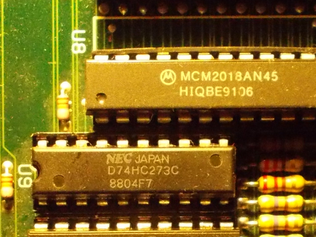
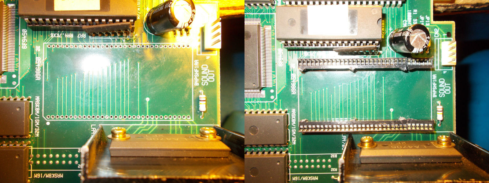
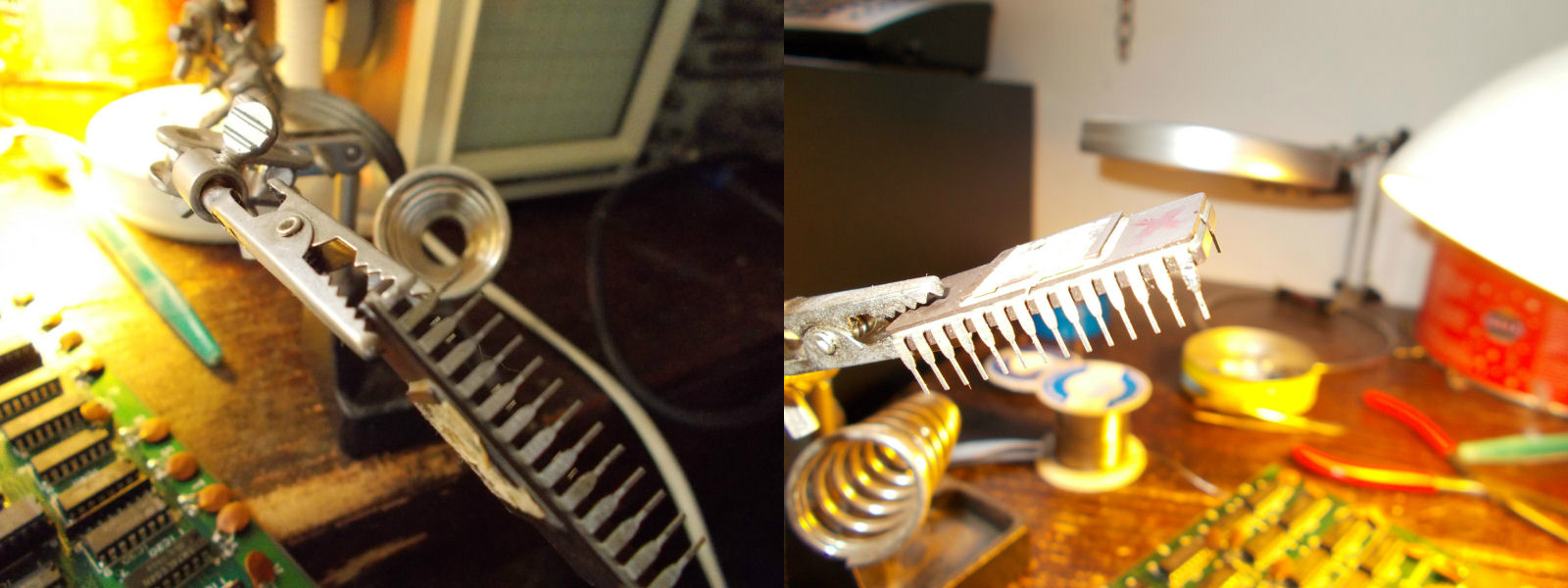
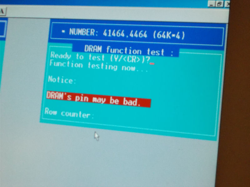
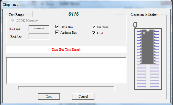
I could successully perform a RAM LONG test on address space of RAM @8V and 8W but I got an error on the videoram @8R (all these RAMs were 6116 compatible):
Once removed, the chip failed the out-of-circuit test:
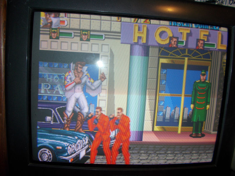
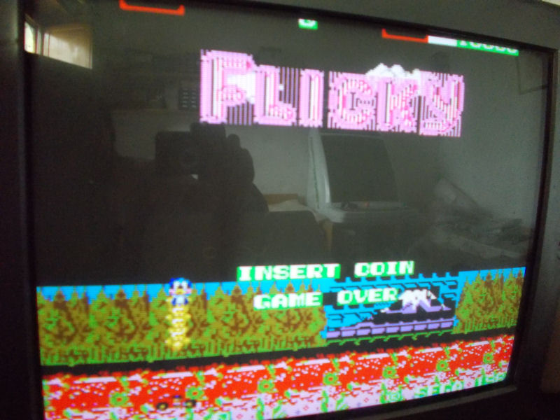
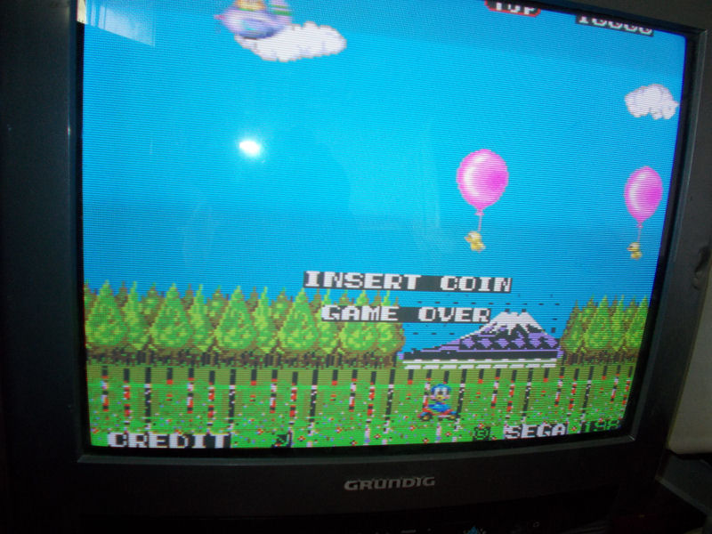
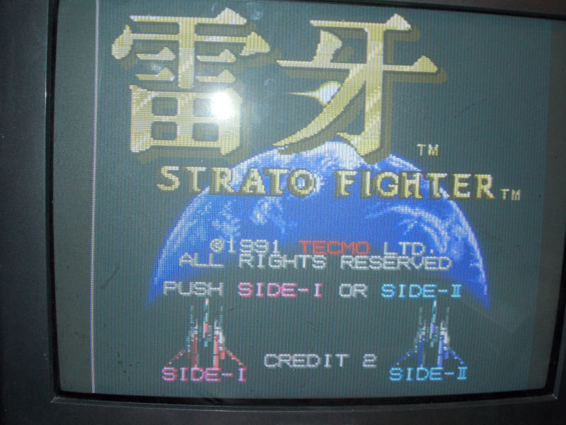
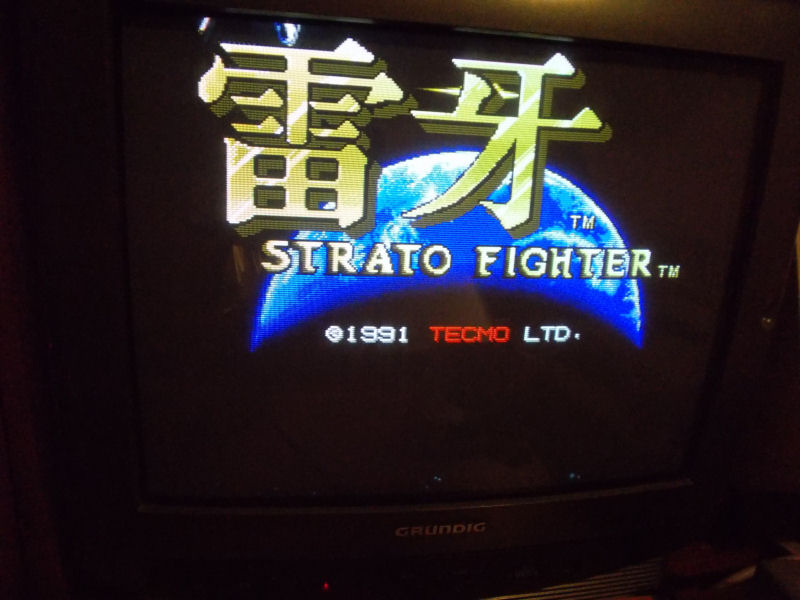
Finally I got it running:
but, since the motherboard (PCH1-01-CPU) was a dual monitor type, I could not display the playfield (although it came with this JAMMA adapter which provides also outputs for a second arcade or VGA monitor)