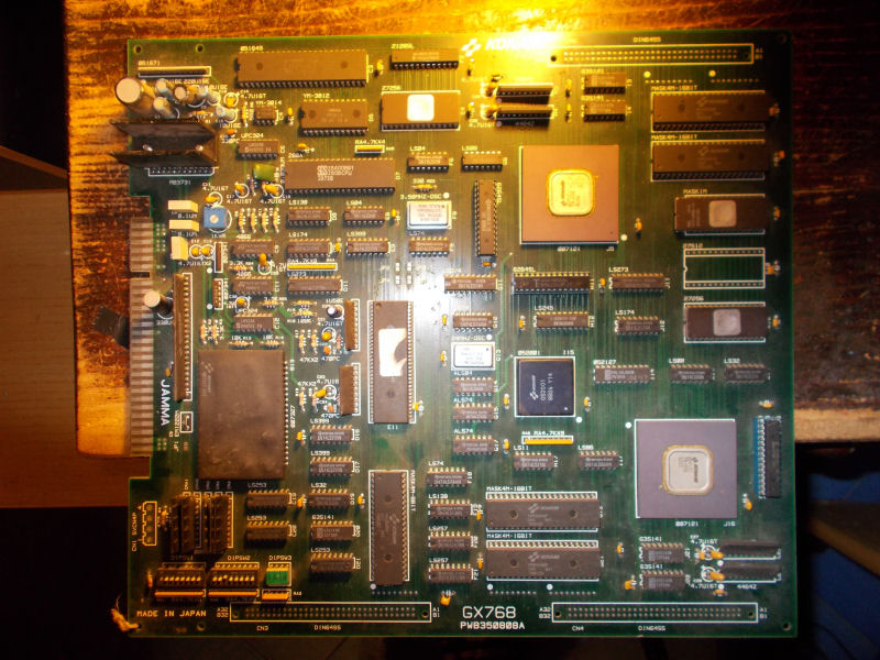
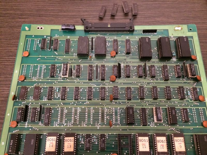
I got this original namco untested pcb as a part of a deal.
As always happens, untested =not working and infact upon booting up it was totally dead with only a fixed static screen.
I was not too worried because I had a Dig Dug by Sidam which I use for spare parts and there are also schematics available (by Midway).
So I began my troubleshooting.
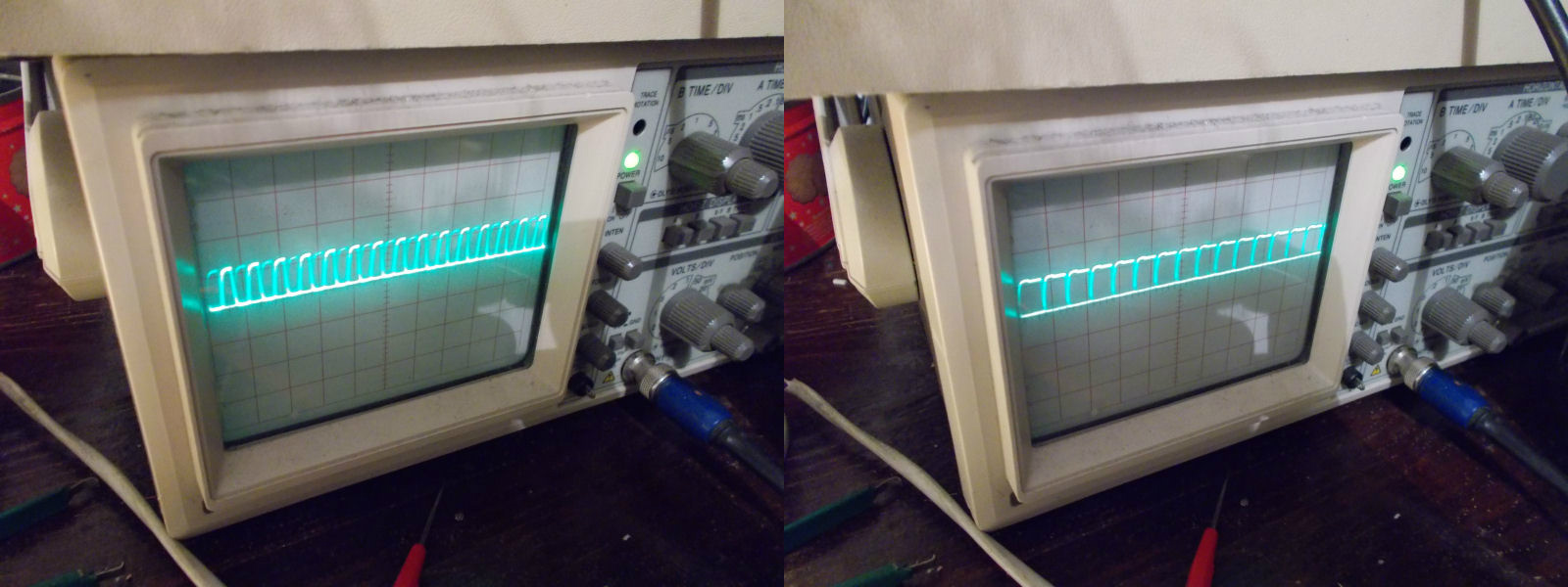
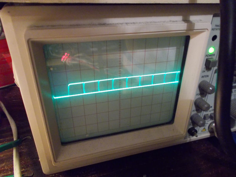
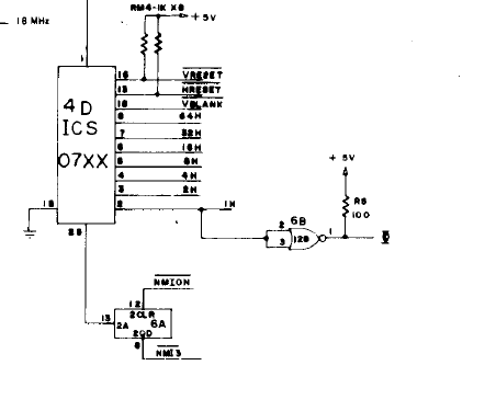
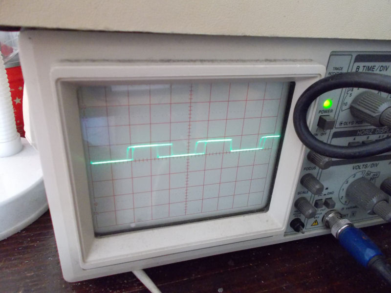
I checked the clock on the 3x z80s and it was missing.
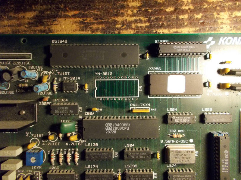
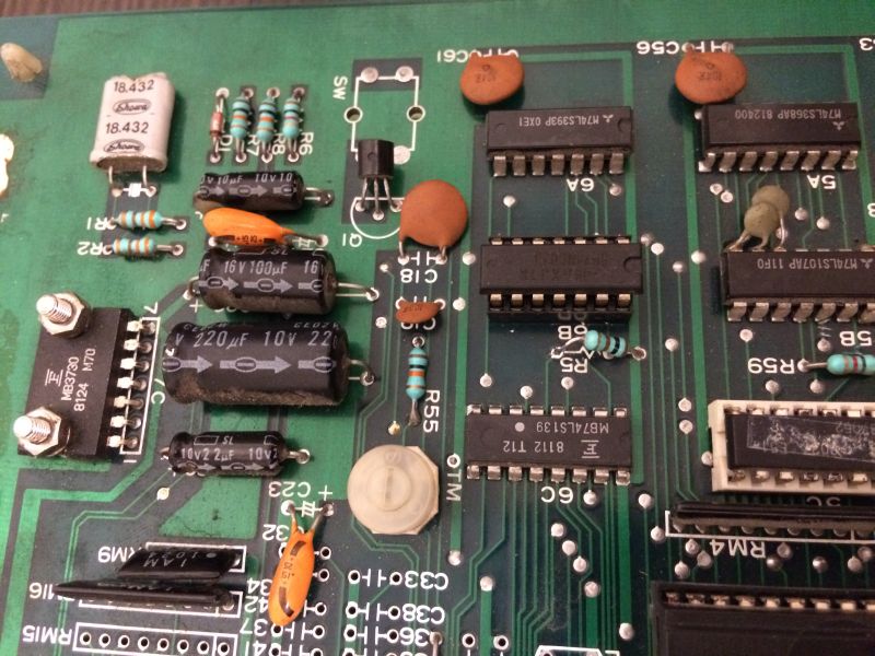
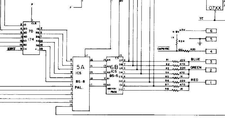
Traced back to a dead output of a 74128@6B. The input coming from custom 07xx was OK.

I started to search for a replacement and I took my Dig Dug pcb but in place of the 74128 there was a socketed 7402.
Bad luck, someone put wrong TTL as a place holder….
I then discovered that this 74128 is not common at all and it is used only on early namco pcbs.
I decided to contact my friend Charles Mcdonald to have a suggestion how to make the pcb boot just at least to see if it hadn’t other faults.
He told me that this 74128 is a really weird choice because it is used to drive signals over long distances and a 7402 is the equivalent to drive lower mA, but I had to disconnect the R5 100ohm resistance.
In the end the guys at SIDAM made this “modification” on purpose to the original Namco design!
So I fixed the clock problem installing a 7402 and lifting provvisorily the resistance.

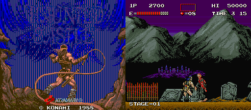
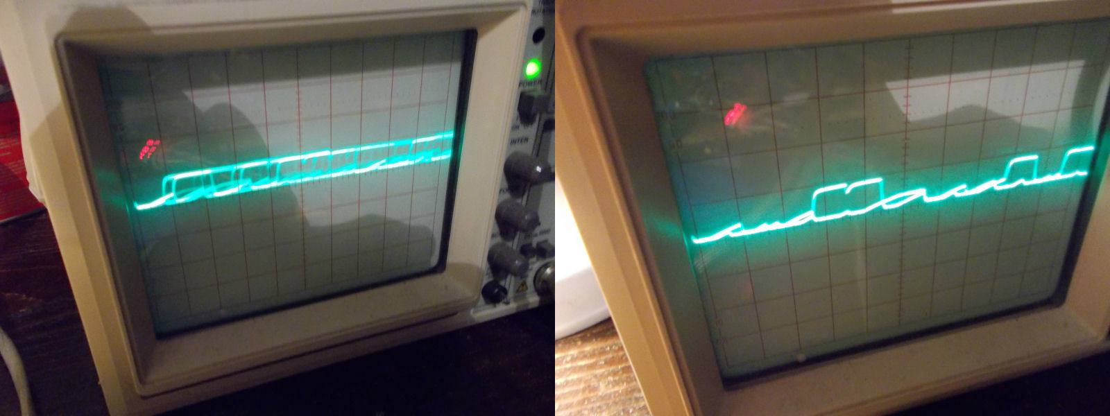
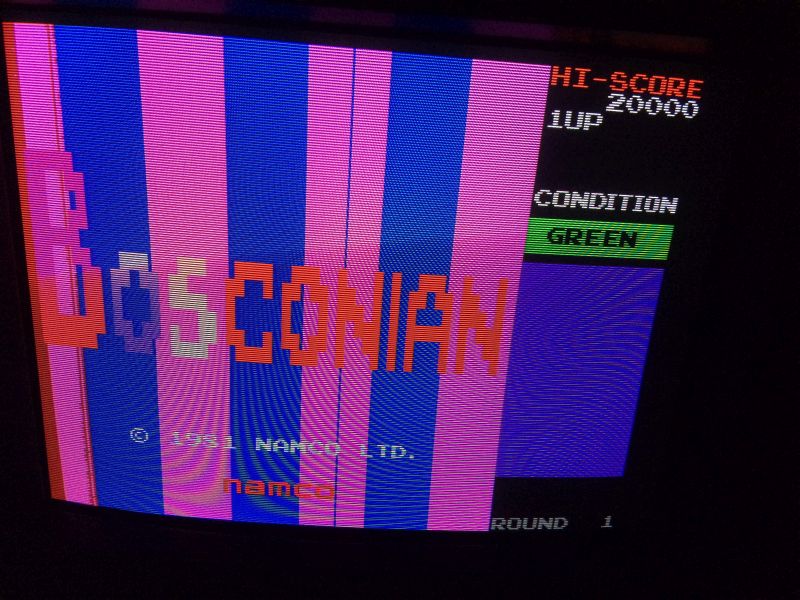
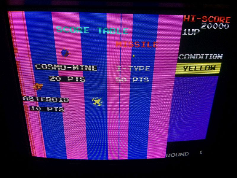
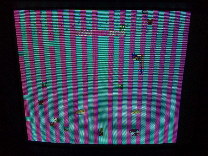
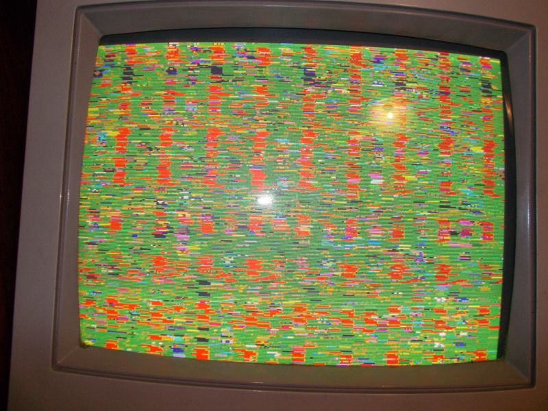
After booting up, unfortunately the game had another issue:
After some studying of the pcb schematics and some short circuiting I discovered that beneath these stripes there was the black background with the
stars correctly generated by the custom.
Worth of note is the score part of the display that was good.
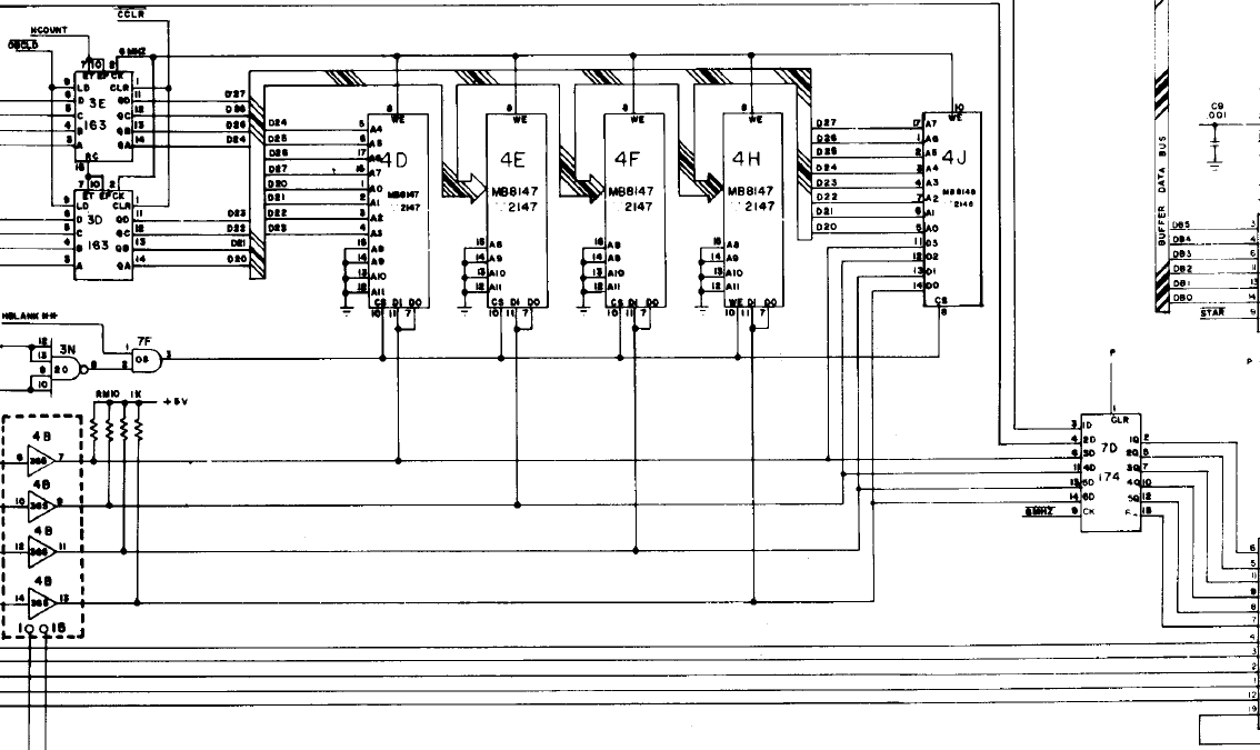
On the video pcb there were 4x 4kx1bit rams 2147 which I didn’t have as spares (Dig Dug uses another video board) , two of them were running very hot .
Tested with the logic probe they were pulsing correctly.
At this time it was clear that the problem came from around there because shorting some pins changed the coloured stripes.
Disabling the CS line of the rams, restored good backdrop, stars and enemies but your ship and missiles disappeared.
So it was clear that these stripes where the “scattered” colours which should have been combined to make the ship correctly coloured.
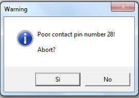
I decided to test with the logic comparator the 74174@7D which is mixing the bits from the rams : it reported some bad pins.

When I changed it I got no better results, but I got another positive feedback that the problems came from the circuit near the rams.
If I left out completely the chip from the socket I got good backdround and no ship.
The enemies and bases are part of the background circuit.
All the TTL which were used to address the rams were good so it was clear that some or all the 4x 2147 rams were bad.
At this time I decided to give up and to order some new rams in the hope that the problem was really there.
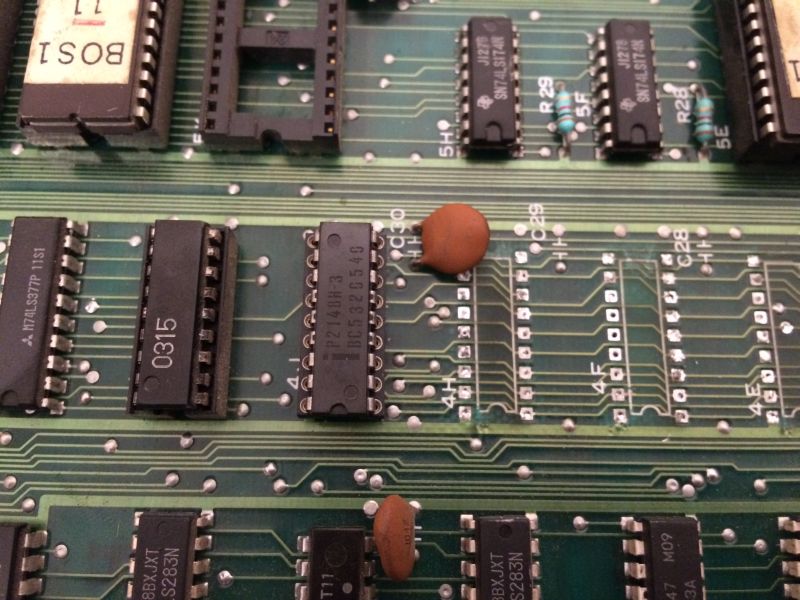
Just before placing the order I decided to take another look at the 2148 ram @4J which on my pcb was not placed and I thought of a schematic mistake.

Now everything was clear : Namco prepared already the pcb to accept one 2148 ram which is 1k x 4bit instead of 4x 2147 rams, 4 k x 1bit !
The highest addr lines are not used so it can really be used as a replacement!
I had a lot of 2148 rams so I immediately desoldered all 4x 2147 rams and placed @4J the 2148 ram
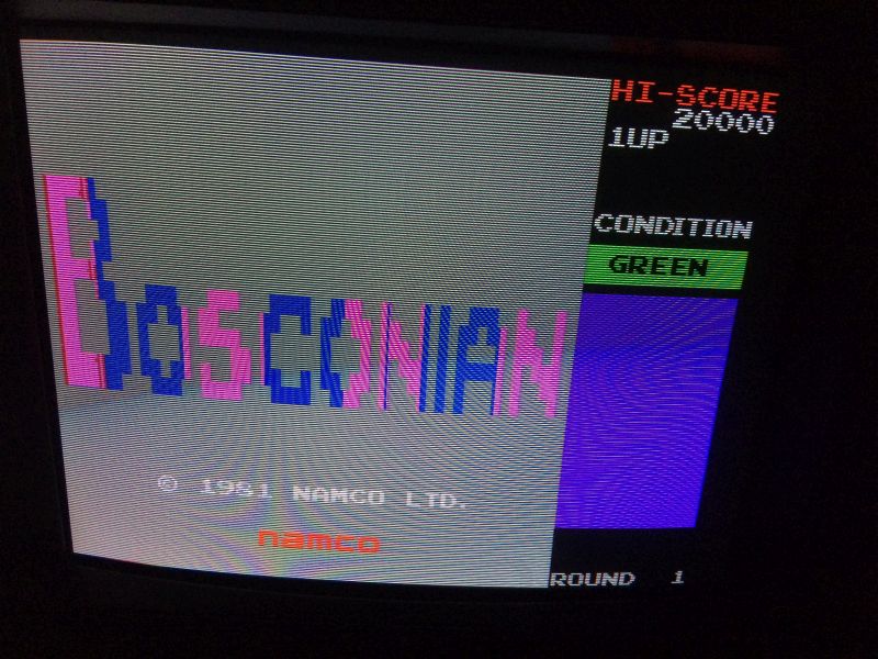
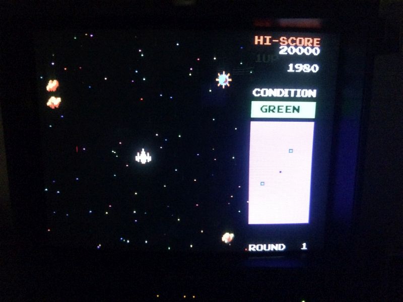
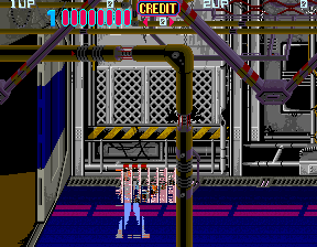
Finger crossed and when the game booted up I was finally welcomed with correct colours!