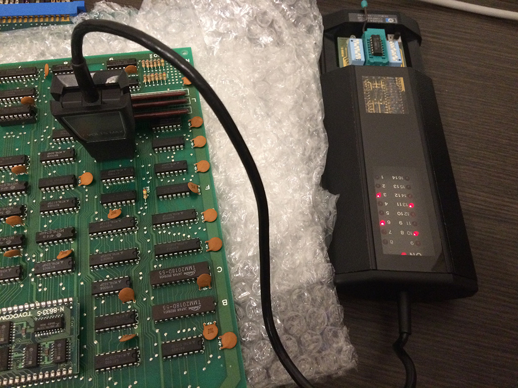
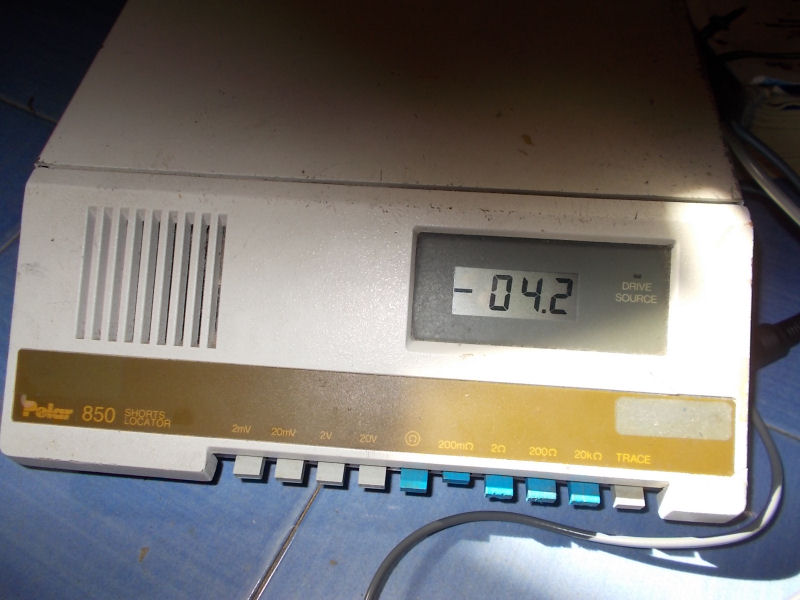
Last week I bought on Ebay an untested Polar Toneohm 850 (picture from Internet) :
For the uninitiated this is a instrument that is able to locate quickly and accurately shorts on PCBs.Device is essentially an audible milliohmmeter which, indeed, produces a tone whose frequency is inversely proportional to the resistance measured across its probes.The more you get closer to the short and so the lower will be the resistance, the higher will be the produced tone.This is very useful when you come across a PCB with a dead short or small resistance between VCC and GND, using a normal multimeter would have no effect since you will end up to measure always same resistance values due its accuracy (most if times of 0.1 ohm ) which is too coarse.
So, I bought this kind of equipment which arrived me a couple of days ago.When I saw the package, I immediately had a bad feeling :
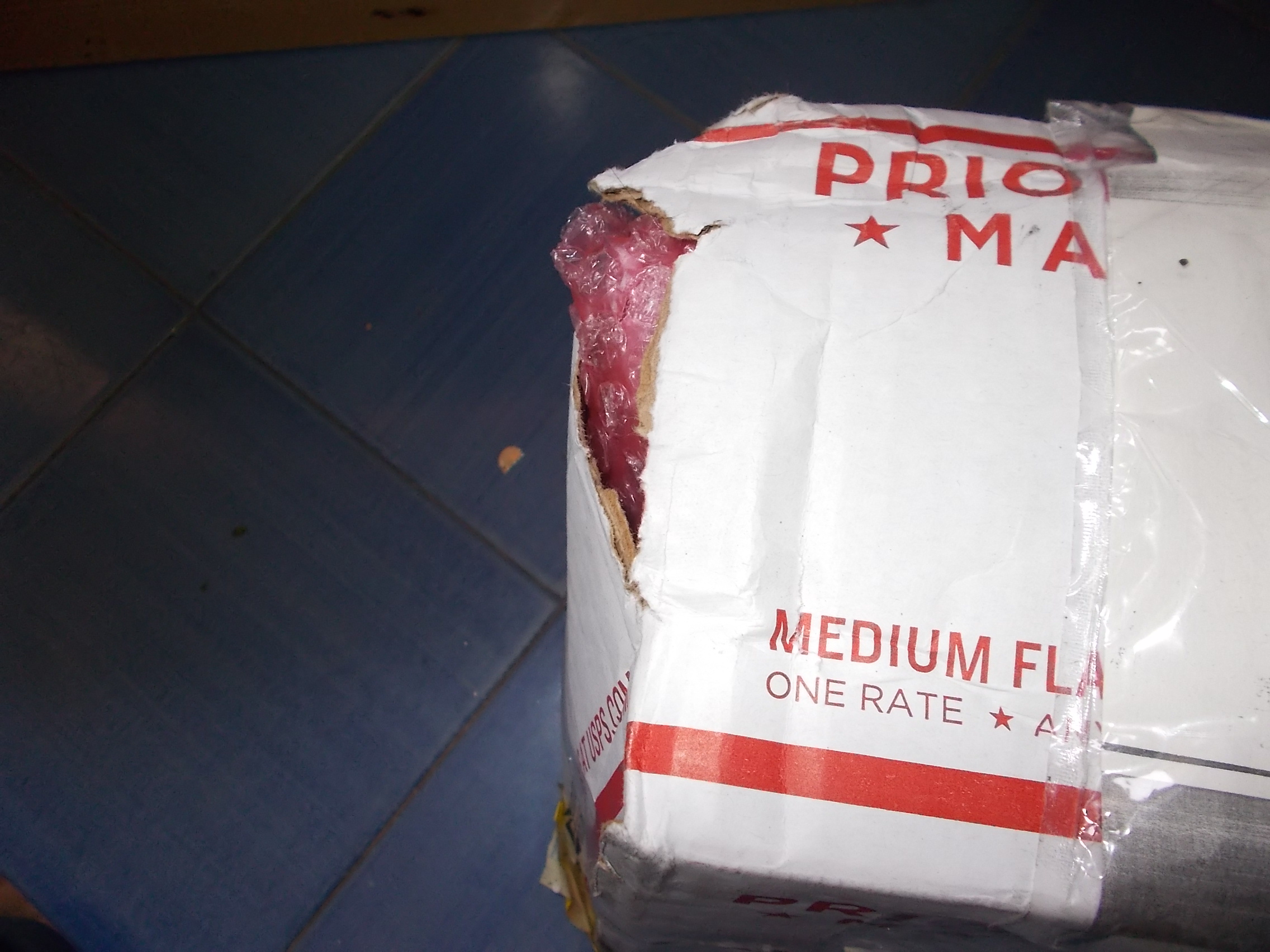
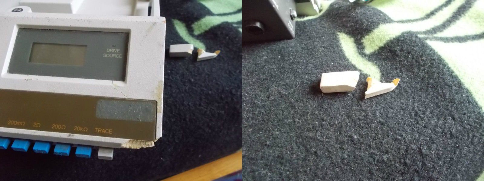
The box was broken and, once opened, the case of the unit too:
But worst , the unit didn’t power on at all, it was competely dead while the seller clearly stated (sending me also a picture) that, although untested, instrument turned on showing numbers on display.
Since I needed this piece of equipment I opted for repairing it instead of asking for a refund and send it back.
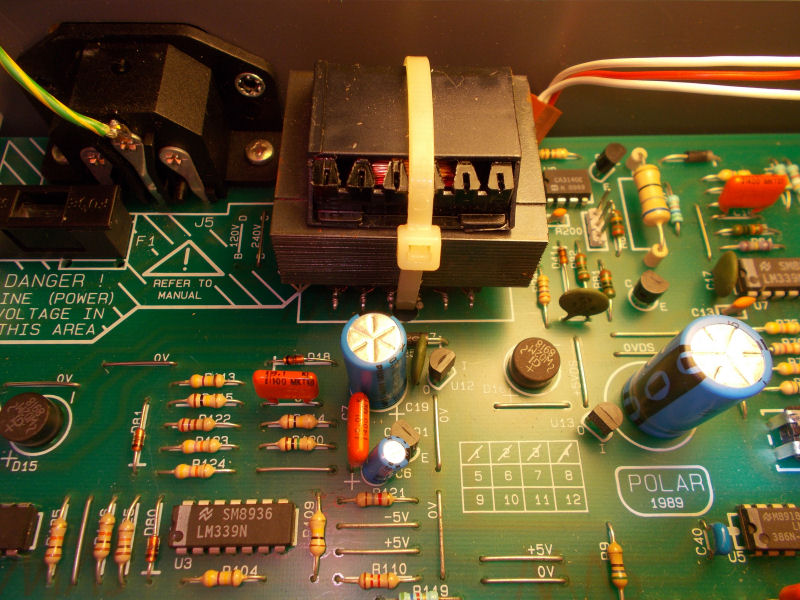
I opened the unit and PCB was in untouched state, no sign of damage or burn components.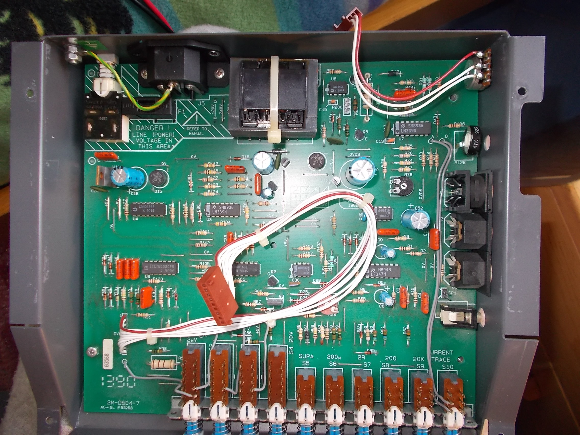
First of all I went to check voltages on the various test points, I could only measure few Millivolts.Thanks to the user ‘Fraser’ (thanks again!) on EEVblog forum I got schematics of this specific model so I could start my troubleshooting more confident.Design of the unit is quite simple : the 220VAC ( unit came with 120VAC line selected so had to change it accordingly to my country) reaches the main transformer ‘T1’ being reduced to 9VAC then it got rectified by a couple of bridges and then regulated by a 7805 and couple of 78L05 providing power for all the logic :
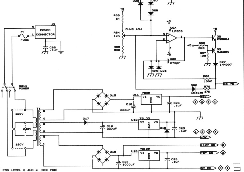
Again, I was able to measure more or less +1V on the inputs of the tree voltage regulators so problem was upstream, specifically in the main transformer (‘T1’ on schematics) :
Said simply, a transformer is a device made of a primary winding and one of more secondary windings.Windings are usually wound around very high permeability ferromagnetic cores.A varying current in the transformer’s primary winding creates a varying magnetic flux in the core which is transferred to the secondary windings by magnetic induction.
![]()
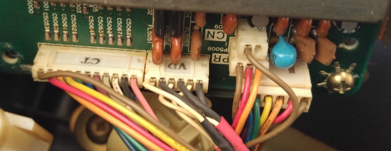
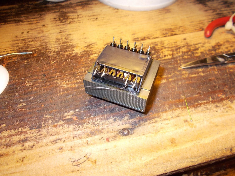
So, my problem was clearly located in the windings.I removed the transformer:
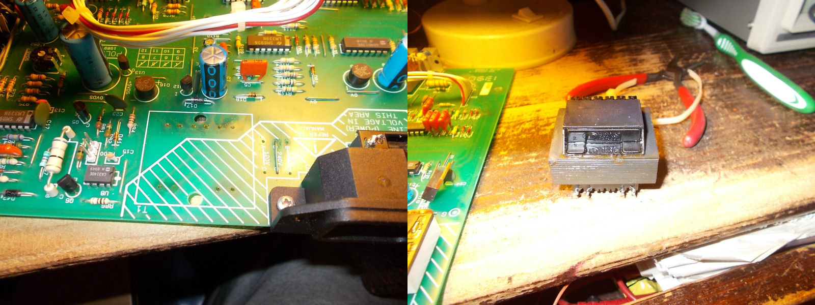
I went to check windings with my multimeter and none of them gave me resistance values, they were almost all opened due the shock received during shipping!But luckily they were interrupted just near the pins, see picture of primary ones for example :
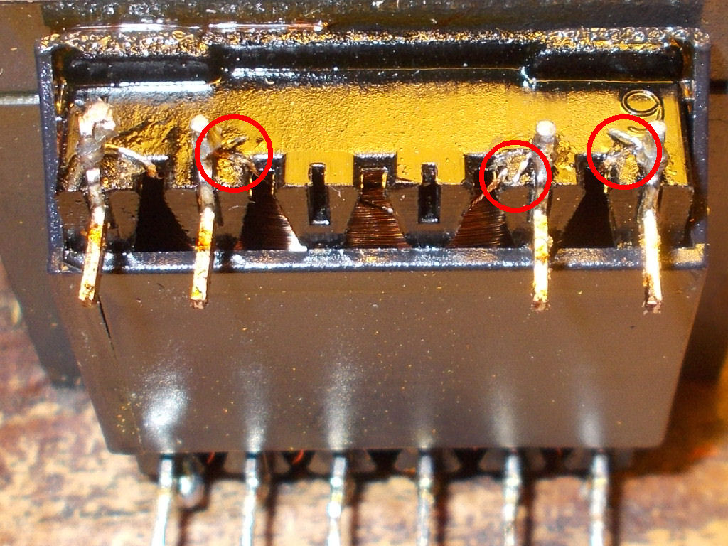
A bit of ‘surgery’ was needed using some AWG30 wire to restore all connections (part in excess of wire was cut, obviously)
Once mounted the transformer and reassembled all the pieces, the unit came back to life fully working!
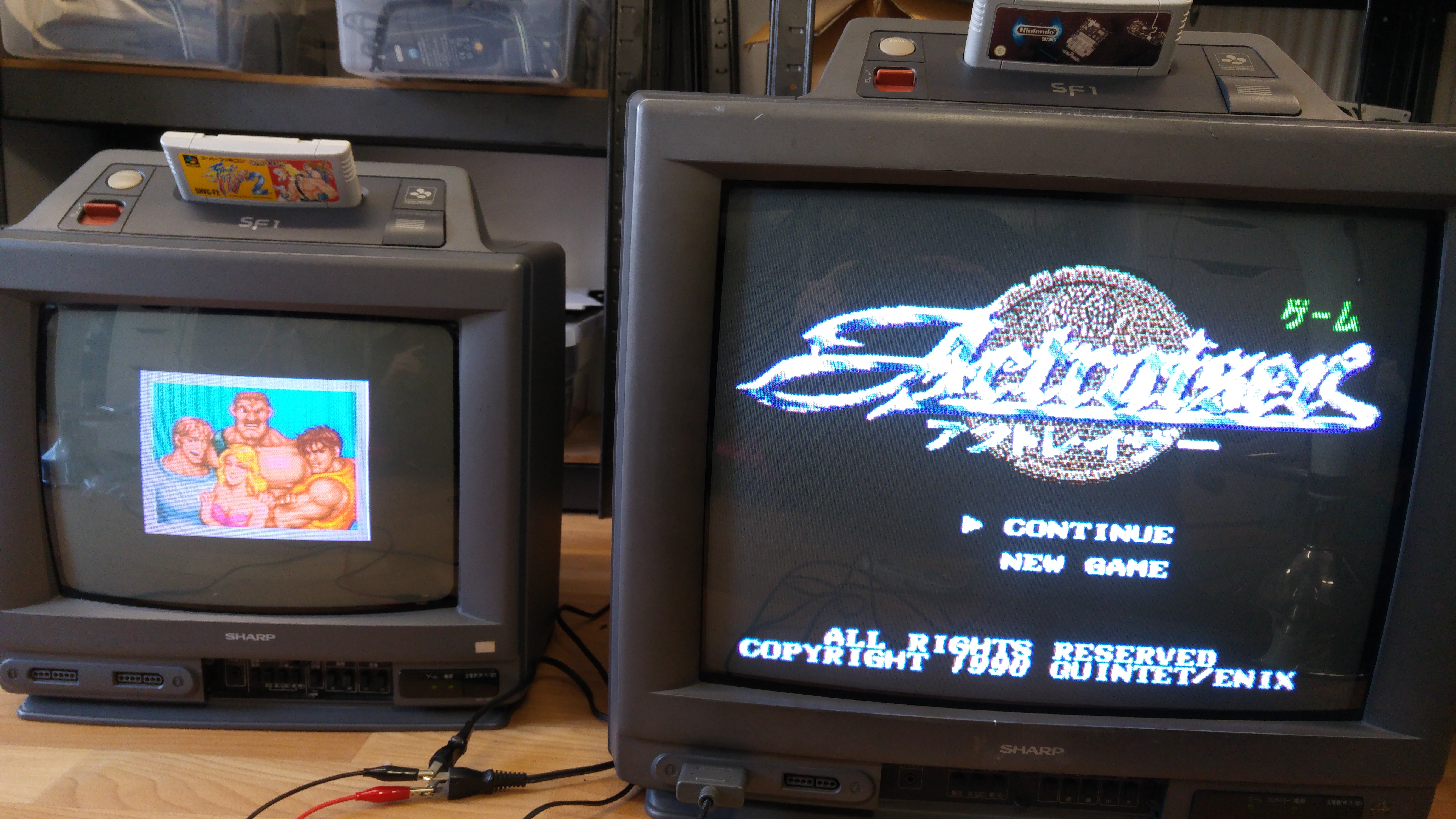
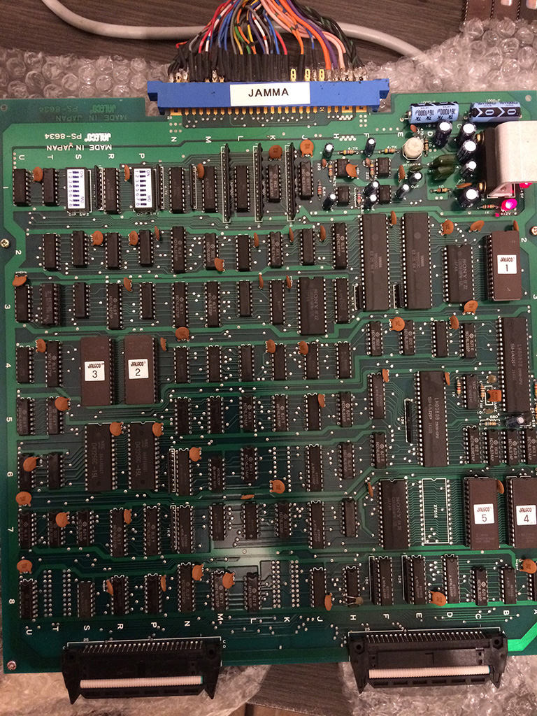
Video below shows a testing on an arcade board where a 100nF by-pass ceramic capacitor was intentionally shorted: