Oct 152016
 

Got a bunch of boards from Olly to attempt to repair. One of them is a tiny New Zealand Story PCB.
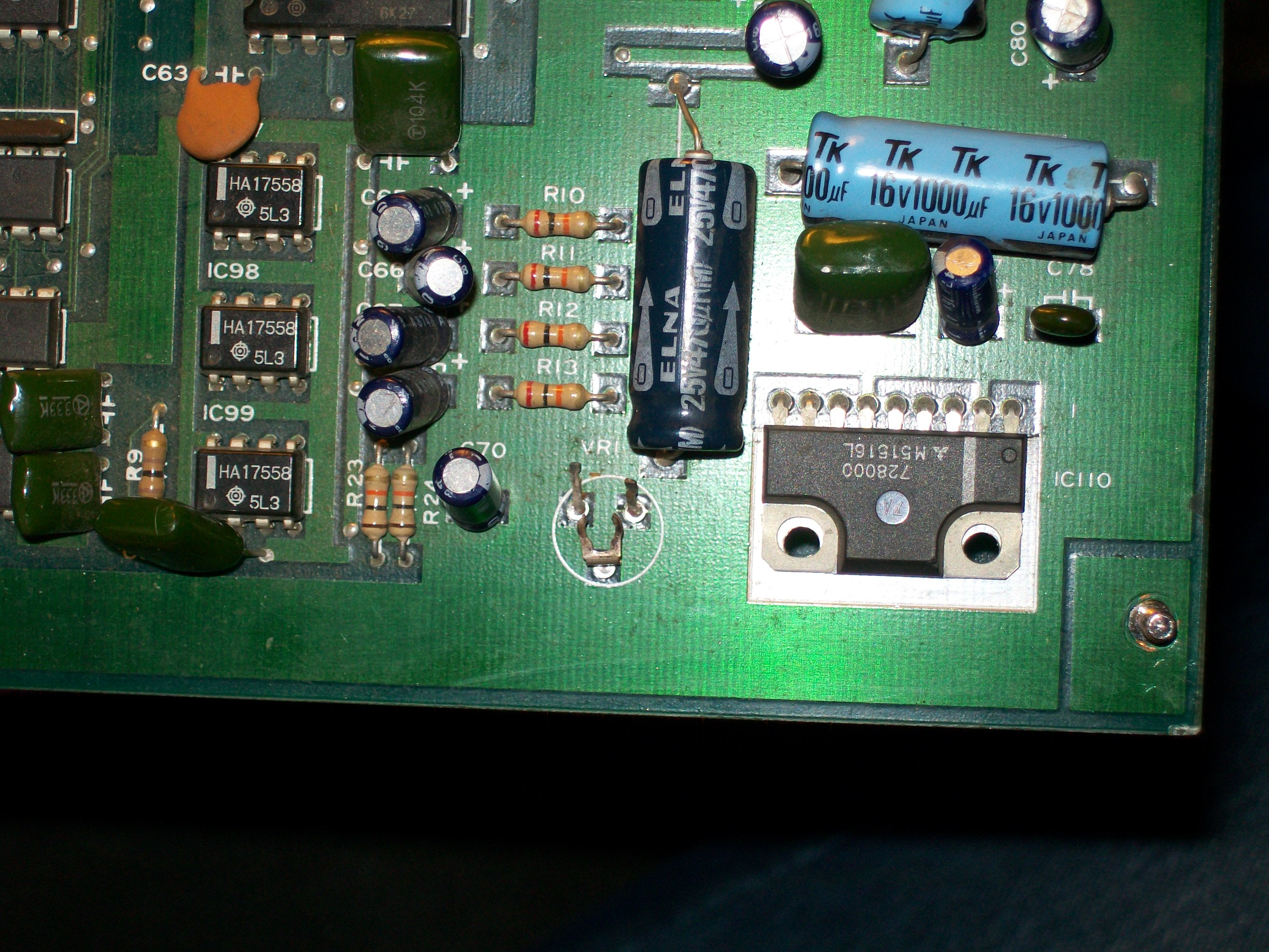
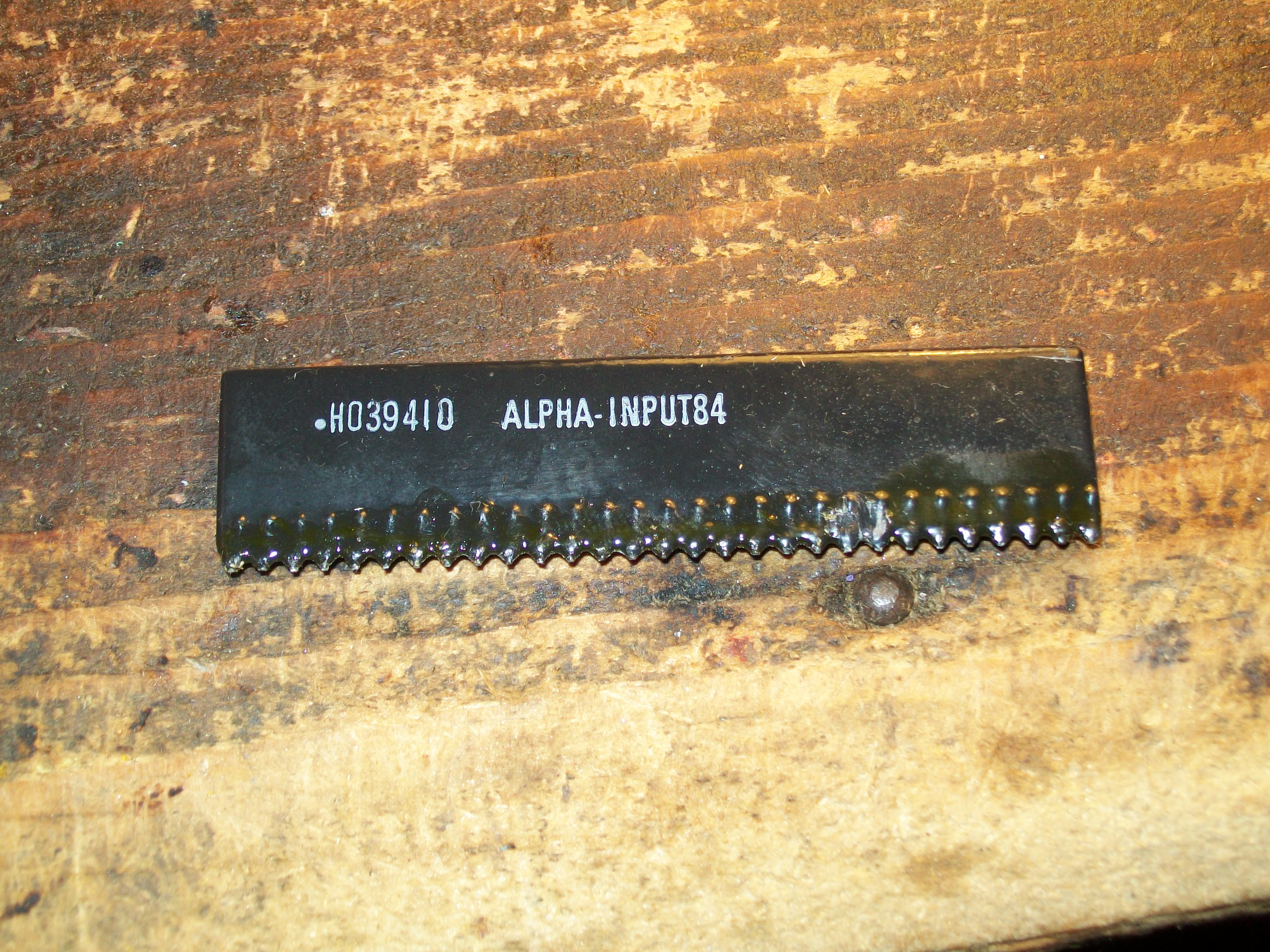
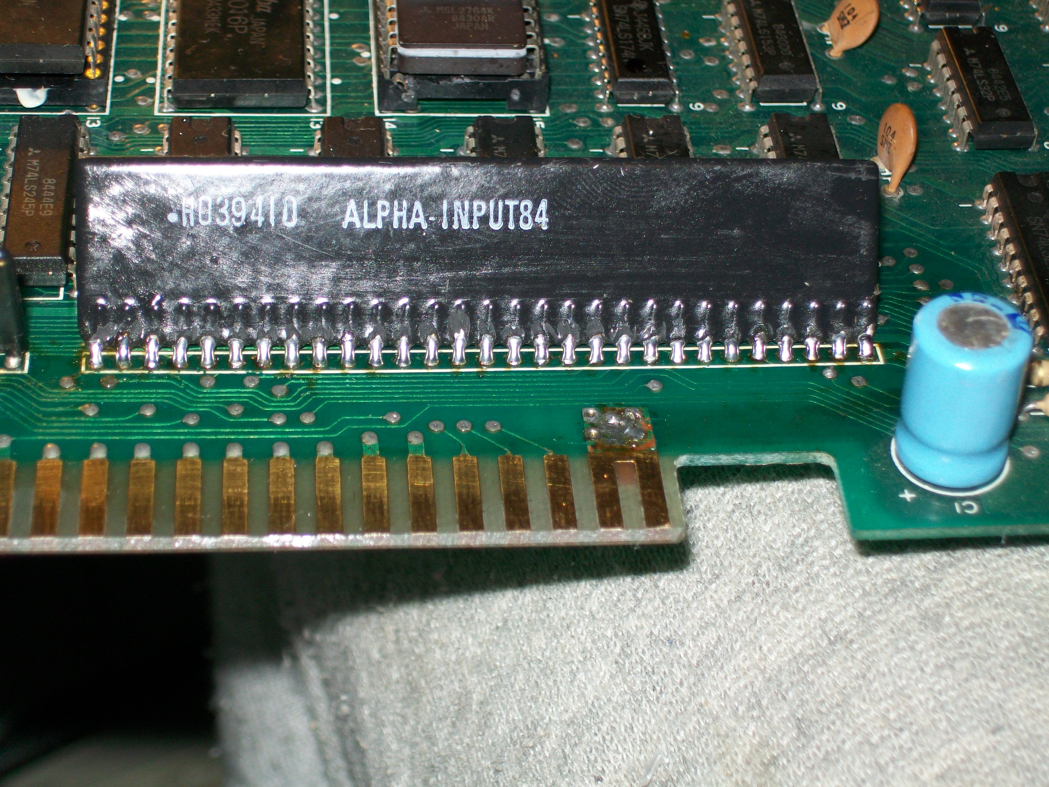
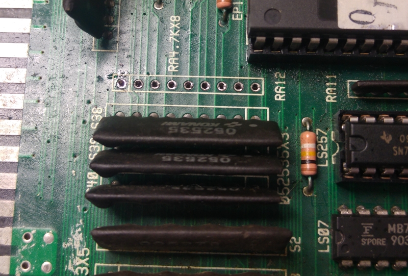
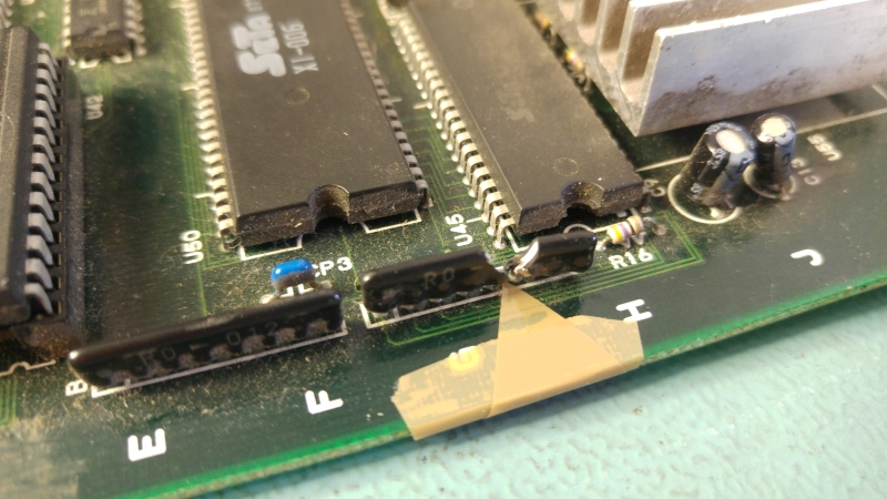
There is a broken custom resistor array on this PCB. Turns out this SIP is for DAC for the green colours.
20161001_113351

Not really sure how this could have happened. Caius is sending me a replacement for it but it plays no further part of this repair.
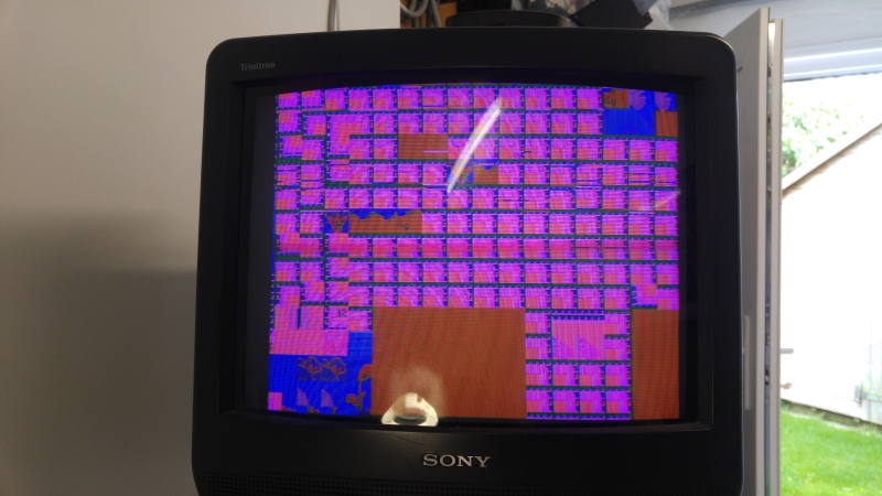
I powered up the PCB and this is what we get
20161001_113057

The game plays blind behind this wall of garbage so we know the CPU is doing its job.
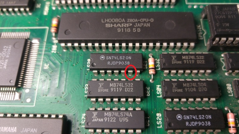
The board has quite a few Fujitsu TTL chips on it so my first bets were on failed TTL. The PCB is also tiny which makes this job pretty quick.
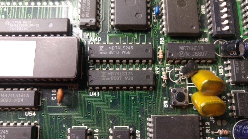
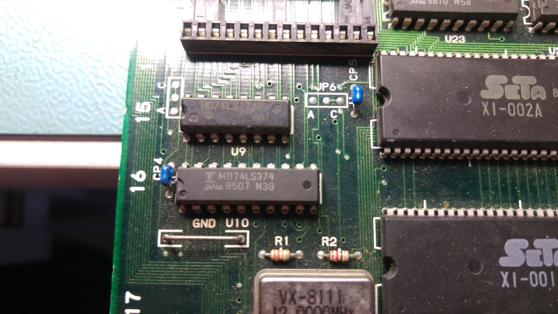
In my experience of failed Fujitsu chips I found that pins go completely dead and this PCB was on different. I found a couple of 74LS374 chips at U41 and U10 with dead outputs and these are easy to spot with a logic probe.
20161008_163239
20161008_163311

As the outputs were dead I could quickly test by ‘piggybacking’ a known good chip on top of it. The changes were good enough to confirm.
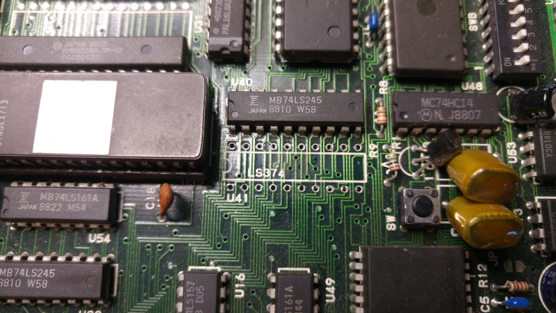
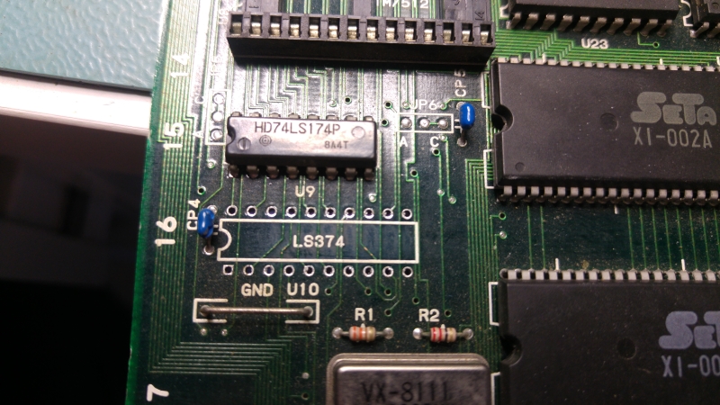
I replaced these two chips.
20161008_163840
20161008_163828

Replacing them did give a big difference and I could now see all the outputs from those two chips were once again active. The graphics were all messed up still.

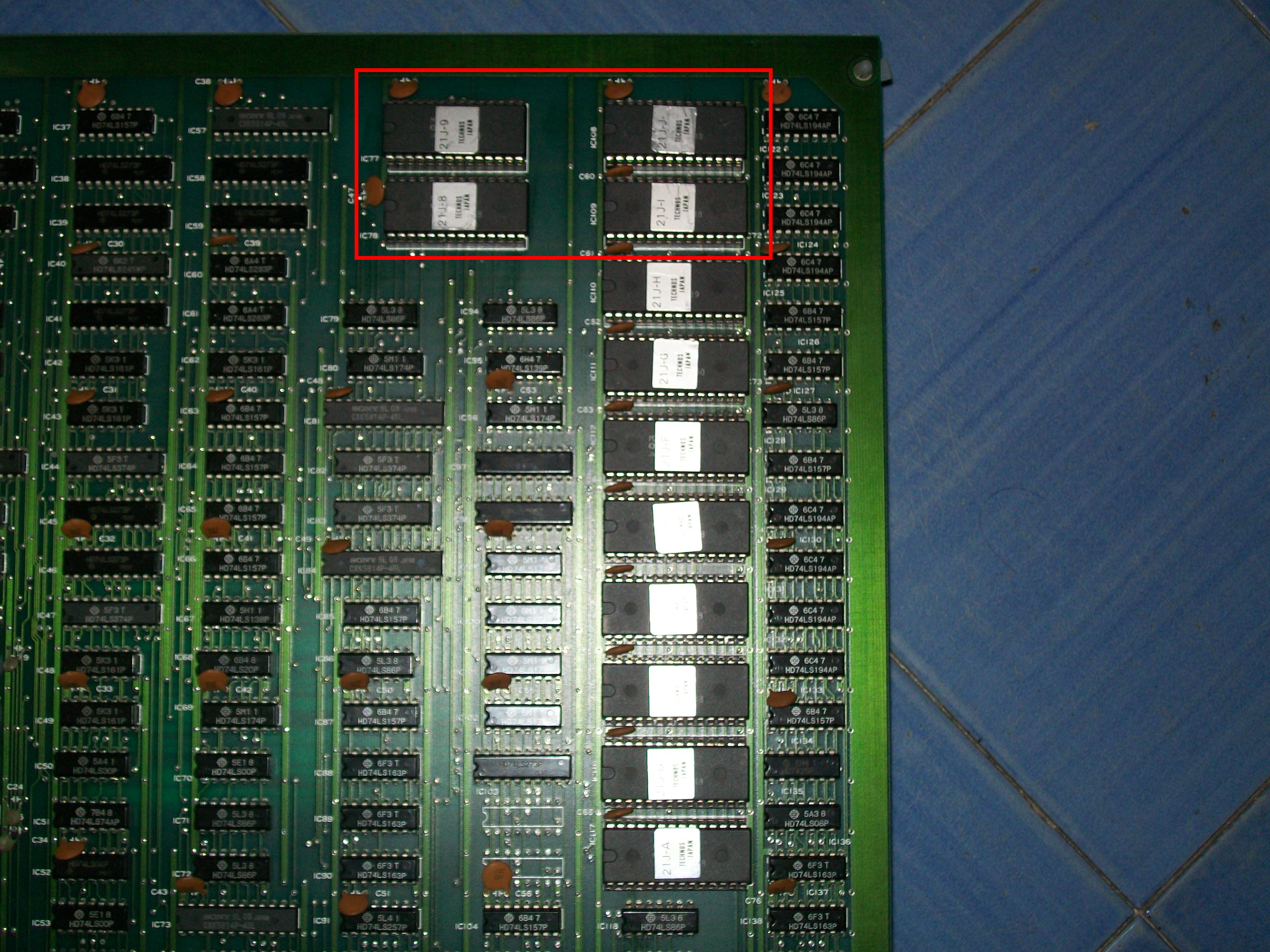
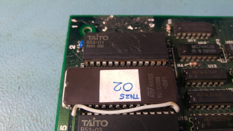
Next I see that one of the MASKROM’s has been replaced. They are 23C1000 compatible and therefore there is no 28 pin EPROM replacement available. It has been replaced with modified a 27C1000 chip.
20161001_113142

This mod is not part of the problem.
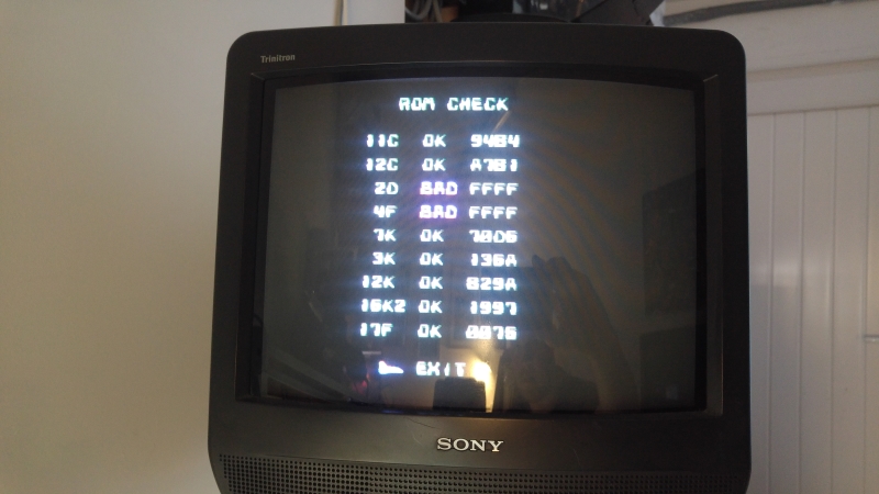
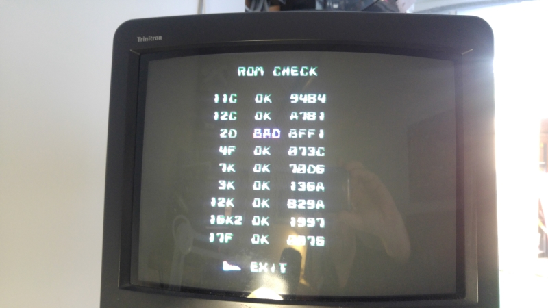
I pulled all the other MASKROM’s and dumped them. 4 of them actually failed so in the short term I replaced them with modified 27C301 EPROM’s.
All the graphics came back good.

There is a 128×8 ROM replacement PCB available from OSHpark shared projects made by system11 so I downloaded the Eagle board file, added a little TNZS graphic to it and ordered some up. The A298010AV chips however are really quite hard to source so Ive got to wait until February before these come in from back order!

As it stands now the game is fully playable with only the green colour issue. I will replace the resistor array SIP once it gets here.

 Posted by at 12:47 pm

Wonder Boy repair log #1

 PCB Repair Logs  Comments Off on Wonder Boy repair log #1
Oct 132016
 

Got this Wonder Boy (on Sega System 1A board revision) for a repair:

100_9079

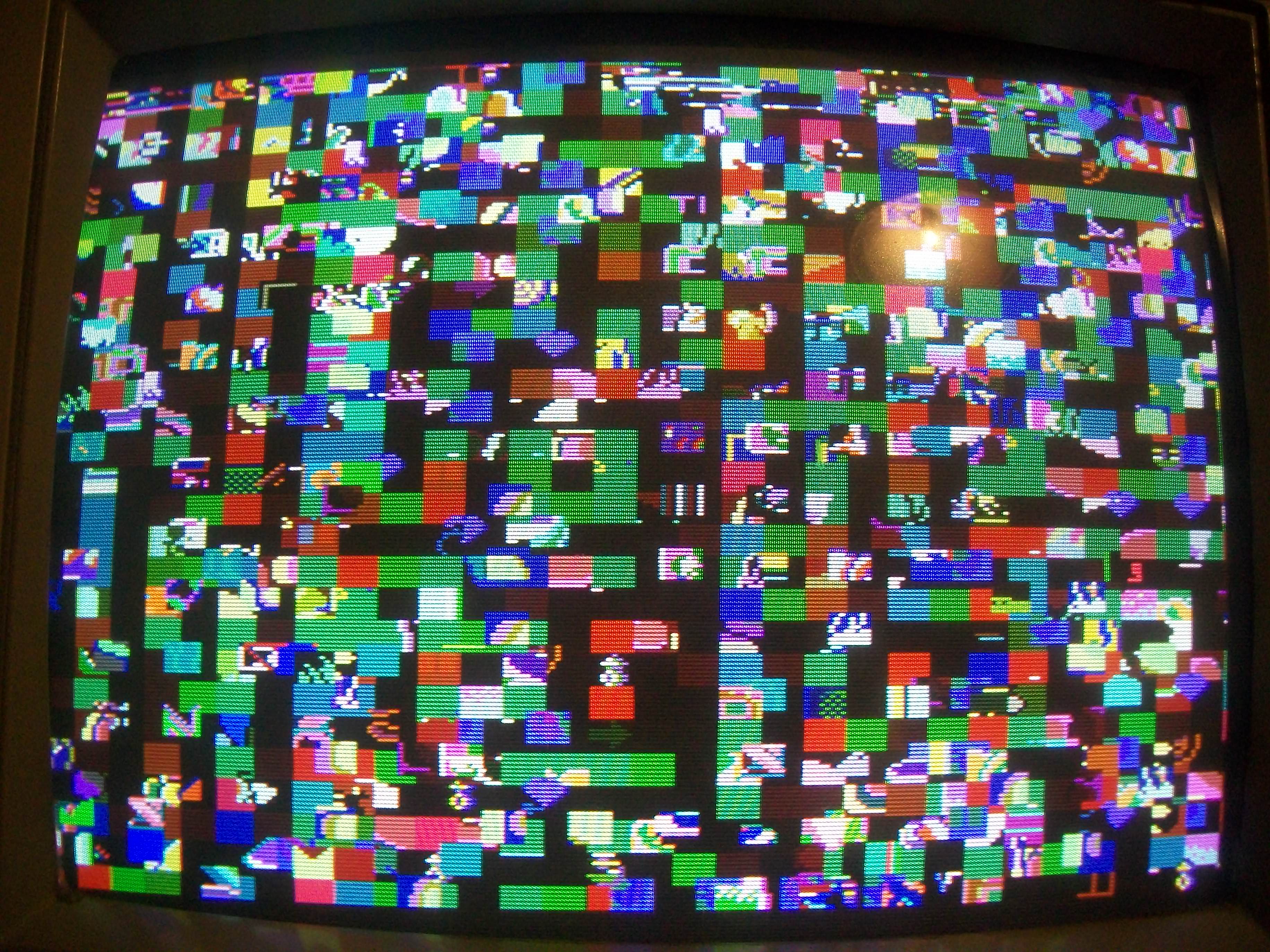
On boot I was greeted by this static garbage screen:

100_9078

Main Z80 CPU had /HALT line asserted and no activity on data bus.I dumped the program ROMs and they were good.So I thought this was a good chance to use my Fluke 901A troubleshooter.According to memory map in MAME source the WORK RAM  lies from 0xc000 to 0xcfff of the Z80 address space:

AM_RANGE(0xc000, 0xcfff) AM_RAM AM_SHARE("ram")

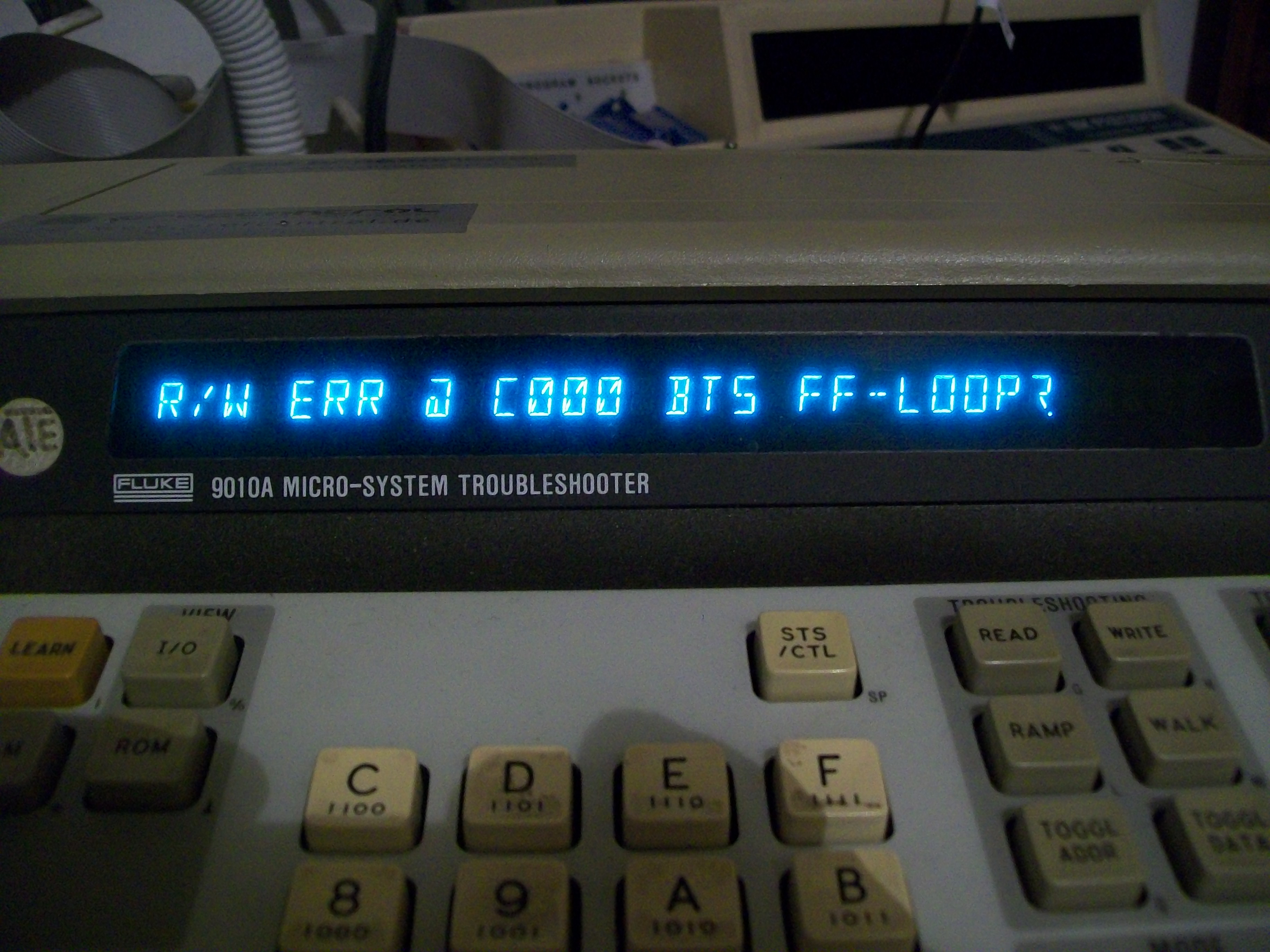
When I ran a long RAM test I got an R/W error at the beginning :

100_9082

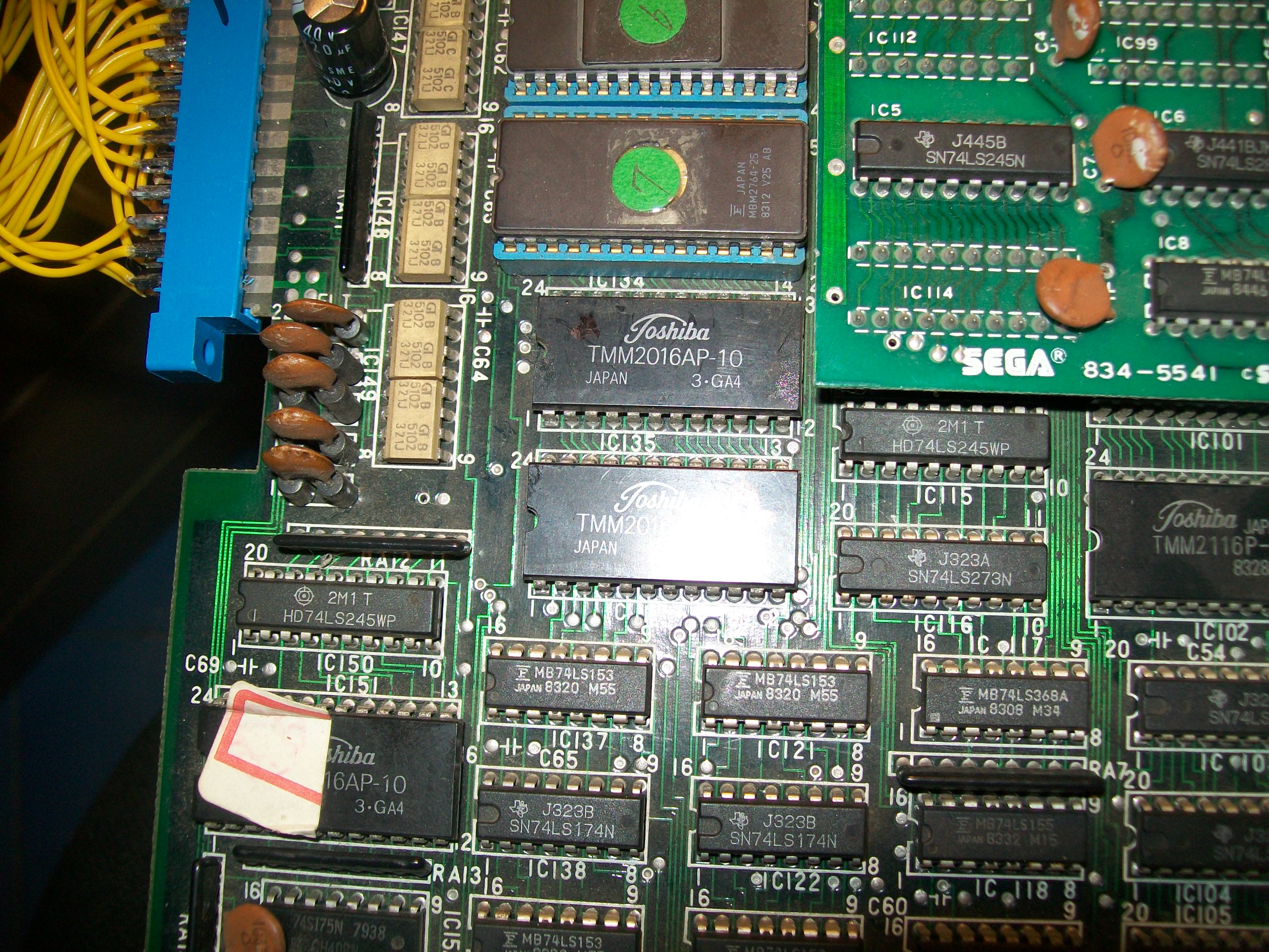
The WORK RAM is in form of two 2016 chips @IC135 and IC136 (so each one is 2K or 0x7ff in hex) :

100_9084

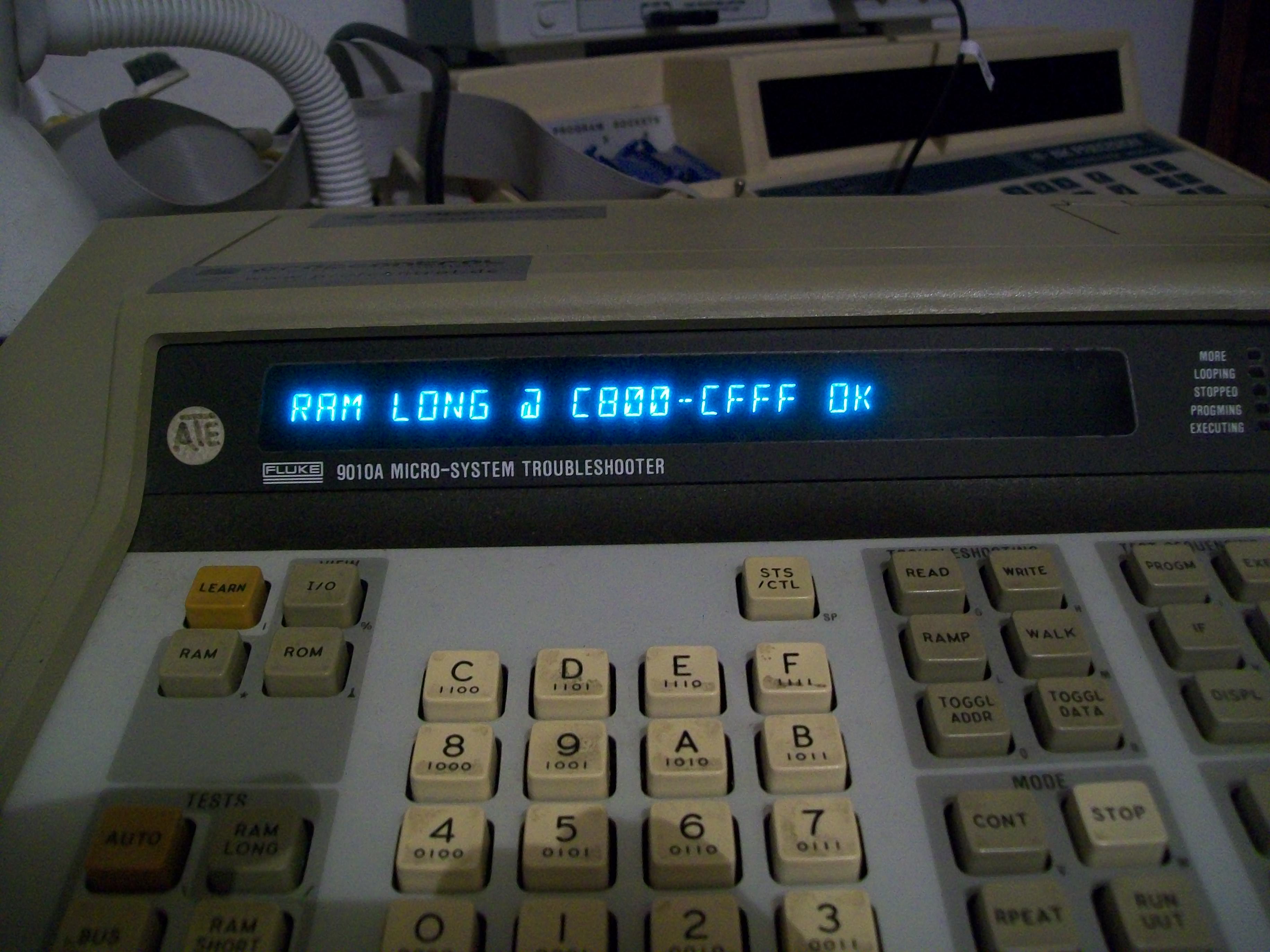
So I performed a test from 0xc800 to 0xcff which was successfully accomplished:

100_9081

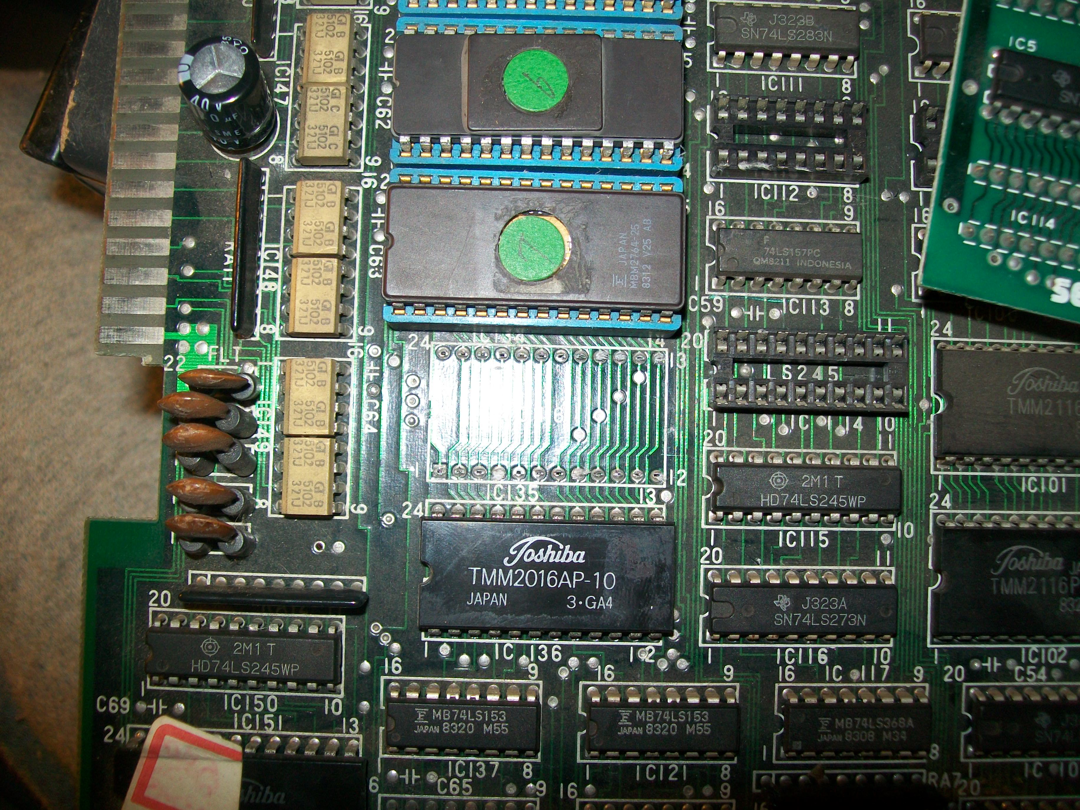
This meant the chip lying from 0xc000 to 0xc7ff had to be bad (the  74LS245 between the data bus of Z80 and RAMs were good since bus is shared among the two RAMs).I hooked up the Fluke probe and looping a write of some values I could identify which RAM chip lies in which address range.The one @IC135 lies from 0xc000 to 0xc7ff  while IC136 from 0xc800  to 0xcff.As further proof, I wrote random values in some memory locations from 0xc000 to 0xc7ff  and reading them back they didn’t match the written ones meaning the memory locations were faulty.So confident I removed the RAM @IC135:

100_9085

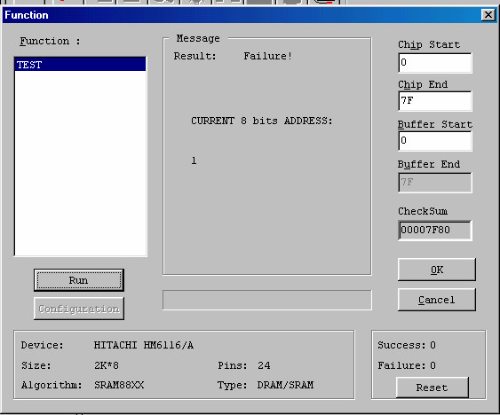
It failed miserably when tested out-of-circuit:

tmm2016ic135_failed

Fitted a socket and a good chip and board sprang to life with no issue.Another classic game preserved.

100_9086


 Posted by at 12:00 am

Aliens repair log #2

 PCB Repair Logs  Comments Off on Aliens repair log #2
Oct 092016
 

Got this Aliens PCB for a repair.Board was not in great shape, quite dirty :

100_9009

When I powered it up I was greeted from this screen repeating in an endless loop sign that board was watchdogging:

fullsizerender

The self-test reported two bad devices, in the case a 1Mbit MASK ROM @C24 contaning program code and a 2018 palette SRAM @E15 :

c24_e15_devices

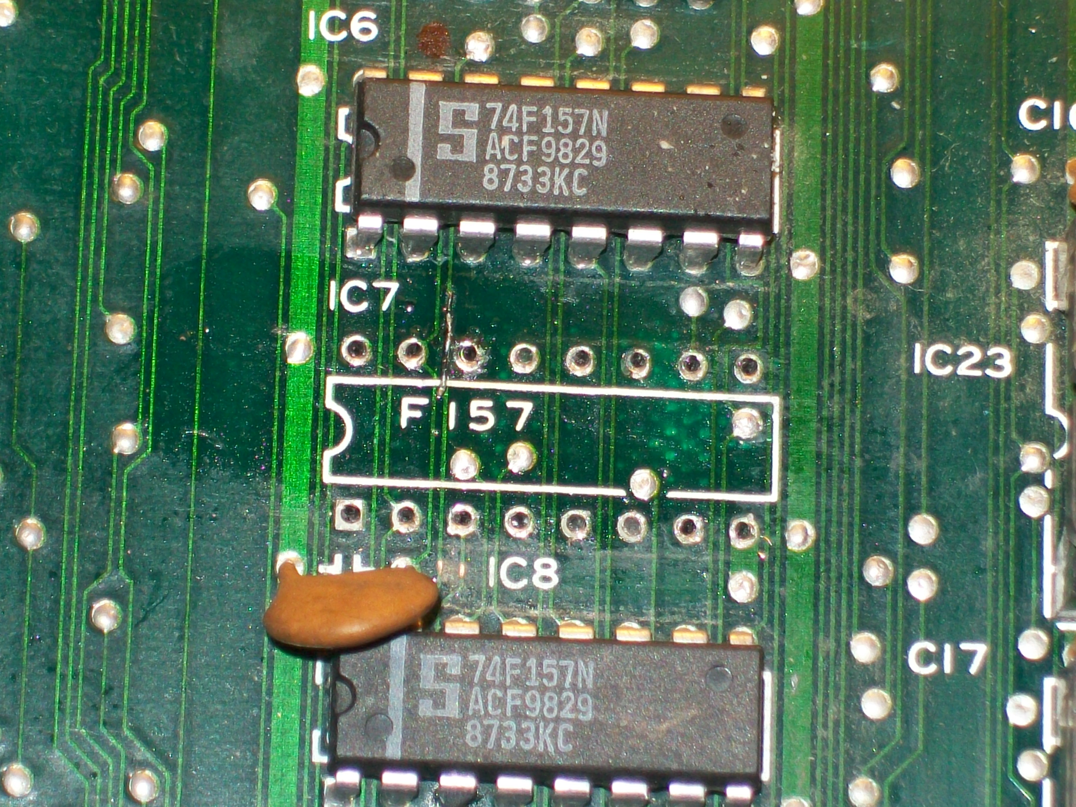
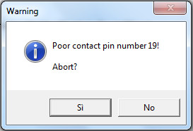
I dumped the MASK ROM and my programmer warned about a possible damage of the device:

insertion_error_romc24

I programmed an EPROM replacement and at same time replaced the palette SRAM @E15.The error @C24 was cleared but the SRAM was still reported as bad.Probing it revealed its PIN 21 (/OE) was stuck high.I could trace this signal back to pin 6 of a 74LS32 @E13, this was also confirmed by schematics (thanks again to ‘frsj8112’ for providing them)

oe_signal_e15_sram

I desoldered the 74LS32 and it failed when tested out-of-circuit (in gate n°2/pin 6, indeed):

74ls32e13

In this way I could succesfully pass the self-test and enter in game:

Some backgrounds and sprites were corrupted so I launched a MASK ROM check which reported bad devices:

mask_rom_check

Dumping them revealed they were really bad except for the ones @J2 and J8 which were good.I replaced them with 27C400 EPROMs.While I was doing my tests another RAM suddenly failed :

100_9037

I promptly replaced it:

100_9038

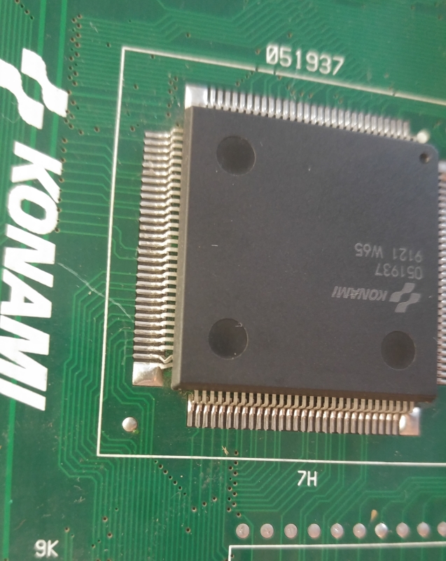
After reflowed the two custom ASIC sprites generator ‘051960’ and ‘051937’, MASK ROM check reported all devices as good:

100_9043

Backgrounds were perfect but some sprites were still garbled

Since the sprites MASK ROMs were all good and ruled out the two sprites custom generators as well as connections among them, I went to check the control lines of the MASK ROMs.When I probed the 74LS04 @F13 which generates the /OE signal for the devices @J2 and J8 :

j2_j8_oe__signal


my logic compator warned me about a trouble on pin 8:

100_9059

The problem was confimed by the scope (input pin 9 on the left, output pin 8 on the right of the below picture)

74sl04f13_analyzing

I removed the IC and it failed exactly in the pin 8 (the output of gate n°4)

74ls04_failedf13

Fitted a good IC and success!Board completely fixed!It was a long job but it was worth it to save this great classic.Ah, I forgot, obviously the two bad TTLs were from Fujitsu…


 Posted by at 11:12 pm

Raimais repair log

 PCB Repair Logs  Comments Off on Raimais repair log
Oct 052016
 

Got for a repair this Raimais PCB , an obscure maze game released by Taito in 1988 :

100_8907

Board played fine but sound was totally missing.If I put my fingers  on solderside of the amplifier I could hear some noises, sign that it was still good.Someone replaced invain the YM3016 DAC but this was not the cause.Ruled out a problem is the analog section, I went to check the digital circuitry.Sound CPU is a Z80 with a ROM and a RAM.When I went to check the RAM @IC25 (a Toshiba TMM2063, 6264 compatible,  almost prone to failure in my experience like Fujitsu TTLs) I found irregular activity on some data pins (on the left of the below picture an healthy signal) :

data_lines_comparison

I desoldered the chip:

100_8906

and tested it out-of-circuit where it failed (my programmer went in protection due a possible short , indeed I could measure few Ohms of resistance across VCC and GND pins of the chip)

tmm2063ic25

Fitted a good chip restored the sound.End of job.

 Posted by at 10:48 pm
Oct 052016
 

Received today this Fire Shark PCB for a repair:

100_8995

According to the owner, board would sit on a “OBJECT RAM ERROR”  but instead,  once powered up, the board entered in game but sprites were almost absent,spread on screen in form of lines and garbage:

Like many other Toplan games, also this one uses the ‘FCU-2’ custom ASIC sprites generator which , due its package, is the first thing to check if you have sprites issue:

100_8998

Visually I couldn’t see anything wrong with it but when I tested the soldering of each pin with a needle, I found some loose legs on a side :

100_8996

I promptly reflowed them and sprites were back properly formed:

100_9005_

The other issue reported by owner was that player 2 controls were not responding except for BUTTON#2, COIN and START.The screen of the TEST MODE clearly showed the stuck inputs:

img_7861

I traced these inputs back to a 4.7K Ohm resistor array used as pull-up and I found it was cracked in two:

100_9001

The scope confimed that half of pins were floating and not in high state like they should be :

bad_resistor_arrayra8

I removed the broken resistor array:

100_9002

and, after installed a good one, all the player 2 inputs were correctly working again.Board 100% fixed.

 Posted by at 9:14 pm