Jan 262017
 

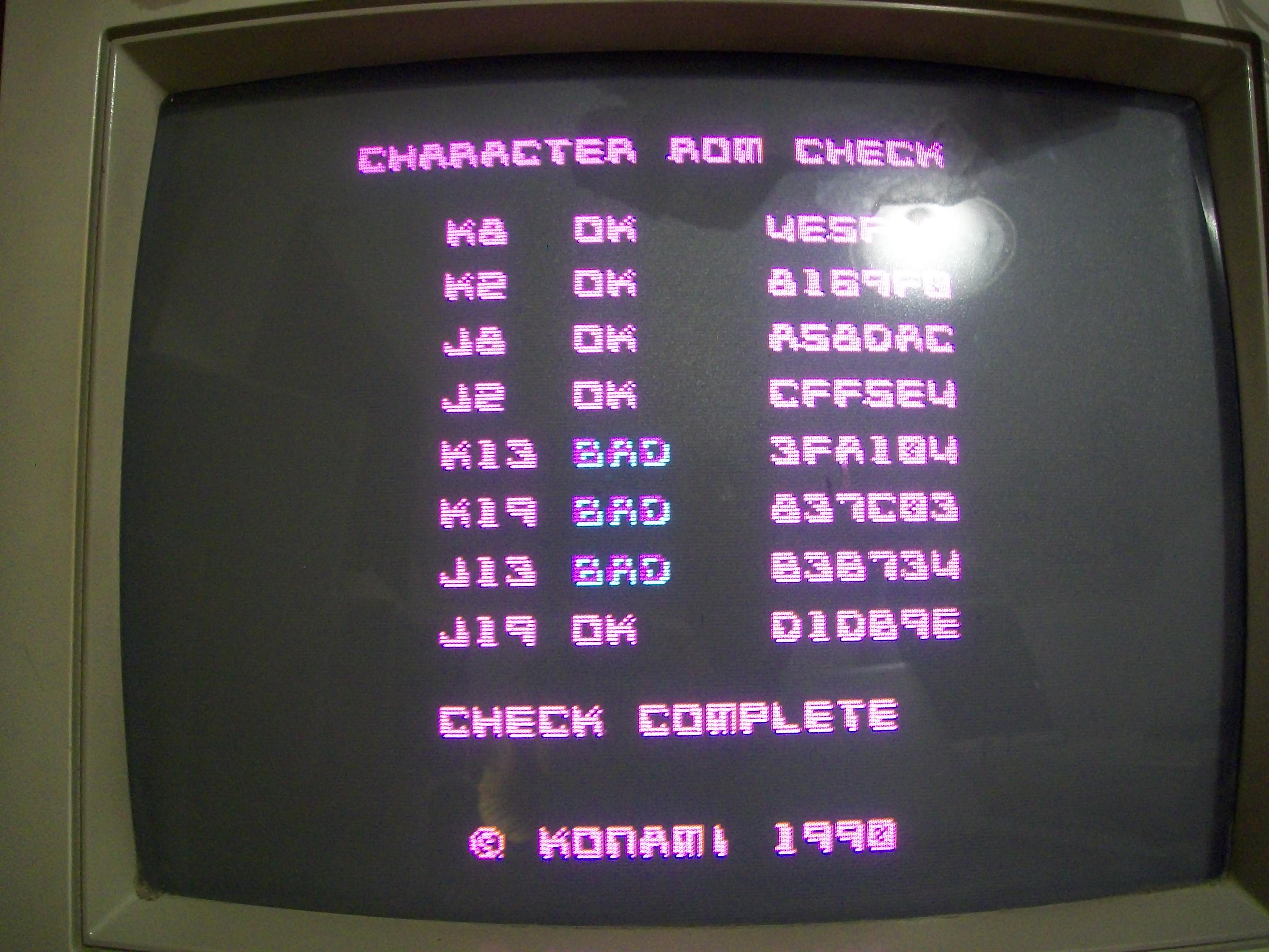
This is part two of my C64 repair which documents the replacement of the bad character generator rom using a standard 27c64 EPROM. My local electronics hobby store did not have anything else on hand; I was hoping for a 27c32 because that’s what most folks on the internet seem to be using to get this repair done. I didn’t want to wait, so I settled on the 27c64.

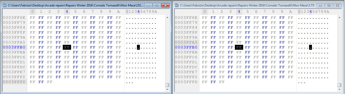
The first step was downloading a c64 character rom ( 901225-01 ) with a checksum of $F7F8 from the internet. There are plenty of sources for these.

After downloading the 4kb binary I ran the following command under Windows to fill up the entire 8kb of address space of the 27c64 ( upper and lower 4kb have the same data ). I couldn’t quite remember which half I needed to burn the contents to so this was a quick and fail safe solution.

copy /b 901225-01.bin+901225-01.bin 901225-01-doubled.bin

I take the 8kb binary ( 901225-01-doubled.bin ) and burn the image to my 27c64 EPROM.


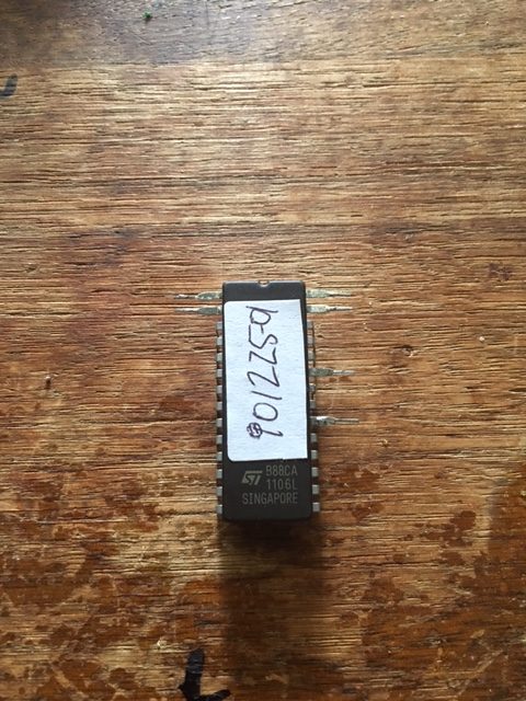
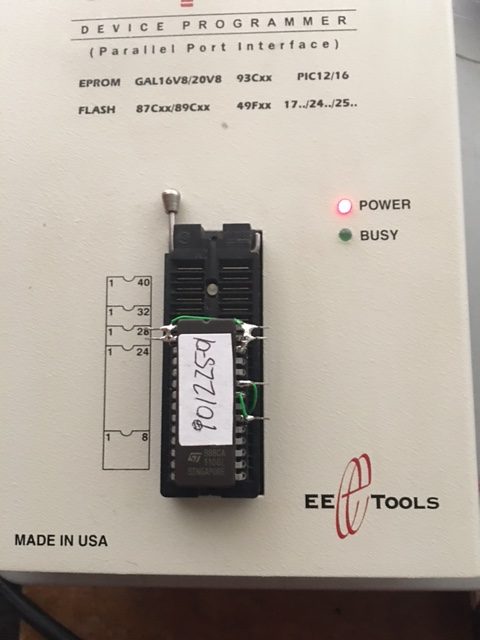
I bend the following pins outward on the 27c64 and cover the window with a sticker once the data is written.

1,2,20,23,27 & 28 ( bent out ).

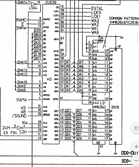
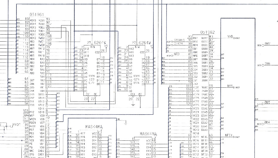
I made an adapter using a machined pin socket. This is the diagram I used to re-wire the chip which I found on this German site.

https://forum.classic-computing.de/index.php?page=Thread&threadID=4694


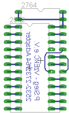
2532 pin 18 -> 27c64 pin 23 ( A11 )

2532 pin 21 -> is not connected ( VPP )

27c64 pin 20 -> 27c64 pin 22 ( /CE & /OE tied )

27c64 pin 1,2,26,27 & 28 ( VPP,A12,NC,/PGM & VCC all tied ).

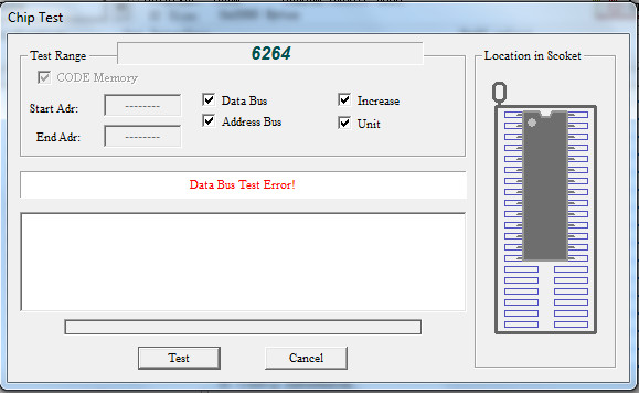
Once I finished wiring it was time to double check my work. I then select a 2532 device on Max Loader, load the original downloaded character generator rom into the buffer; this has a checksum of F7F8 which will be used for verification purposes.

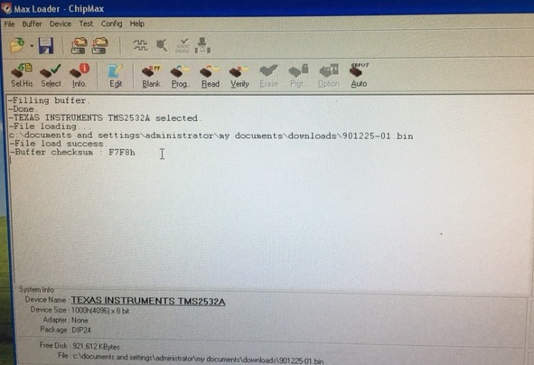
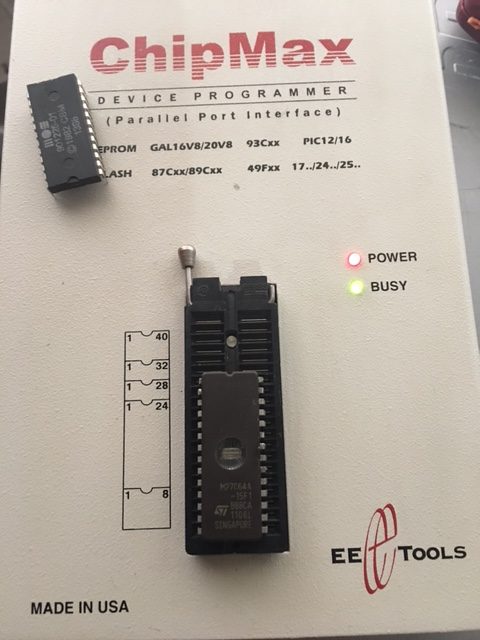
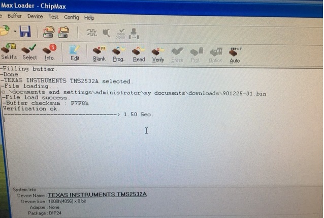
With the wiring complete I’m now ready to verify it’s contents. I will read the device as a 2532 EPROM and if all goes well it should report a checksum of F7F8

With the re-worked EPROM inserted into the ChipMax I hit verify. F7F8 was what I was after.

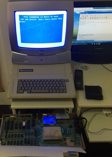
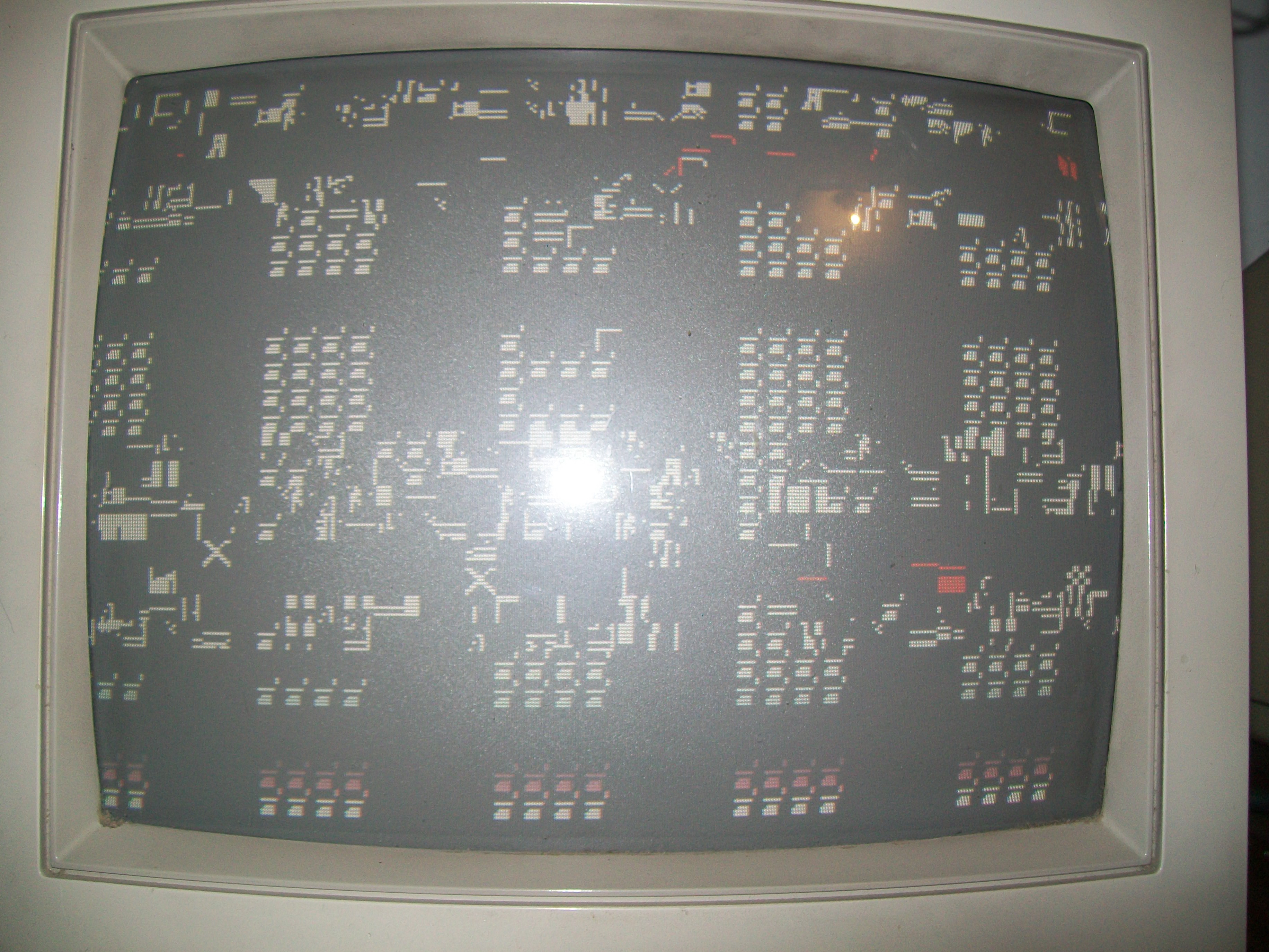
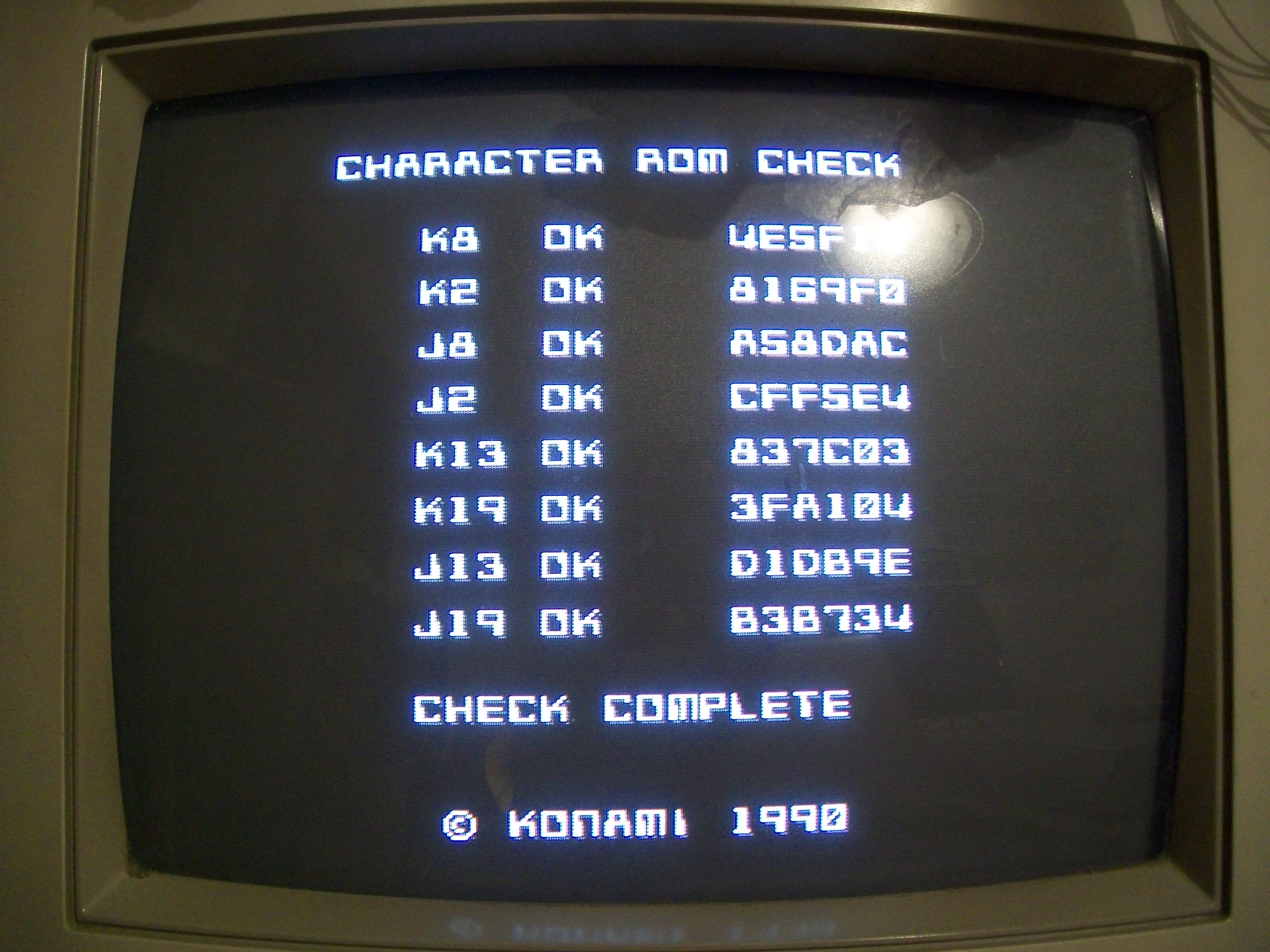
With that result I was so confident it was going to work that I trimmed the protruding pins and inserted the device into the C64 to produce the results I expected.

Vapor Trail – Hyper Offence Formation repair log #1

 PCB Repair Logs  Comments Off on Vapor Trail – Hyper Offence Formation repair log #1
Jan 192017
 

Sometimes it’s just matter of capacitors…We could call this repair log in this way, let’s read why.

I bought this not working  Vapor Trail – Hyper Offence Formation PCB on Ebay:

The board gave a static blank screen on power up:

Like other Data East games, hardware uses as main CPU a custom 68000 marked ’59’ :

Here you can see its pinout figured out by Porchy some time ago:

Data East ’59’ 68000 CPU Info

Probing it revealed static address/data bus, clock was present instead.Since it was not included in the above pinout I spent some time to figure out that pin 59 was the /RESET one.Probing it I found that on power up there was no transition from LOW to HIGH but pin went directly to HIGH state hence CPU didn’t get initialized.RESET circuit is a typical one made of the PST518 voltage monitor IC, a 47uF 50V electrolytic capacitor and a couple of resistors :

Checking in-circuit the ESR of this 47uF 50V capacitor @IC56 gave no reading, value was out of the 100Ohm range of my meter:

I removed it and out-of-circuit testing confirmed this capacitor was bad:

Replacing it restored a proper RESET signal so board successfully booted:

But sound was quiet despite adjusting the potentiometer and some interferences were present on screen too:

I went to measure the impedance of the electrolytic capacitors in analog sound circuit and I found many of them with out-of-specs value:

I replaced them all :

This restored a loud and a clear sound.As said in the beginning, it was only matter of capacitors!

 Posted by at 7:06 pm
Jan 092017
 

Received this Wild West C.O.W. Boys of Moo Mesa PCB for repair:

PCB was very dirty with flux residual and rust so I first washed it.After dried I powered it up and was greeted by this screen:

The initial self-test reported a bad ROM @T5 and a bad RAM @J4, obviously the board didn’t boot up but kept resetting.Usually Konami testing routines are very reliable so I went to dump the four program ROMs and actually the one @T5 showed at offset 0x3FFB4 a difference  of only one byte (well, one nibble..) compared to the MAME dump:

I reprogrammed the EPROM (a 27C020) and error was cleared but obviously the one regarding the RAM @J4 was still present:

RAM @J4 was one of the three RGB 2K x 8-bit palette RAMs :

Piggybacking it had not effect so, before removing the chip in order to test it out-of-circuit, I checked its connections with a multimeter.All was fine until  I could measure a short between pin 21 (/WE) of the RAM and VCC :

This explained why the RAM was reported as bad as it was never be written (write enable signal is active low).The /WE signals of the other two RAMs are generated by the near ‘054338’ custom :

so I went to inspect it with a digital microscope and found two bridged pins:

I removed the bridge and board successfully booted but sound was totally missing:

This is a common issue on these Konami board that use the ‘infamous’ hybrid audio module.This board has the ‘054986A’ one :

Usually you can fix this issue by replacing the capacitors but I opted for a drastic solution removing the module and installing two rounded machine-tooled strips with 1.778mm of pitch:

Lastly I used one of my ready module:

Job done.

 Posted by at 10:27 pm

Namco System 1 CPU board repair log #2

 PCB Repair Logs  Comments Off on Namco System 1 CPU board repair log #2
Jan 072017
 

Another Namco System 1 CPU board on the bench after the past one :

Board (coupled with a good ROM board) gave only a black screen with some green lines, watchdog was active :

I checked the three colors outputs and only the green was active, the other two were dead:

We saw in the past repair that there are three 6264 static RAMs, each one for a color, they are addressed by the custom ‘C120’ and data are processed by the custom ‘C116’  which generates the different shades (then formed into a single color and converted to analog signals from some resistor arrays)

Probing the RAMs revealed stuck signals on data pins of the ones @B2 (RED related) and E2 (BLUE).I removed them :

But during desoldering I decided to remove also the GREEN one @D2.They all failed when tested out-of-circuit:

But also with good RAMs I got no improvement, watchdog was no longer active but all three colors still dead.Probing the other RAMs on board, I found no data coming out the two 6264 @D6 and E6 despite address lines were active:

When tested both out-of-circuit actually only the one @E6 failed:

Finally the board booted but with missing sprites and music (ony FXs were present).Here’s a video using a World Stadium ’89 ROM board:

I noticed that if I piggybacked the 6264 RAM @L3 ( used by the custom ’30’ which controls the sound), the rustling sound I had instead of the music disappeared:

So I removed the RAM and it failed the test:

This restored full sound.Now the sprites issue.I noticed that, when using this CPU board with a Galaga88 ROM board, the sprites (that were competely missing when using the World Stadium ’89 one) were visible but garbled and blocky:

The two customs related to objects (the sprites address generator ’48’ and the sprites generator ’39’ ) were good but probing the two 74LS377 @A3 and A4 revealed stuck outputs:

I promptly removed them and they both failed when tested out-of-circuit:

Replacing them restored the sprites and fixed completely the board.Five RAMs and two TTL replaced to achieve this, a nice booty…

 Posted by at 10:43 am

Aliens repair log #3

 PCB Repair Logs  Comments Off on Aliens repair log #3
Jan 042017
 

Received this faulty Konami Aliens PCB for repair :

Board was in poor condition, dirty, custom ASICs were full of flux residual, four GFX 4Mbit MASK ROMs were removed and socketed most likey using improperly an heat gun judging from bubbles on solderside of the PCB:

For first I washed the board.Once dried, I powered it up and I was greeted by this repeating screen :

This should be the self-test report but graphics was all messed up sign that there was some problem in the tiles generation (the red characthers most likey referred to some RAMs reported as bad).Therefore I went to inspected the reworked area on solderside and found that a couple of rivets were ripped off during the desoldering operation, these should have tied to VCC since they were pin 31 (/BYTE) of two 4Mbit MASK ROMs

I checked all the connections on the reworked area against schematics :

I found some poor contact between the two tile generators ‘052109’ –  ‘051962’ and MASK ROMs/ RAMs

This allowed the board to succesfully boot but some tiles had bad colors:

MASK ROMs test reported three bad devices:

Since they were socketed I dumped them and compared against MAME.They resulted good but I realized they were put in wrong sockets!I swapped them and MASK ROM test succesfully passed :

No other issue was found so also this board was declared as 100% working.

 Posted by at 4:43 pm