Tatsujin Oh repair log #1

 PCB Repair Logs  Comments Off on Tatsujin Oh repair log #1
Mar 182017
 

Some months ago I received for a repair this Tatsujin Oh PCB (known outside Japan as Truxton II)

As you can see from the above picture, the custom ‘HK-1000’ (used for inputs) in front of JAMMA edge was missing but this was not the main problem, board won’t sync up:

All the graphics and video timing signal (HSYNC, VSYNC, etc..) are generated by a large surface mounted ASIC (208 pins QFP package) marked ‘GP9001’:

You can find its pinout on page 32 of the Knuckle Bash schematics:

https://www.jammarcade.net/files/Schematics/Arcade/Knuckle%20Bash.pdf

The IC was previously reworked by someone in a bad way, many pins were bridged together, flux residuals were not cleaned.So I decided to remove it :

and solder it again:

Happy with the result I powered up the board again and I was greeted but this static garbage screen:

Probing the main 68000 CPU revealed no activity on data bus.Doing a visual inspection of PCB I found a couple of severed traces on solderside just around the CPU area:

Patching them allowed the board to boot but, obviously, due the lack of the ‘HK-1000’, the game was stuck on a ‘TILT’ error message:

Input check in TEST mode reported ON most of them  :

Now some words on the ‘HK-1000’.As said, this custom handles all inputs and it’s has been adopted in later Toaplan PCBs.There are two revisions of it, the early one has a ceramic package and due this nature it’s very prone to damage and failure.This revision is used on Truxton II/Tatsujin Oh and FixEight:

The newer revision is more robust and it’s used on Ghox, Pipi & Bibis:

Back to repair, from available info it seems the functions of this custom can be reproduced using a couple of 74LS240  (actually the custom handles also the coin counters and lockout but we can omit it), this is not a suprise for me since a lot of previous Toaplan boards use same design with these TTLs (see for example Truxton, Wardner, Hellfire and other).Doing some tests with a single 74LS240 I was able to successfully map some inputs turning off the TILT error

This allowed me to enter in game :

Later, owner of the board installed the missing HK-1000 and confirmed the board was perfectly working after my repair:

P.S.

I’m currently drawing schematics for the replacement of the HK-1000 and I will post here my results.Stay tuned.

 Posted by at 11:12 pm

Truxton repair log #2

 PCB Repair Logs  Comments Off on Truxton repair log #2
Mar 182017
 

Some days ago I had this Truxton PCB on the bench:

Game had wrong colors on some background/foreground objects, like title screen

This part of graphics is generated by a ceramic PGA custom marked ‘NEC D65081R’ which addresses four 1Mbit MASK ROM and read/write data from/to four 62256 static RAMs:

Address bus is daisy-chained between the custom, the four MASK ROMs and the four RAMs, all was in order here.Custom receives data from MASK ROMs and transmits/receives to/from from RAMs on two different bus.When I went to check connections, I found no continuity between pin 17 (D5) of the RAM @18F and the custom.Here is where trace from pin of the RAM goes under the custom (picture taken with a USB microscope)

Infact, if I pressed the custom in this corner, the fault went away.I simply reflowed this dry joint and all came back to normality.

 Posted by at 6:44 pm
Mar 162017
 

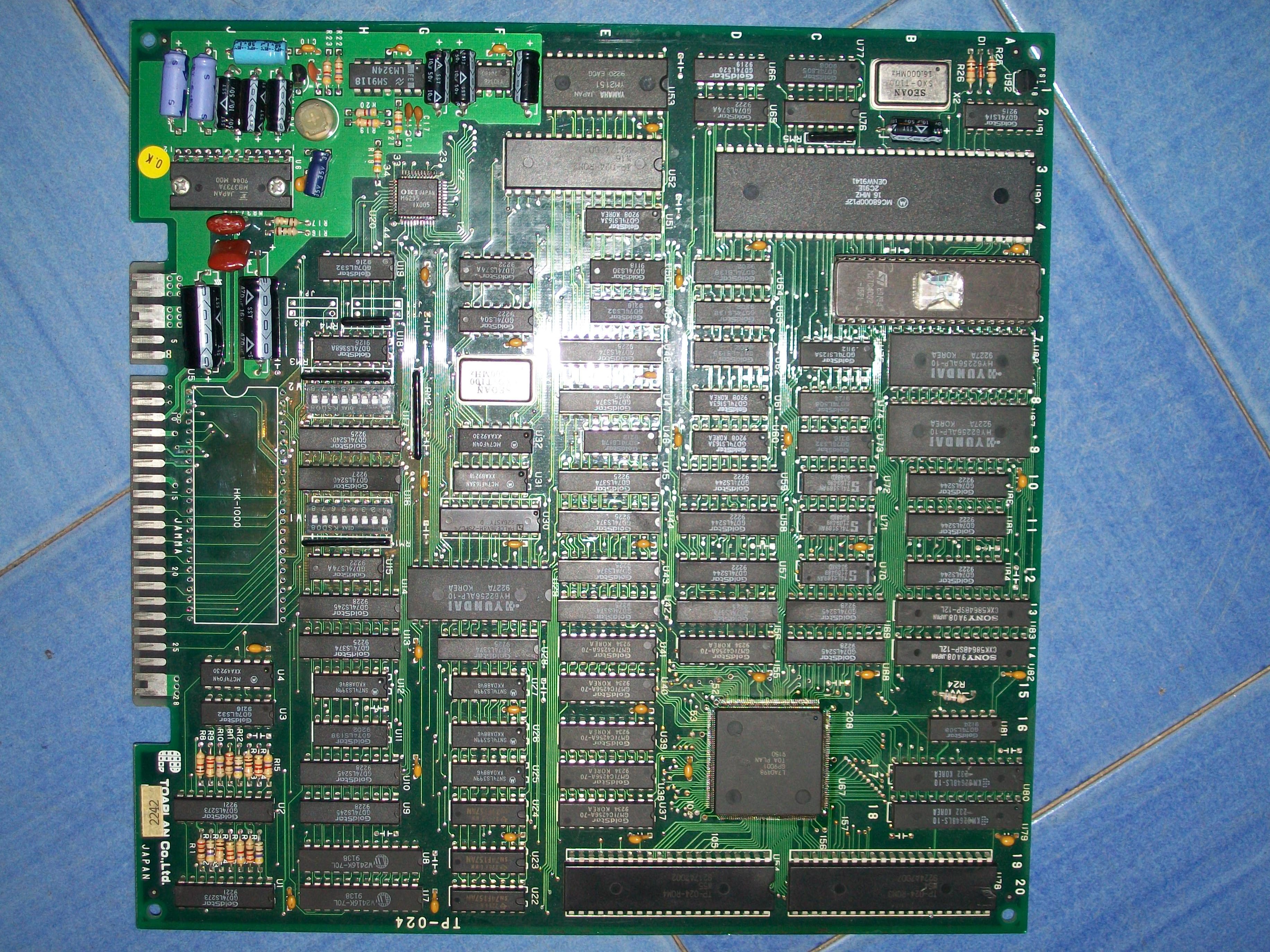
I bought this game for my collection declared perfectly working.

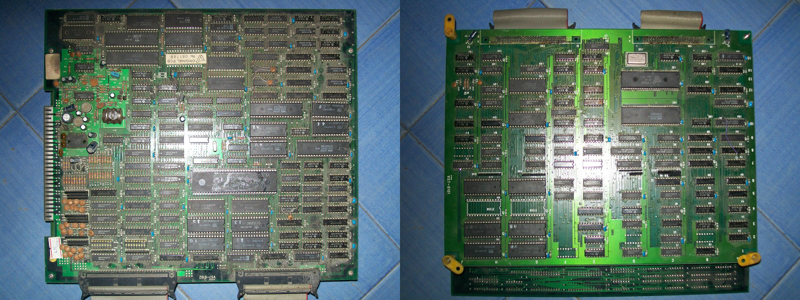
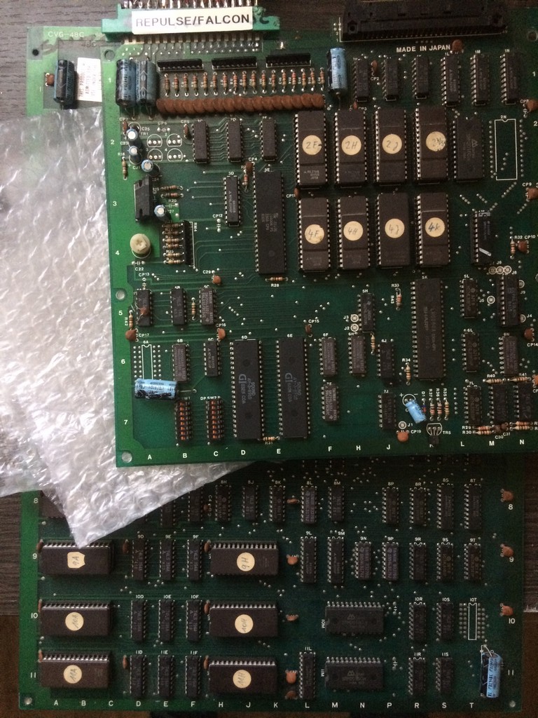
Flashgal runs on the very same pcb of other two games developed by Kyugo which are 99 Last War and Legend.

On the bottom pcb it is silkscreened CVG-48C which is very similar to the codes used by ORCA on their hardware


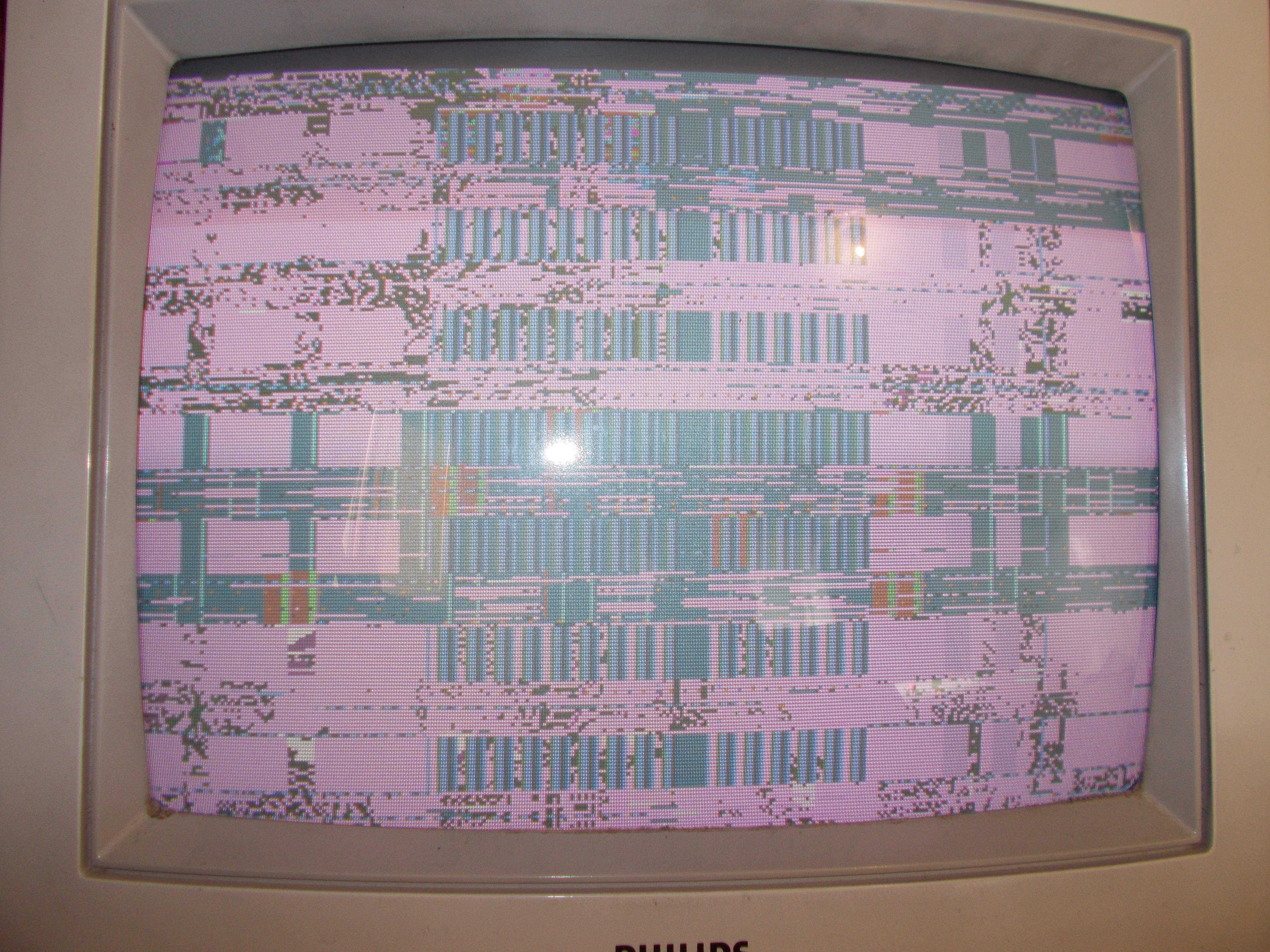
Anyway  it seems that in these days I am very unlucky because the game once fired up had a sync problem


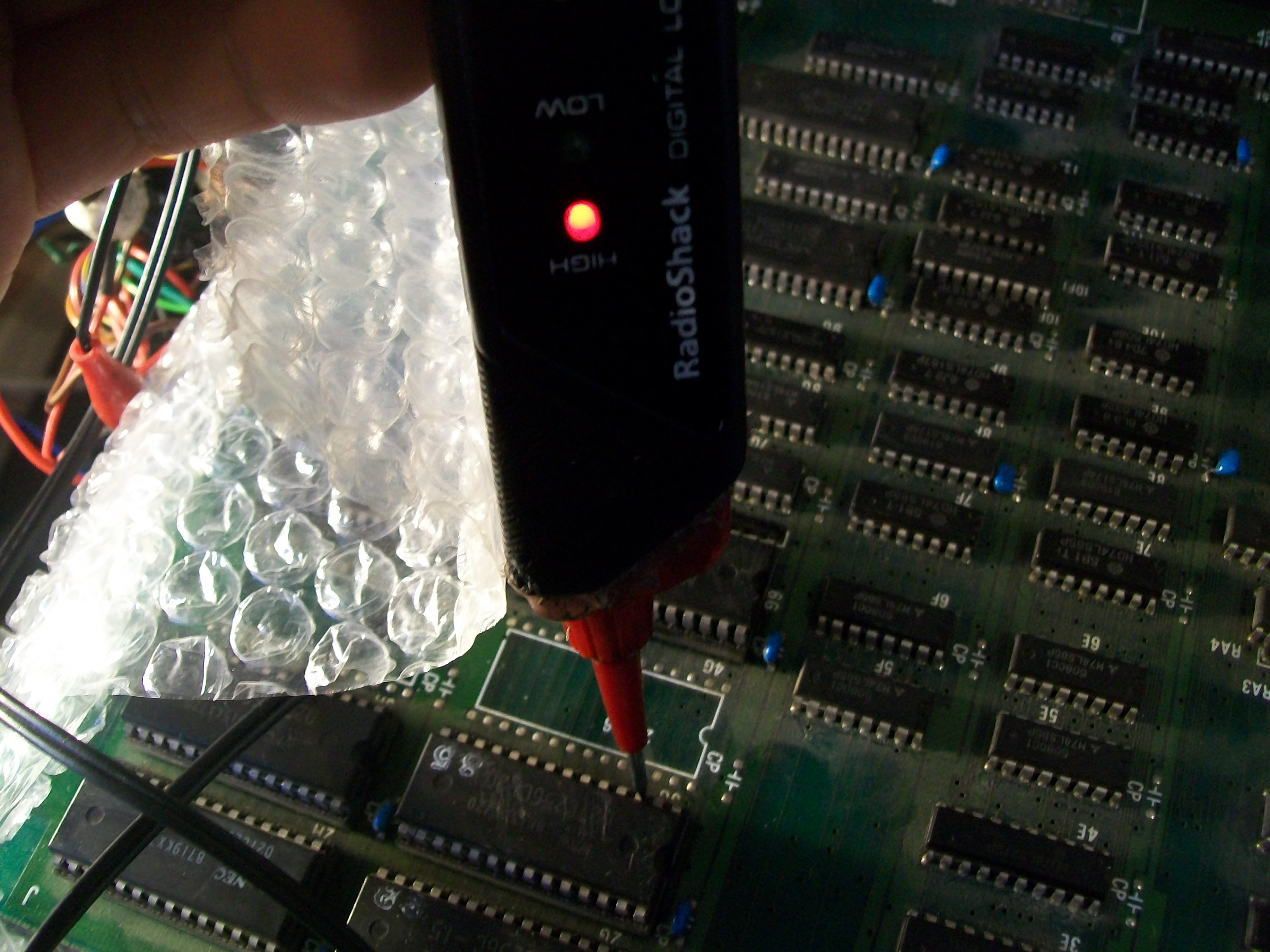
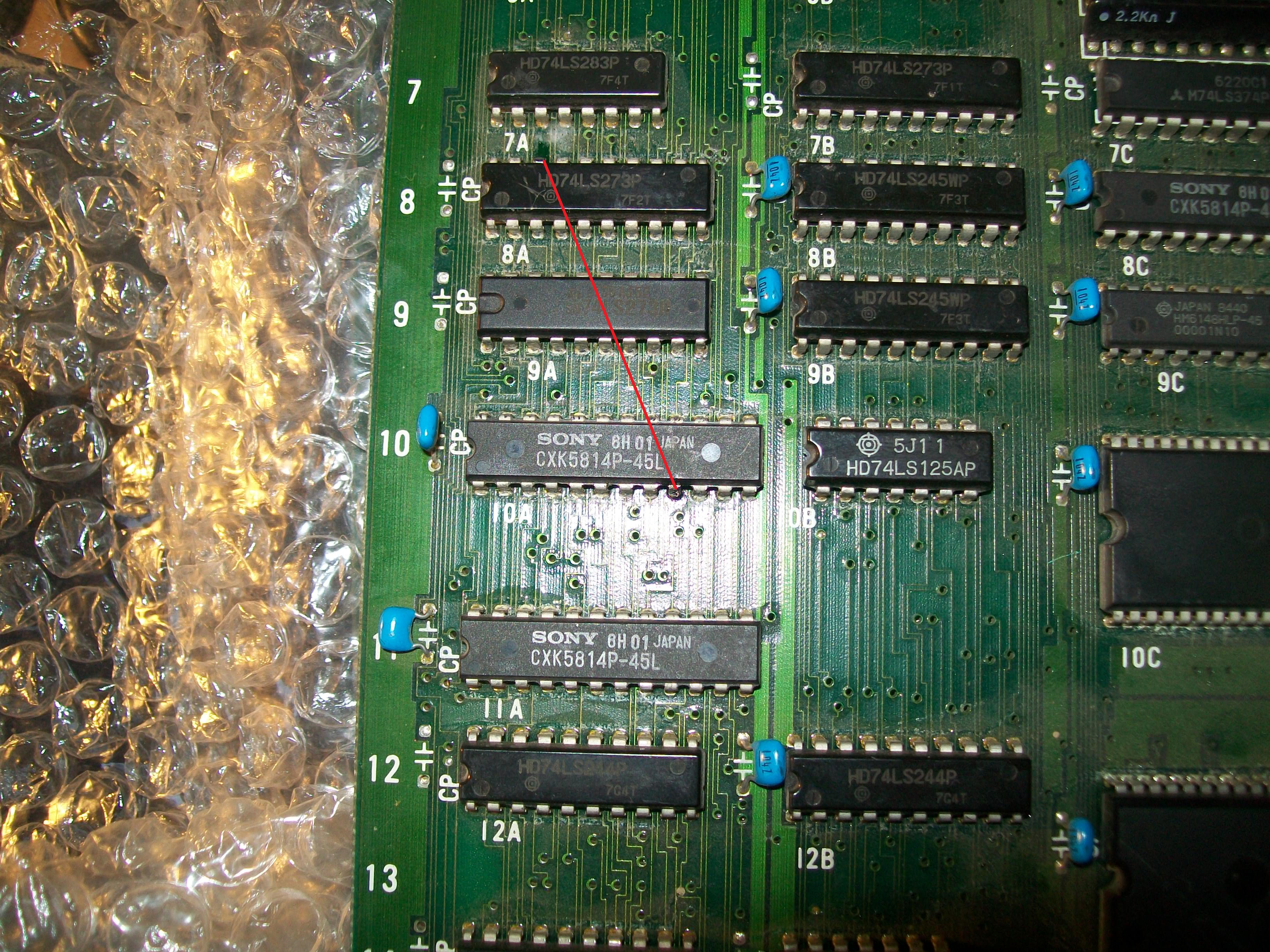
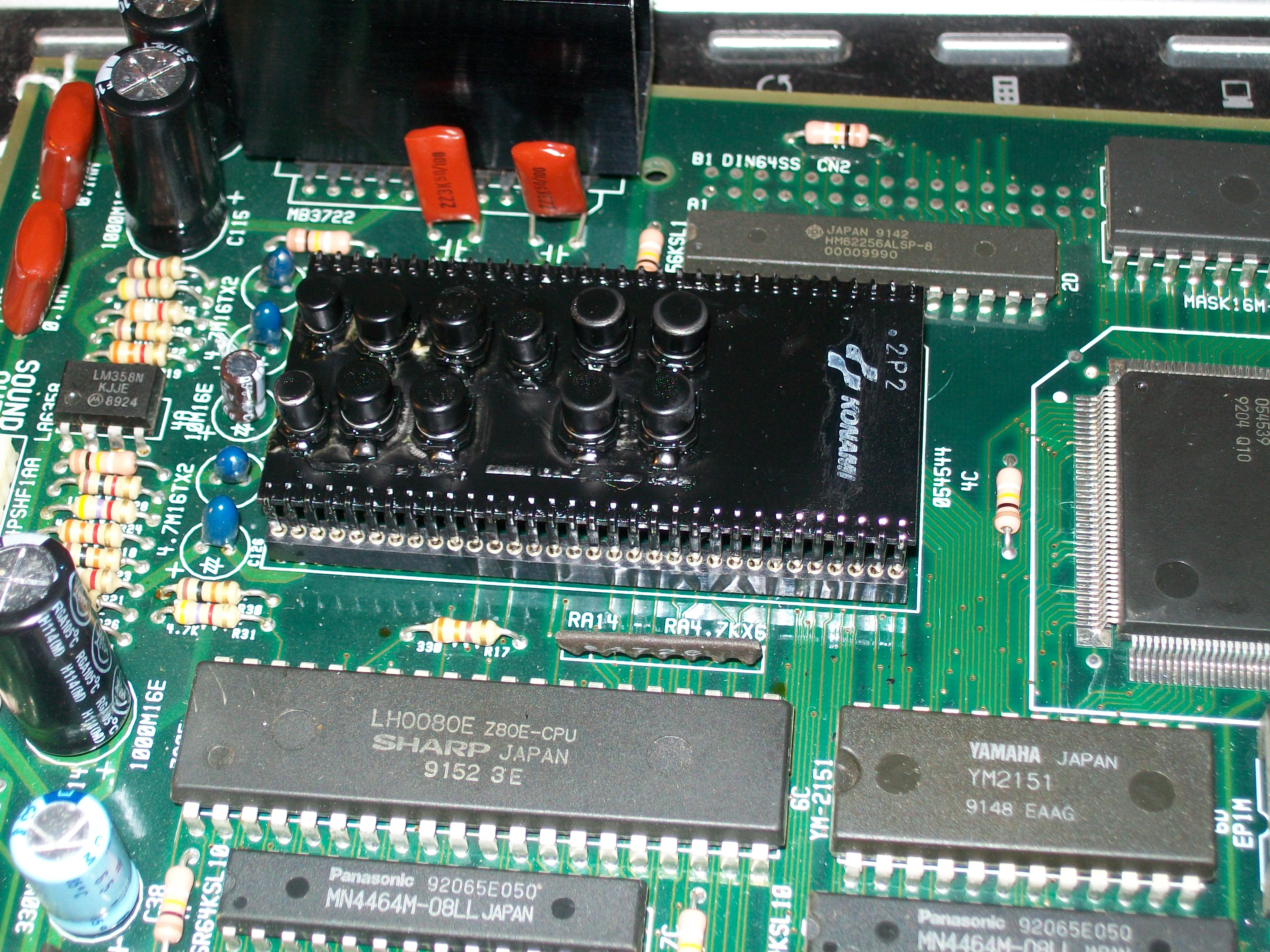
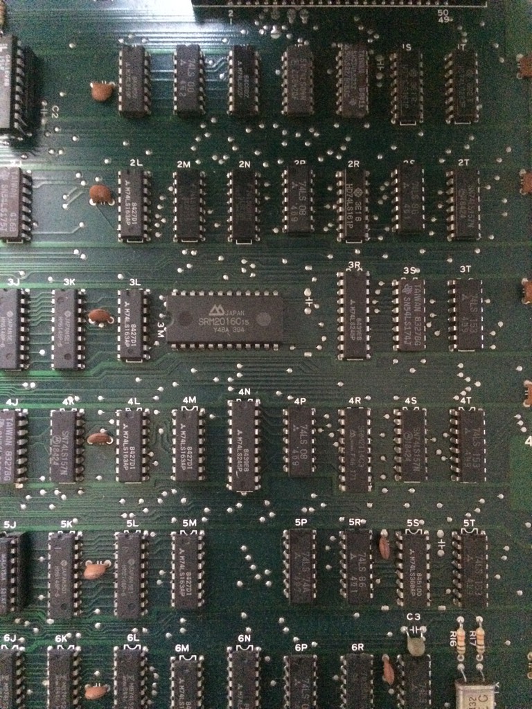
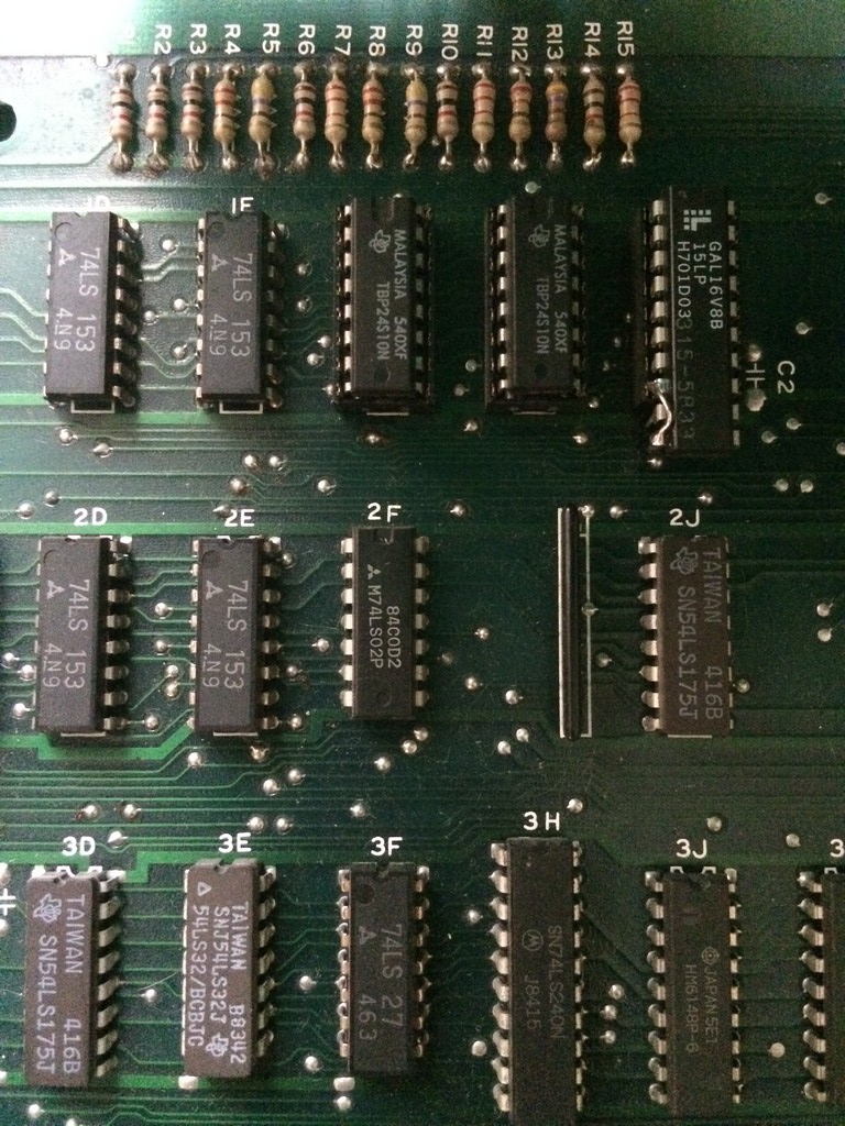
Tracing back from the SYNC pin I came to a 74LS08@2P

With the frequency counter I got very unstable readings so I proceeded to piggyback it with a good 74LS08 which restored the sync.

After changing it, it tested good out of circuit, yet with the new TTL in place I got a stable sync….

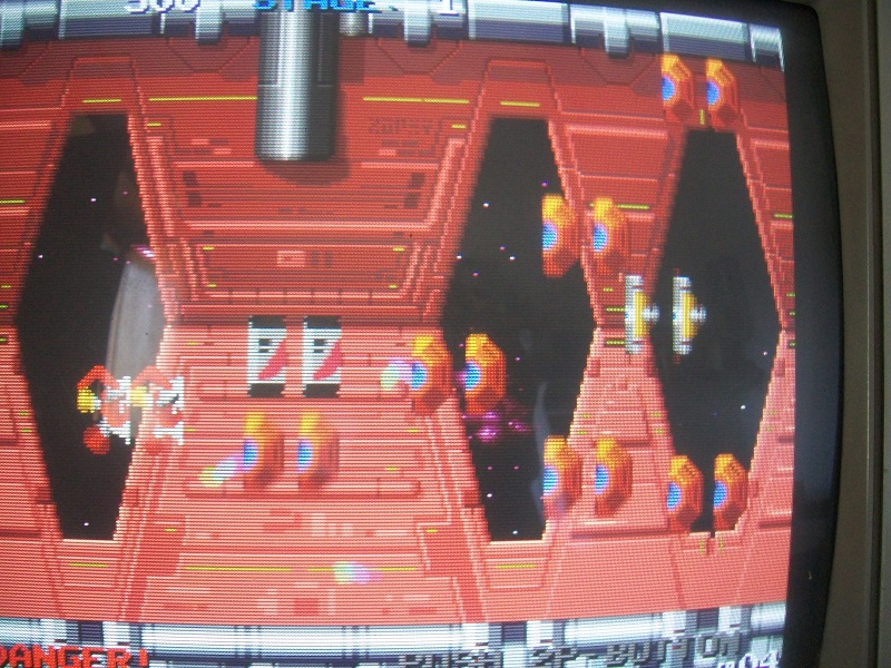
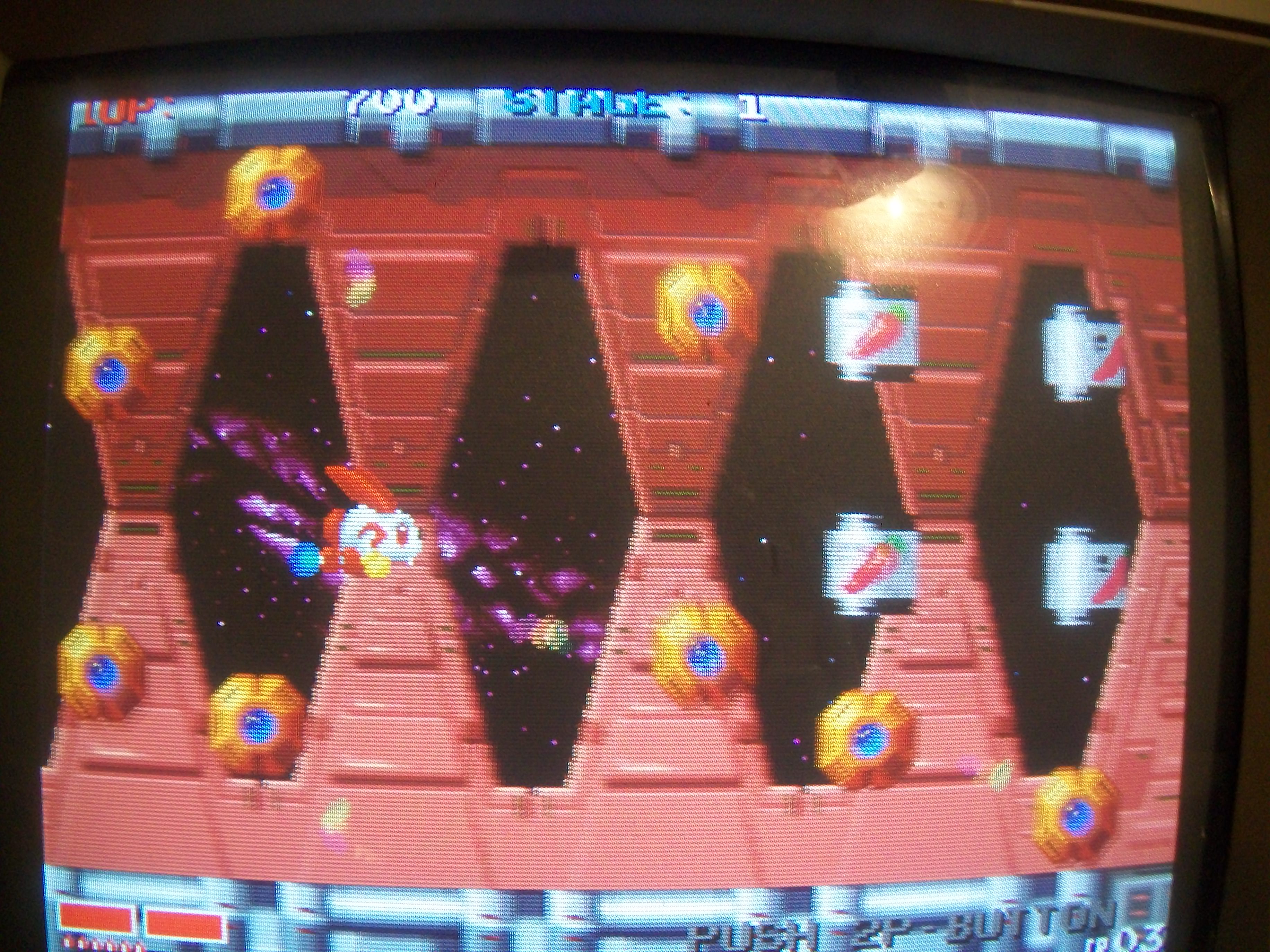
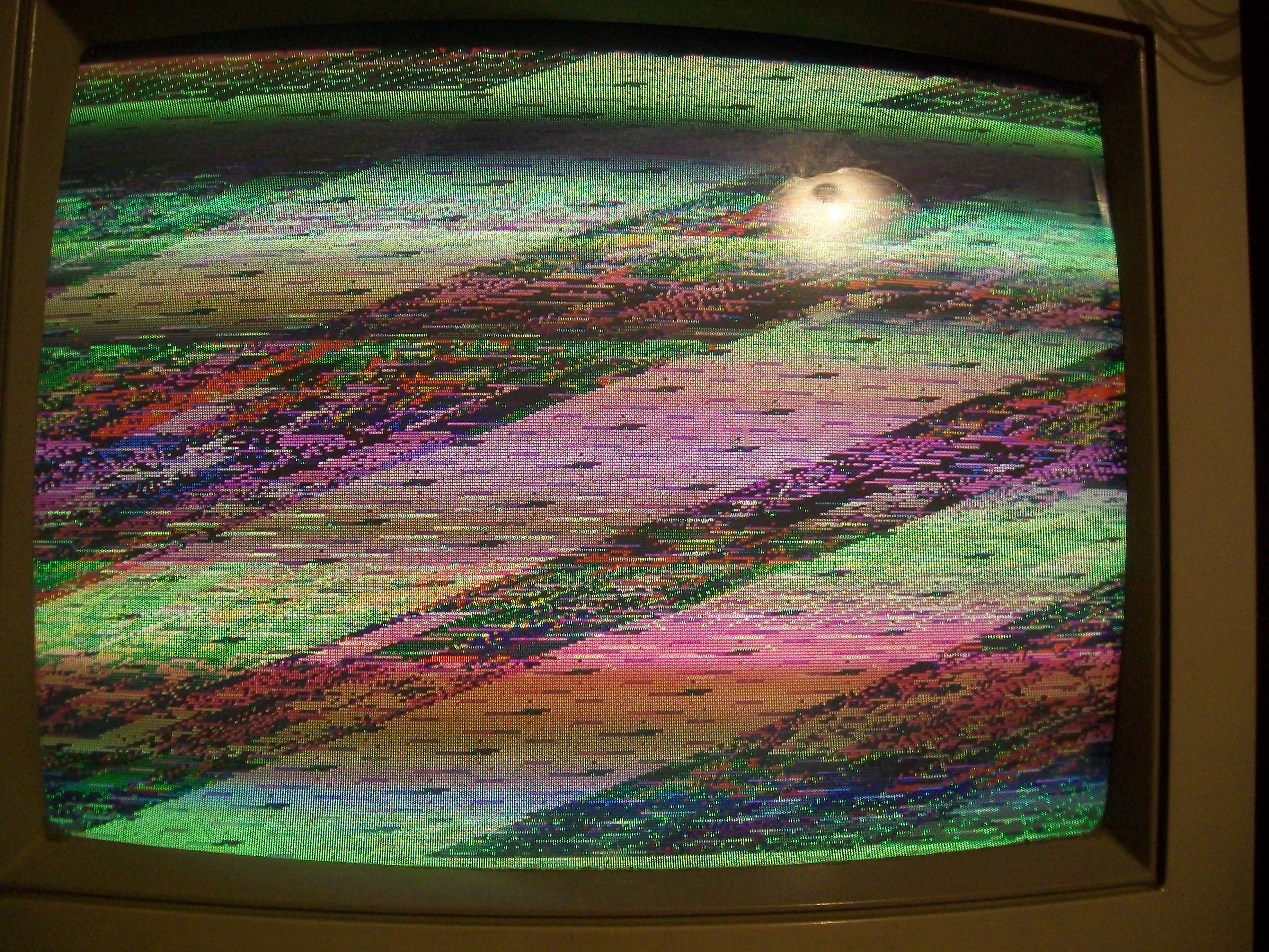
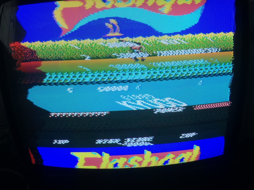
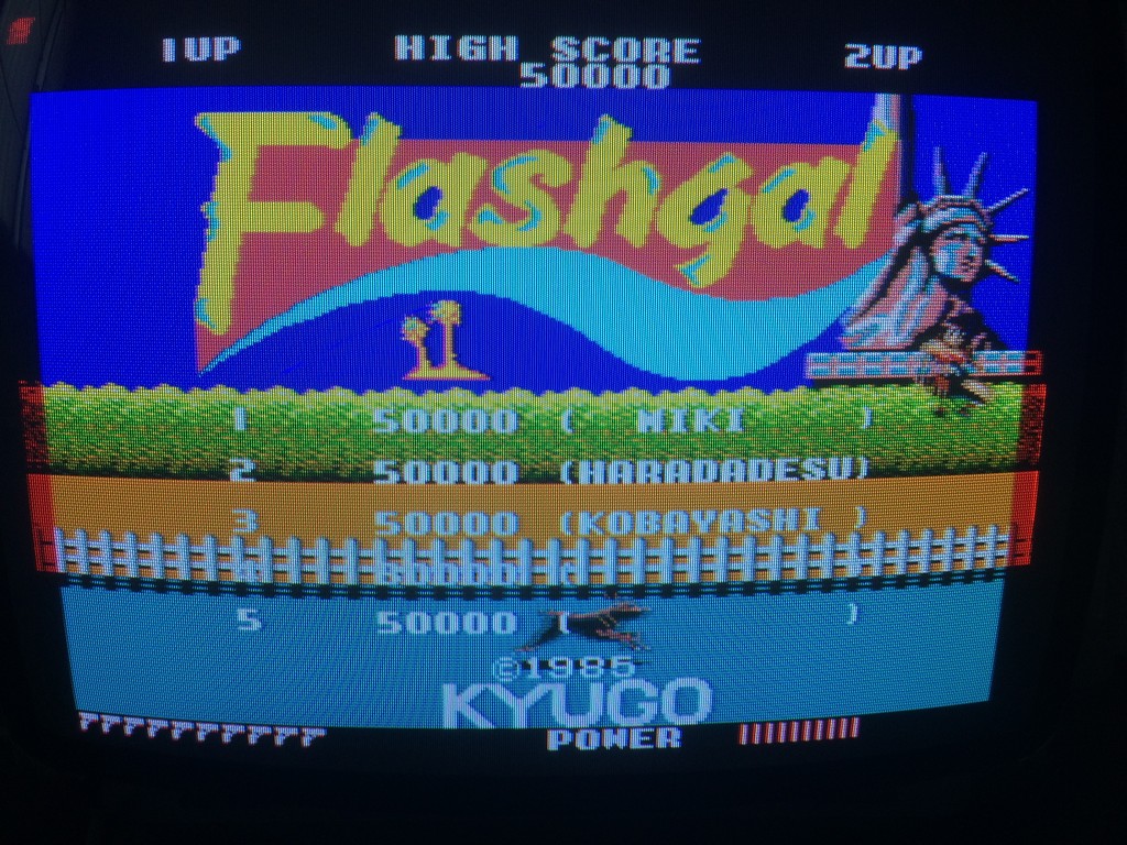
The screen looked very reddish so there was obiviously a palette problem

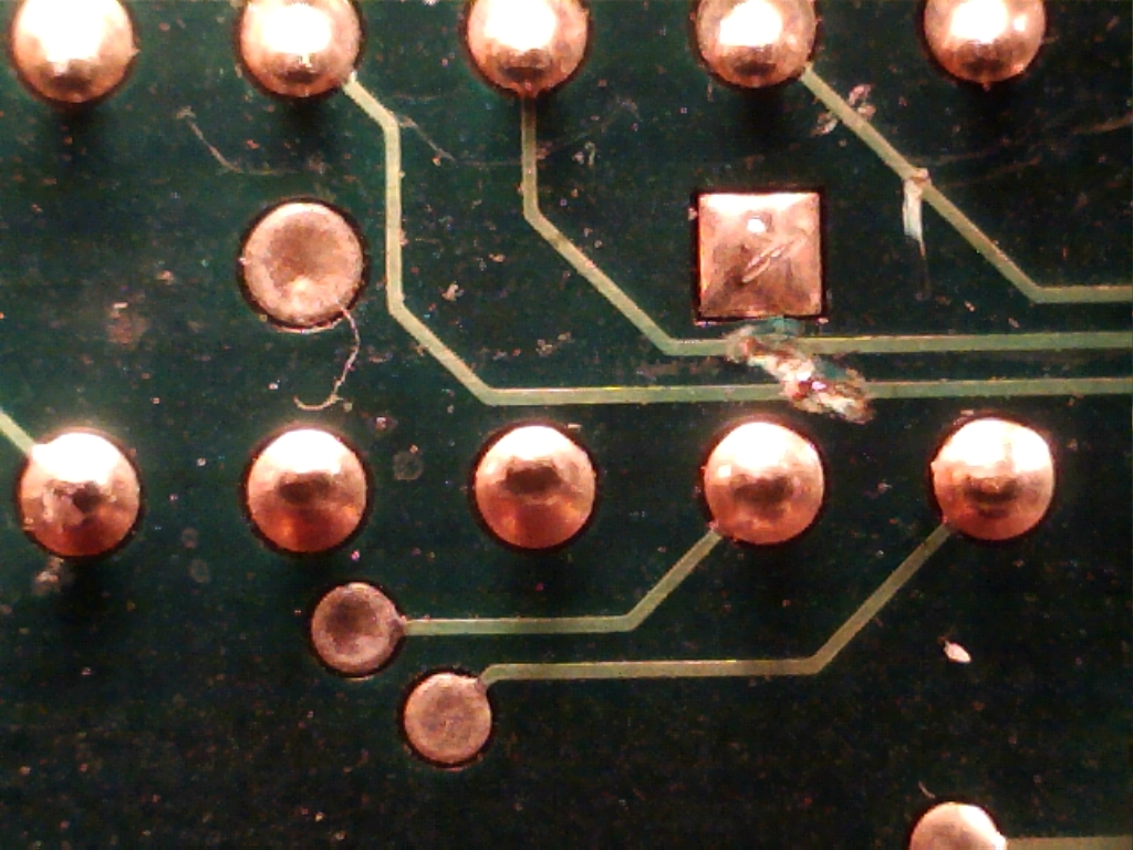
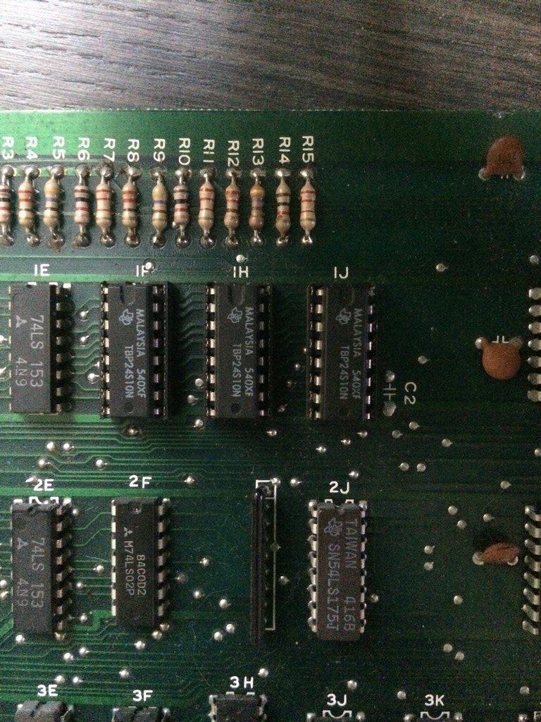
I checked the palette rams and they were all good so I dumped the colour proms until I found the RED component one @1J which didn’t match anything in MAME.

The prom is an 82s129 and it is almost impossible to find an empty replacement these days.

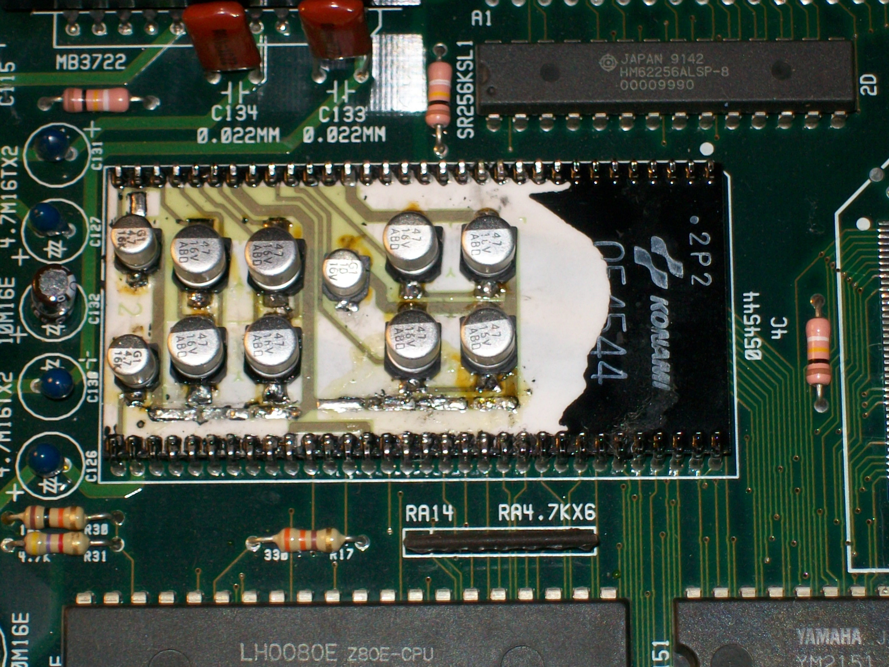
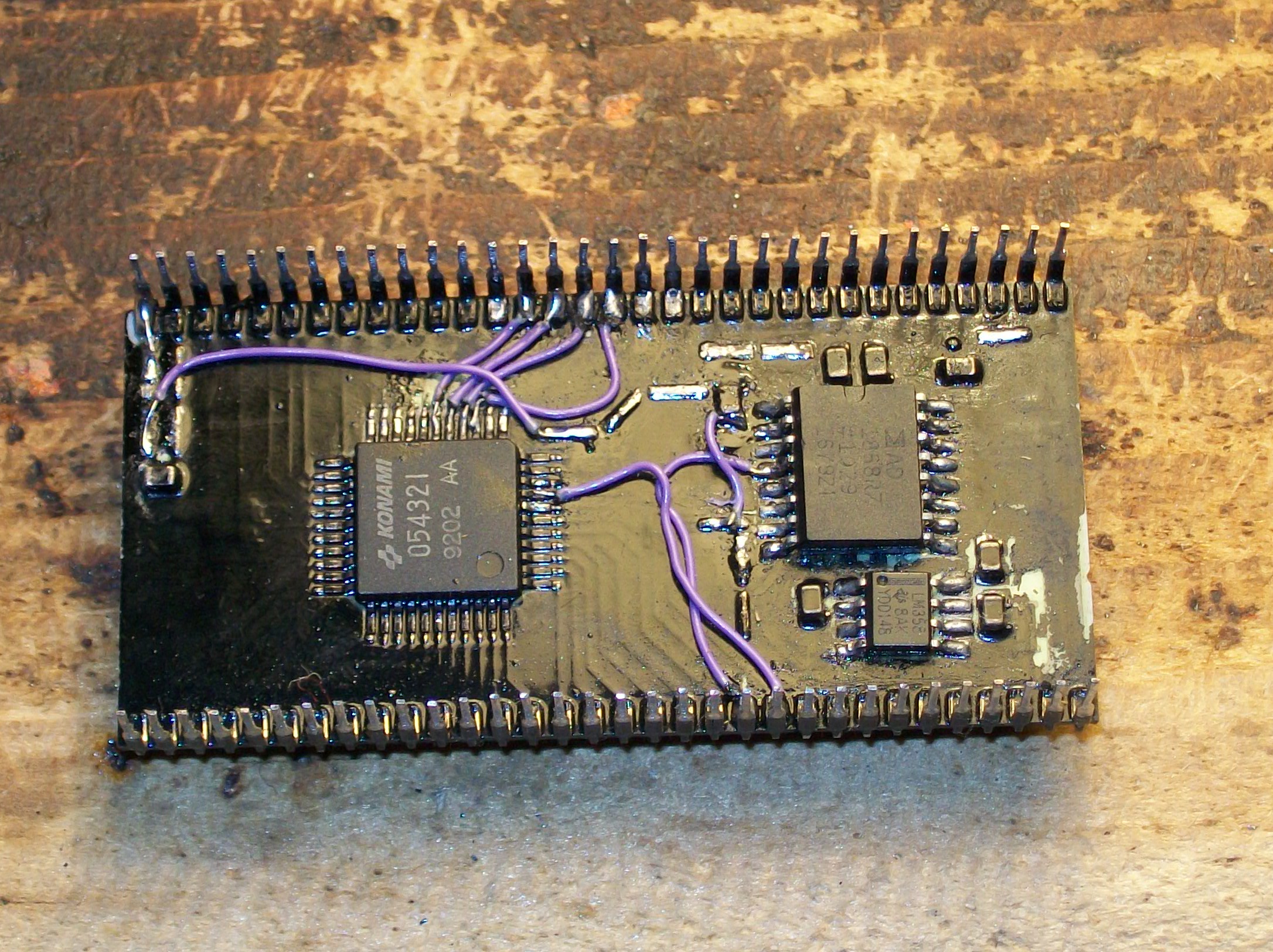
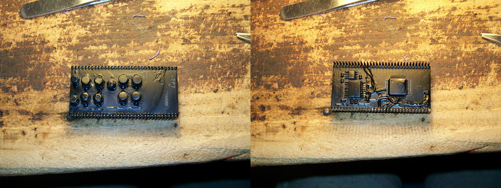
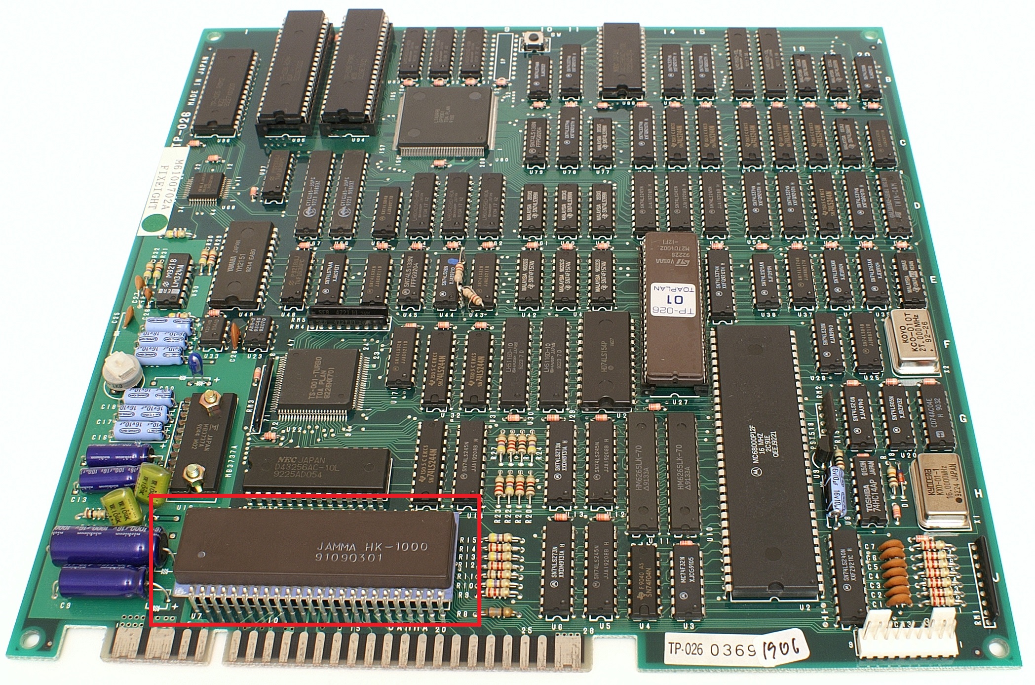
Therefore I went again for the Bprom to Gal replacement already used last year in another repair log:

Mad Gear repair log

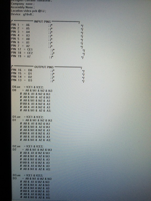
Since the prom was the very same type I replaced for Mad Gear, I converted the prom file to the PLD equations using Elgen tool U2pa and I reused the same pin configurations which fits nicely without any major hardware mod except a jumper wire to connect GND to the correct pin on the GAL

I tested the the game but I noticed something strange:

The colours were right but there were glitches on the left and right borders and also a flickering red component across all the screen (which cannot be seen on the static image offcourse)

At first I thought it was an access time problem with my GAL , therefore I burned the fastest one I had  but no luck.

I tested directly the signals of the PROMS and  found out that the CE pins were not tight to GND but were controlled by another ttl.

Soon it became clear why it didn’t work: the GAL was sending datas out of sync  therefore producing artifacts.

Since I am not a programmer I asked to Elgen and Caius (who asked to Porchy) an advice how to replicate on the PLD  a tristate behaviour.

All of them were very kind and in few minutes they informed me how tristate works on PLD equations

I added the needed modifications to my PLD equations by declaring each data pin  enabled when pins CE1 and CE2 were low.


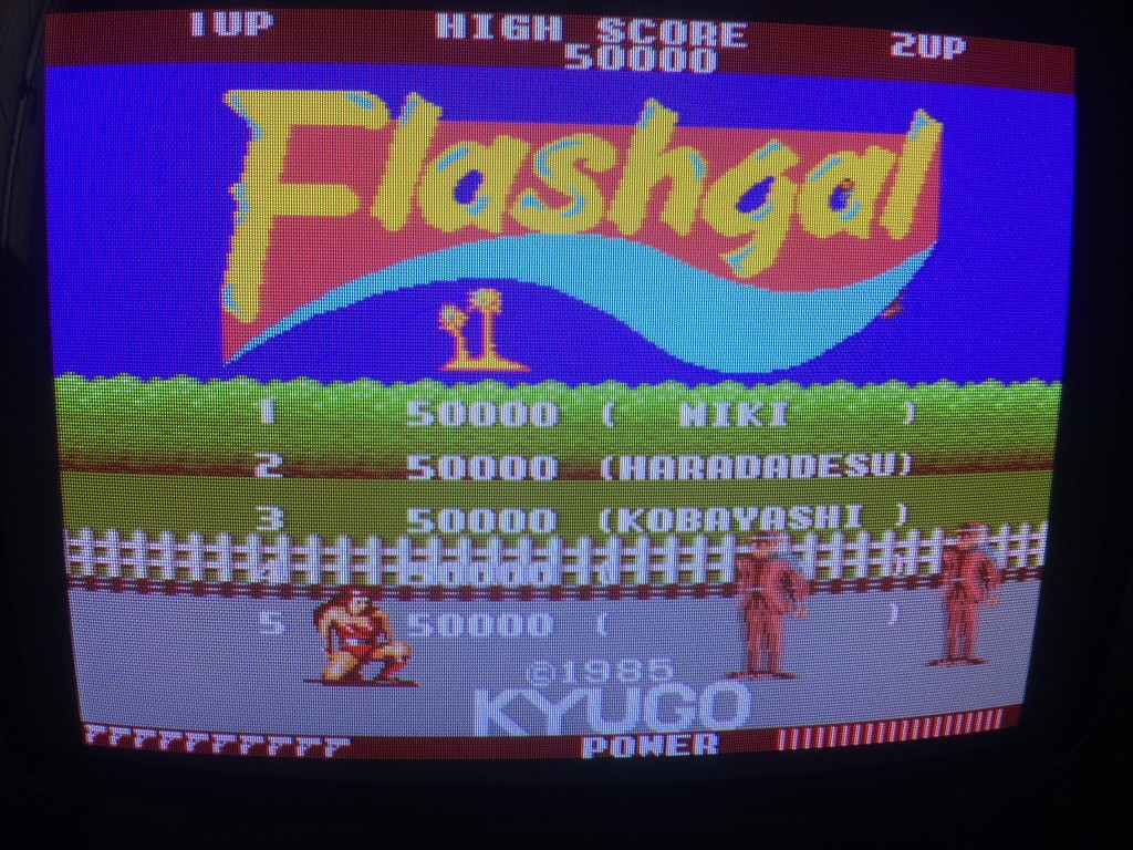
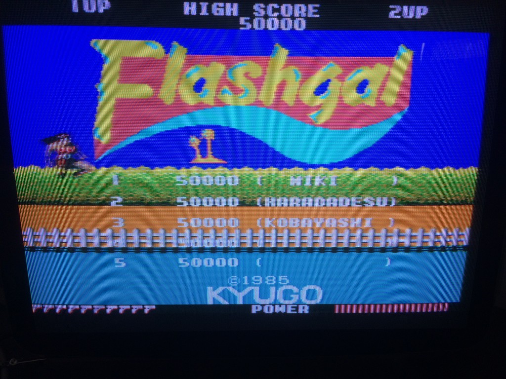
This completely fixed the colours on the pcb with no artifacts:


Again a big thanks to Elgen from https://elgensrepairs.blogspot.it/ for the invaluable tool  and to Caius and Porchy for being always very helful


Senjyo repair log

 PCB Repair Logs, Repair Logs  Comments Off on Senjyo repair log
Mar 162017
 

I bought this game declared 100% working for my collection but as soon as I fired it up I noticed something strange:


One of the mountain layer looked very strange and there was also some stripes of mountains in the sky

This game has no schematics and it is a particular complex and populated hardware with lots of TTLS and rams.

The game is on a 3 layers pcb so I had to find a way to test the components in a confortable way:


The upper board with the connector has the cpu and sound section, therefore I started to test the bottom pcbs and by shorting some signals I finally found the circuit dedicated to the last parallax layer which is near eproms 19 and 20.

All the signals looked good but the 2114 srams has some dead signals coming to 4 addresses.

Tracing back I found a Texas instruments TTL  74ls157@9C   whose outputs were all totally dead

Changing it fixed completely the background layer:


Big Fight – Big Trouble In The Atlantic Ocean repair log

 PCB Repair Logs  Comments Off on Big Fight – Big Trouble In The Atlantic Ocean repair log
Mar 162017
 

Got this rare Big Fight – Big Trouble In The Atlantic Ocean (this is the full title) PCB for a repair :

For the uninitiated game a beat ’em up which resembls Final Fight but it features also a versus mode.It was developed and published by the obscure Tatsumi manufacturer in 1992, it was one of their last arcade game before focusing on novelty sticker printing business.

The board was completely dead, I got only a black screen.The hardware is complex : two 68000 CPU, a large PGA sprites custom IC, many PLDs, lots of RAMs.Here is picture with the daughterboard removed:

Probing the two 68000 revealed no clock, master clock is generated by a 50MHz oscillator and then divided by 4 in order to route a signal of 12MHz to both CPUs:

The output of the oscillator was dead, stuck at 1.64V  :

I removed it and the its VCC pin was stuck on PCB detached from the package due rust corrosion:

Fitted a good oscillator and board sprang to life although with bad graphics:

Doing a visual inspection I found four empy sockets, according to the MAME source PCB layout and pictures on the Net they had to accomodate four TC51832 32K x 8-bit pseudo-static RAMs besides the other four present:

Once fitted the four missing RAMs most of graphics were correctly displayed but sprites were absent :

The sprites are generated by the PGA custom ‘TZB315’ (see picture above) so I went to probe the surrounding area and found discrepancies between inputs and outputs of some 74ALS245 which are in the middle of ROMs and custom data bus:

I replaced them and, although they resulted good when tested out-of-circuit, I got sprites back although scrambled  :

Sprites data are stored in eight 4Mbit 32 pin EPROMs:

I dumped them and they matched the MAME ROM set but I noticed some of them had oxidized legs:

I cleaned them and at same time replaced a device with a dodgy pin:

This fully restored sprites:

But as you can see (or better, hear..) in the above video, sound was sometimes noisy and some voice samples were missing (like helicopter when you start a game or voice of special moves and enemies).

Here a recording from a working PCB for comparison:

The background noise was due a dirty 50KOhm potentiometer, I removed and sprayed it with a contact claner :

Voice data are stored in a 2Mbit EPROM and played by an OKI MSM6295 (corean rebadged one on this PCB)

The dump of the EPROM was good, I also replaced the OKI with no luck.Probing the EPROM revealed that pin 30 (address line A17) was always LOW so the second half of the voice data could be not accessed.Doing a check with my multimeter revealed thas this pin was tied to pin 22 (/CE), this obvioulsy sounded me weird.Near the EPROM there was a jumper installed @JP4:

Looking at PCB pictures on the net I had confirm that the jumper had to be set in this configuration.But looking at its solderside I noticed a trace which connected  the central pad to the left one.This obviously, along with the jumper installed in that position, caused the short between the left and right pad resulting the two signals being tied together.So, I cutted this trace:

This restored the missing voice samples.No further issues were found so board 100% working.

 Posted by at 12:22 pm