Got a familiar Operation Wolf PCB that I offered to look at for a friend.
I’ve had this board several time over its life and this new fault was “no sound”. The sound actually stopped working when the owner hit the start button but the game could still be played.
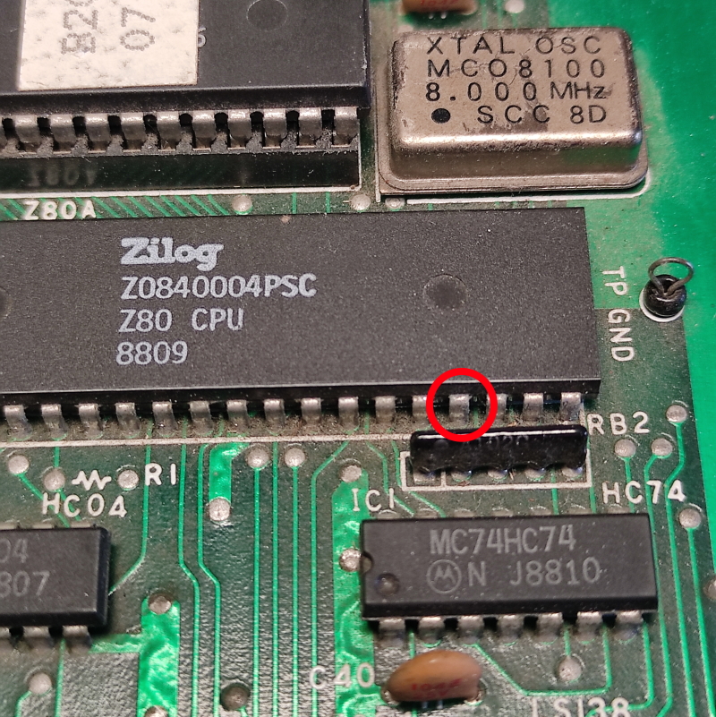
I found the fault really quickly. Starting at the CPU I checked all the signals on the Z80.
Everything was doing what it should be doing except for the /NMI pin (pin 17) which was stuck high all the time.
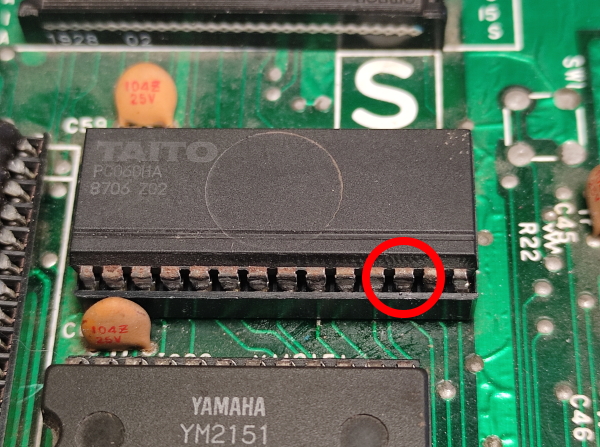
The NMI is used to signal to the sound CPU to start playing a sound. The signal is generated by the custom PC060 chip nearby on pin 12
I transplanted the custom from my Rainbow Islands PCB to test and the sound all came right back.
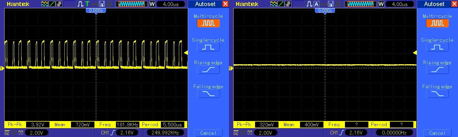
Here you can see and hear the /NMI pulse as a new sound plays
So now I’ve confirmed the device at fault what do I do for a replacement. I have no scrap boards with one available. Furrtek has recreated the operation of this device and Caius has made a CPLD replacement that uses this code.
I’ve recapped the sound section and Caius is sending me a replacement but for now I’m happy that this is working again.
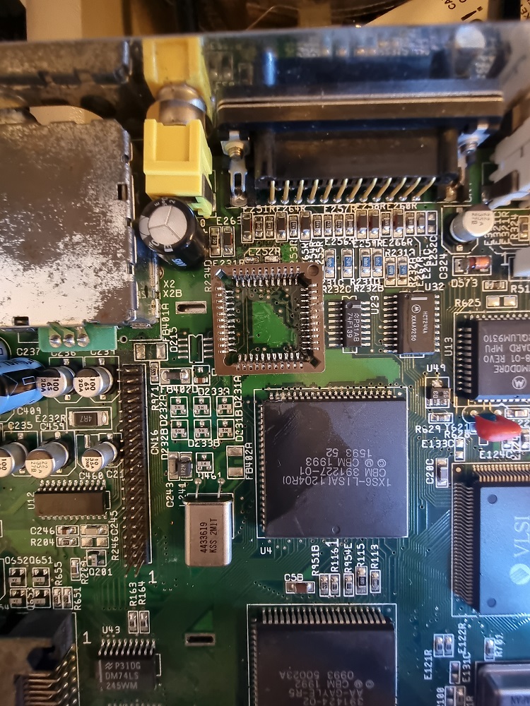
Sockets arrived yesterday and chips arrived a day later, great timing because I’d already had the socket installed by the time the chips arrived.
I’ve decided to remove the backing on one of the sockets, I really didn’t like the idea of trying to get my soldering iron tip in between the backing and pins so I removed it. My plan was to attach some double sided tape or hot glue to the backing/shim then apply it to the MB later, I didn’t want the chip to sit so low in it’s socket in case it needs to come out later.
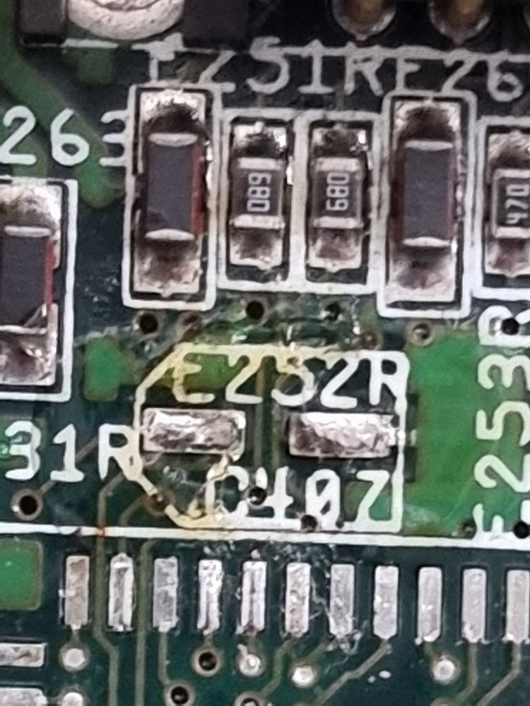
After lining up the pins, I had an obvious problem here. The base of the SMD capacitor at C407 in the video decoupling circuit wont allow the socket to sit flush so I decided to remove it, solder the socket in place then add the capacitor later.
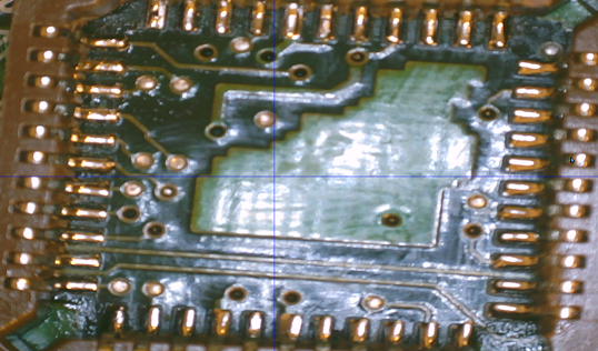
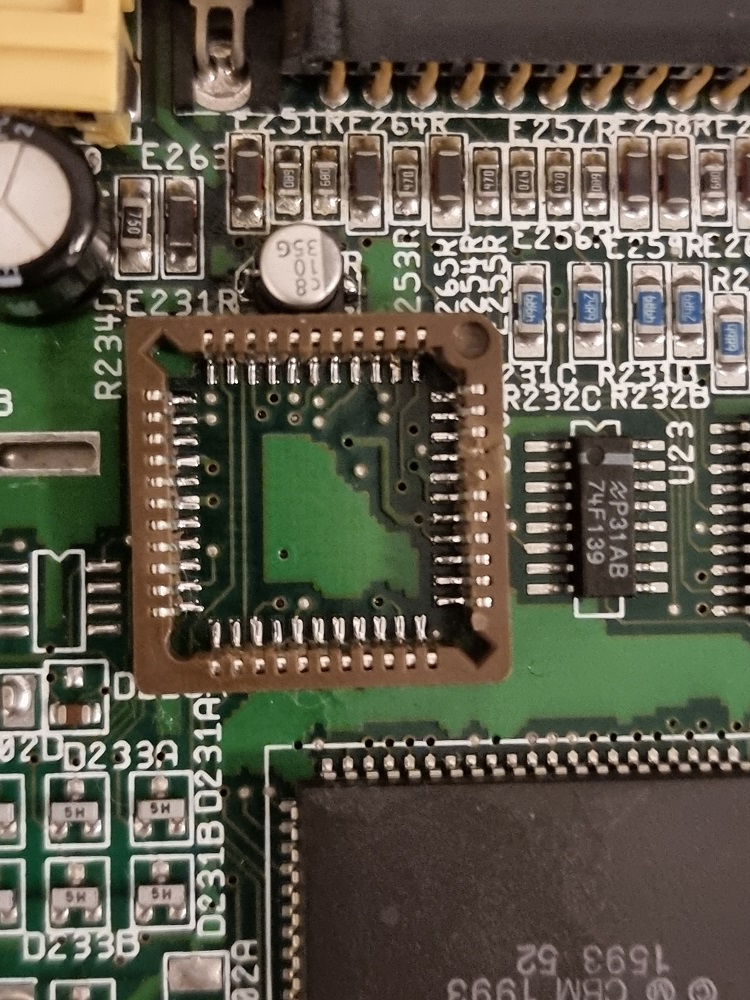
Out with the old and in with the new. Socket soldered into place and connections inspected with a Microscope, then the 10uf capacitor replaced with a brand new one.
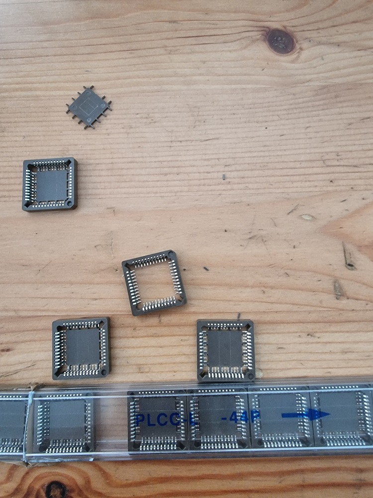
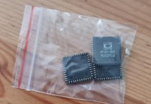
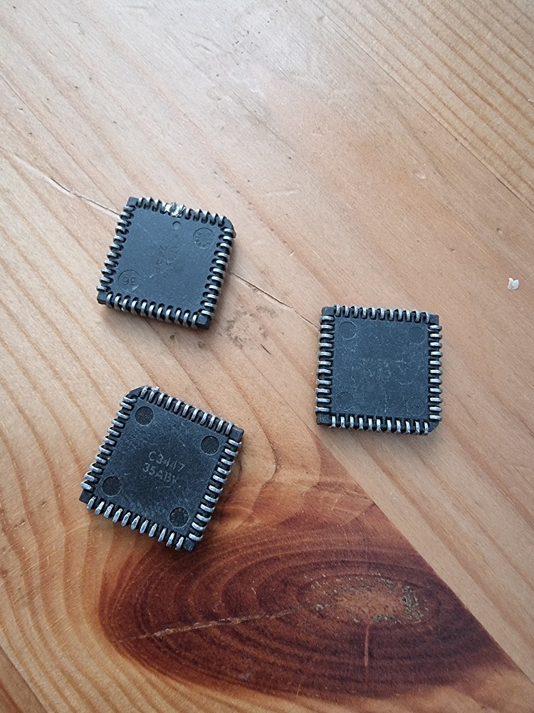
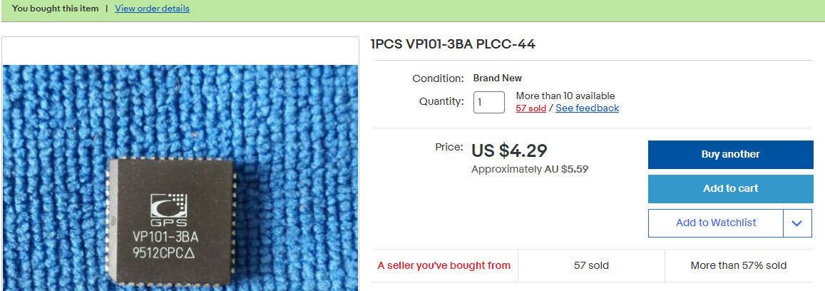
The following day later in the afternoon I received a package containing these. Who sends electro static sensitive devices in a plastic satchel ? More over the devices were clearly de-soldered/pulls yet advertised as new. Will avoid this seller in future.
I chose the cleanest of them all ( top right ). I then installed the plastic shim with some double sided tape to the bottom of the socket and installed the chip and tested with success.
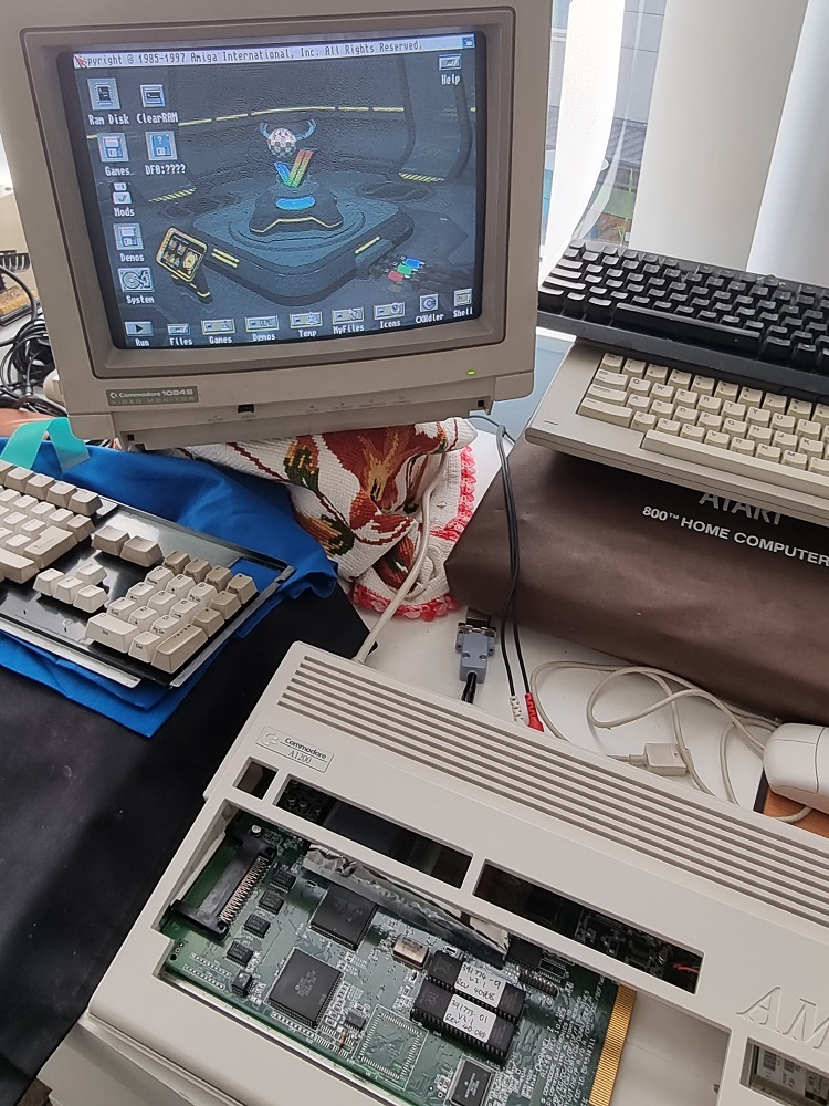
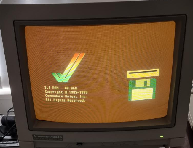
Whilst installing and carelessly adjusting my CF card in my A1200 with it switched on, I managed to short out some component on the motherboard via the shield which caused the machine to reboot and then come up with the following screen.
You can clearly see that blue is completely missing.
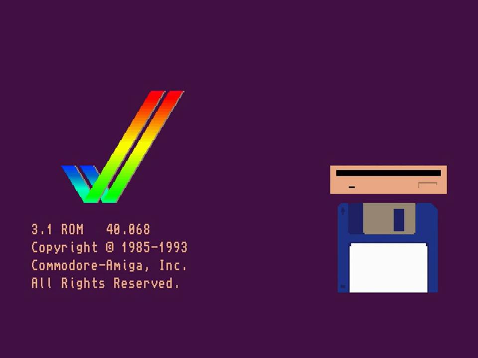
A healthy kickstart screen should look like this
I wasted no time getting to work after cursing myself for 30 minutes or so and feeling bad all night.
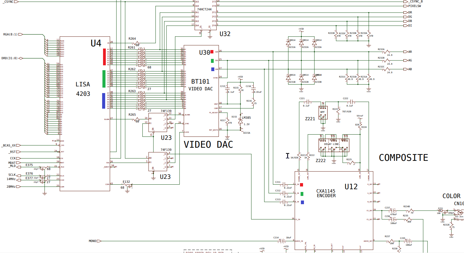
1st step was to figure out where the fault actually was, so I consulted the schematics to understand the design and get an idea of where to start.
I have clearly marked the important parts of the drawing by marking each of the 3 RGB colours over the signals. First of all, we have an AGA ( Advanced Graphics Architecture ) custom chip called LISA which generates the colour information internally amongst other things, this must be converted to analog via the video DAC which accepts 24 bits of colour information from LISA and then passes those analog signals directly to the 23pin D-SUB connector on the back of the A1200.
The same 3 RGB signals generated by the video DAC are passed to the Sony Encoder chip for composite signal and also RF out to a TV.
The issue was also reproduced on the composite out, this would confirm the encoder just gets its RGB signals from the DAC and to look elsewhere. Unlike the Amiga 600 design which uses no DAC but uses the same encoder to pass RGB to the 23pin D-SUB, the A600 video output design is similar to the video hybrid method used in the A500 for generating RGB.
Thankfully we have a similar problem here from RetroGameModz that I used as a reference which describes the troubleshooting process. I really liked his use of Protracker to trouble shoot the colour, this proved very useful.
In Protracker, I turned Red and Green signals to the absolute minimum and adjusted the slider for Blue and see no change at all. So with my scope I verify the signals coming out of pins 25,26 and 26 of the video DAC. These are labelled IOR,IOG and IOB respectively. I could see valid waveforms on both on IOG and IOR but a flat line ( low ) on IOB no matter where I positioned the blue slider in Protracker via setup from the main menu. This explains the lack of blue.
So either, the 8 bits for blue were stuck on the output of LISA or I had a bad video DAC.
I then attached my logic probe to 5v somewhere inside the machine and adjusted the slider in Protracker whilst probing R,G and B signals. To my relief my logic probe responded to each and every single one of the 24 bits coming out of LISA. So LISA was spitting out colour information but the DAC was obviously not going to deal with blue. I repeated the same measurement on IOB output of the video DAC this time with the logic probe which shows its held low regardless of the position of the slider, further confirming the lack of waveform there with the scope.
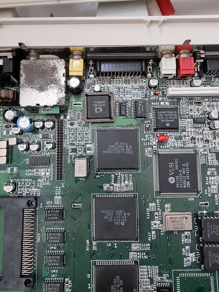
I wasted no time ordering some replacements. 3 x VP101-3BA manufactured by GPS/MITEL and some 44pin PLCC sockets.
So currently waiting for these to arrive from China, delivery time is 2 months.
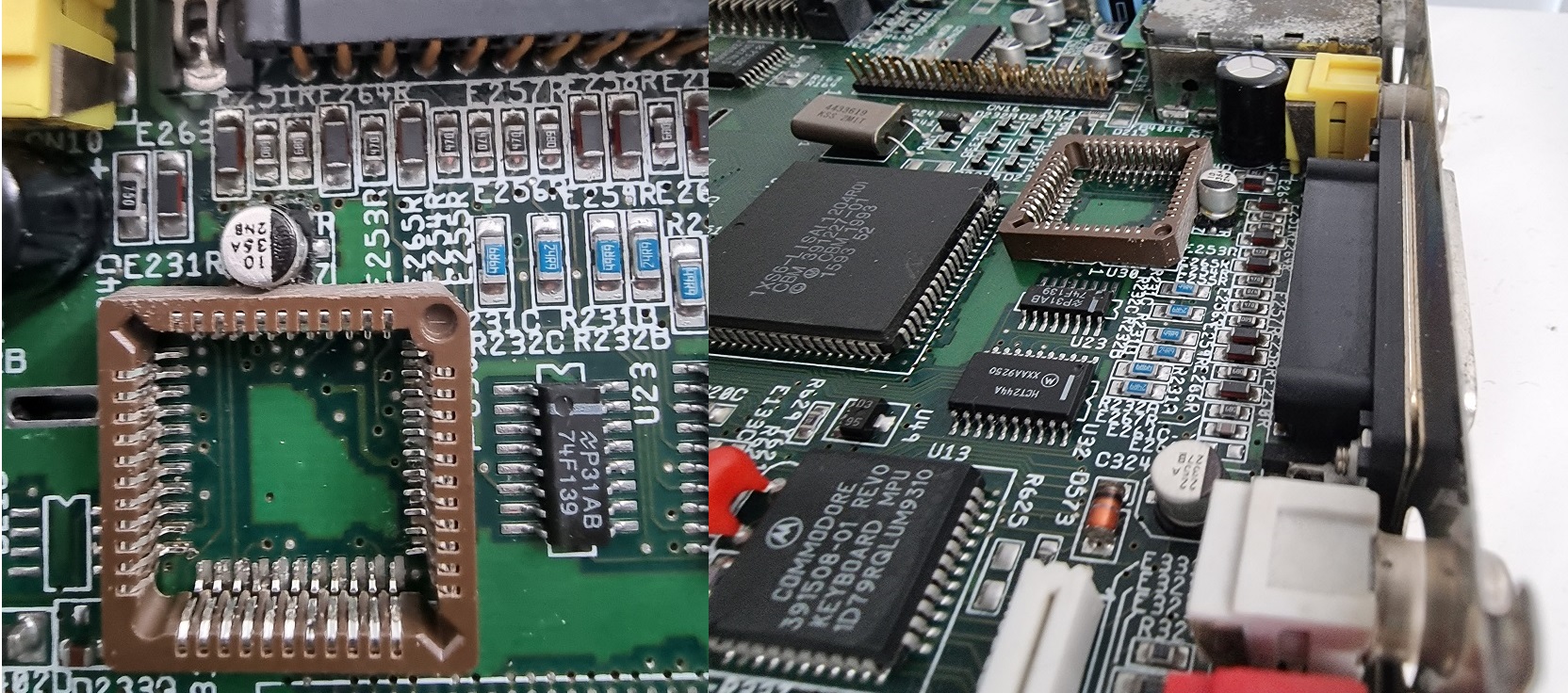
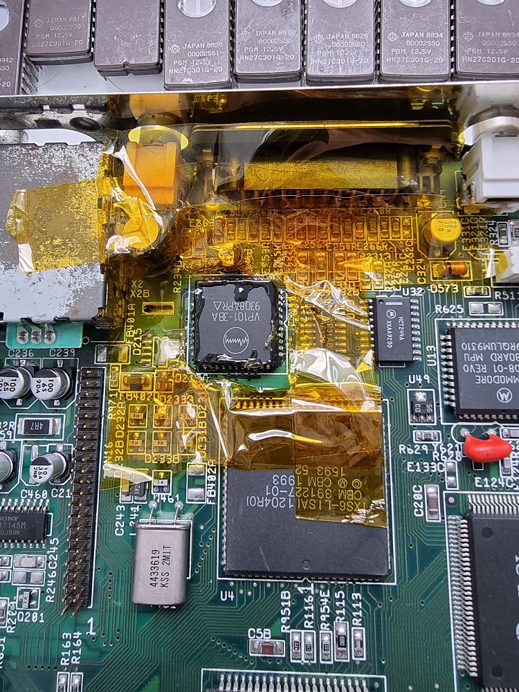
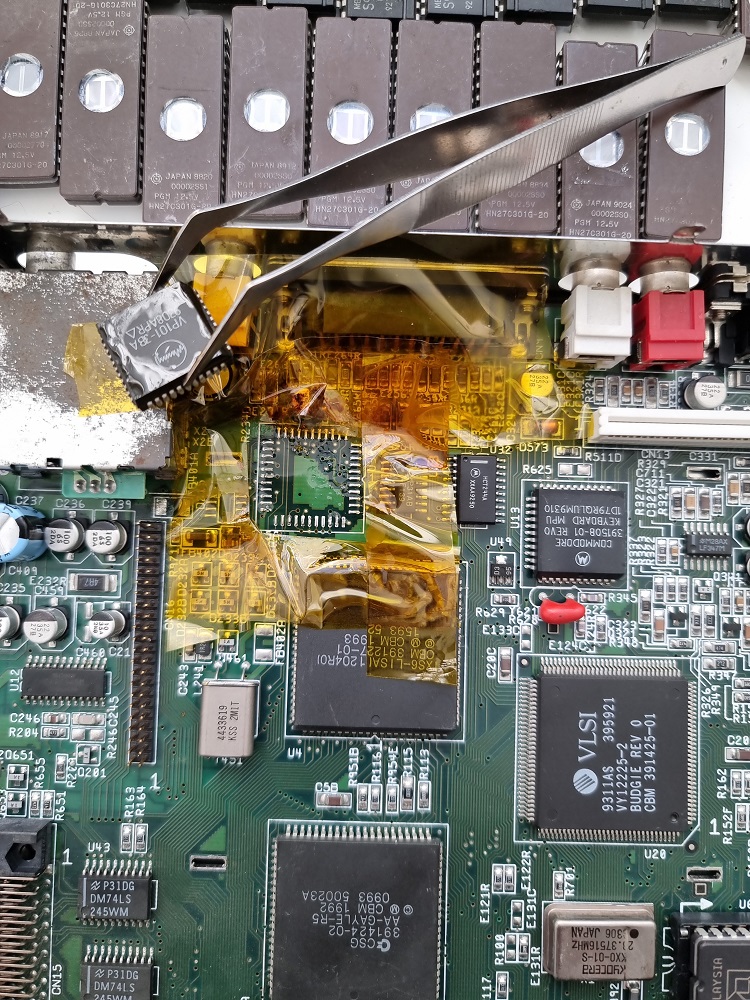
And in preparation I couldn’t wait to remove the faulty component from the A1200. First step was using a liberal amount of polyimide tape ( this stuff is expensive but will save you from grief ) to protect surrounding components from heat exposure, I applied some flux and then heat the chip to around 200 for 1 or 2 minutes, then raised it temp to 350 to finish off.
I had this cleaned up nicely. Now just waiting for the spare parts to arrive for a part 2.
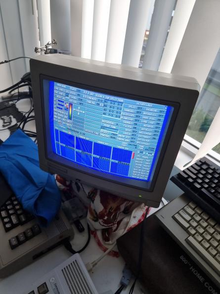
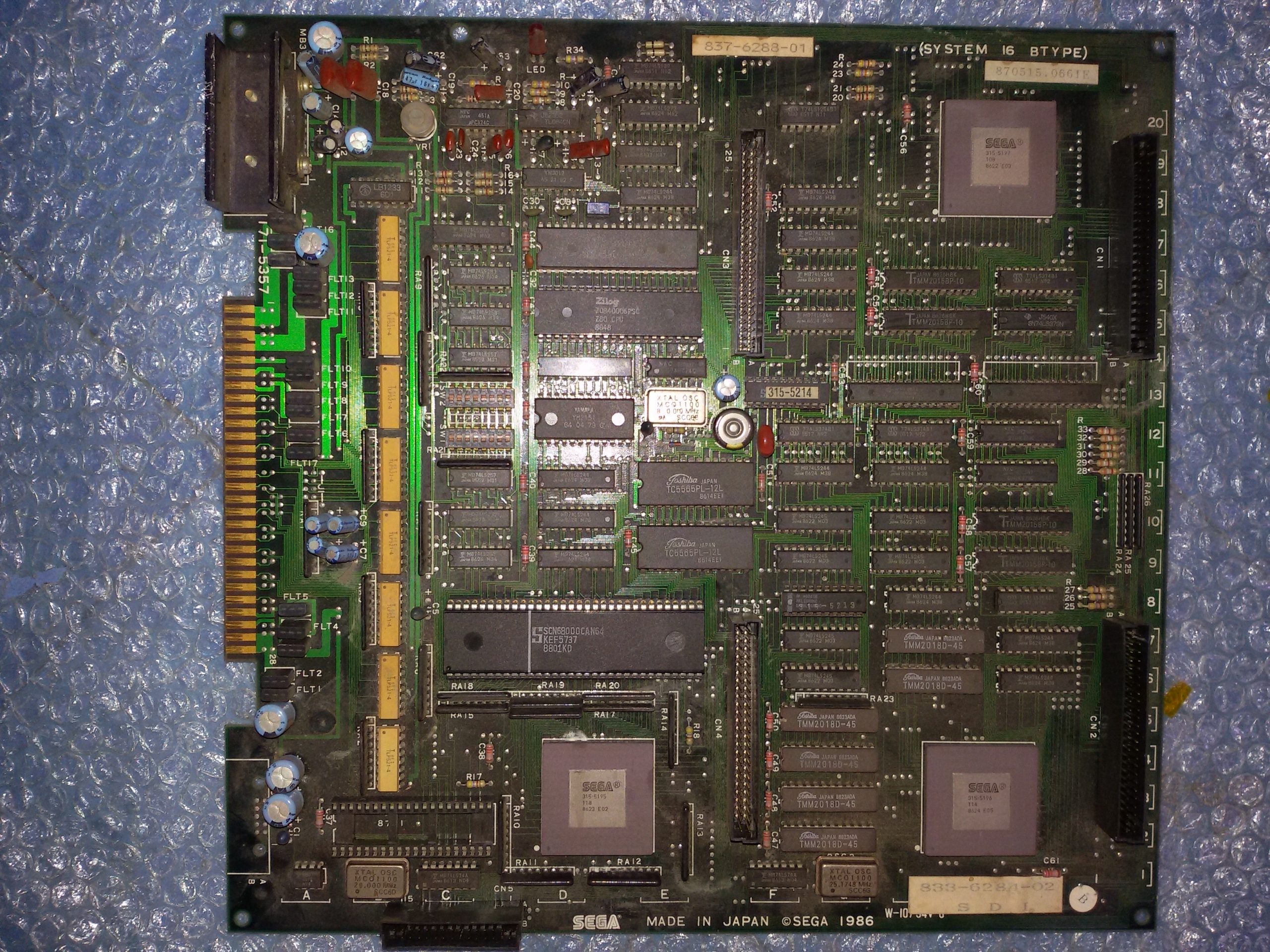
Lately I’ve gone through all the faulty/untested PCBs I never looked at (tons of them…) to check if there was something that was worth a repair.I found this Sega System 16B motherboard :
I plugged in a Golden Axe (conversion) ROM board and powered up the set.Board booted up, game was playable with good graphics but sound was missing :
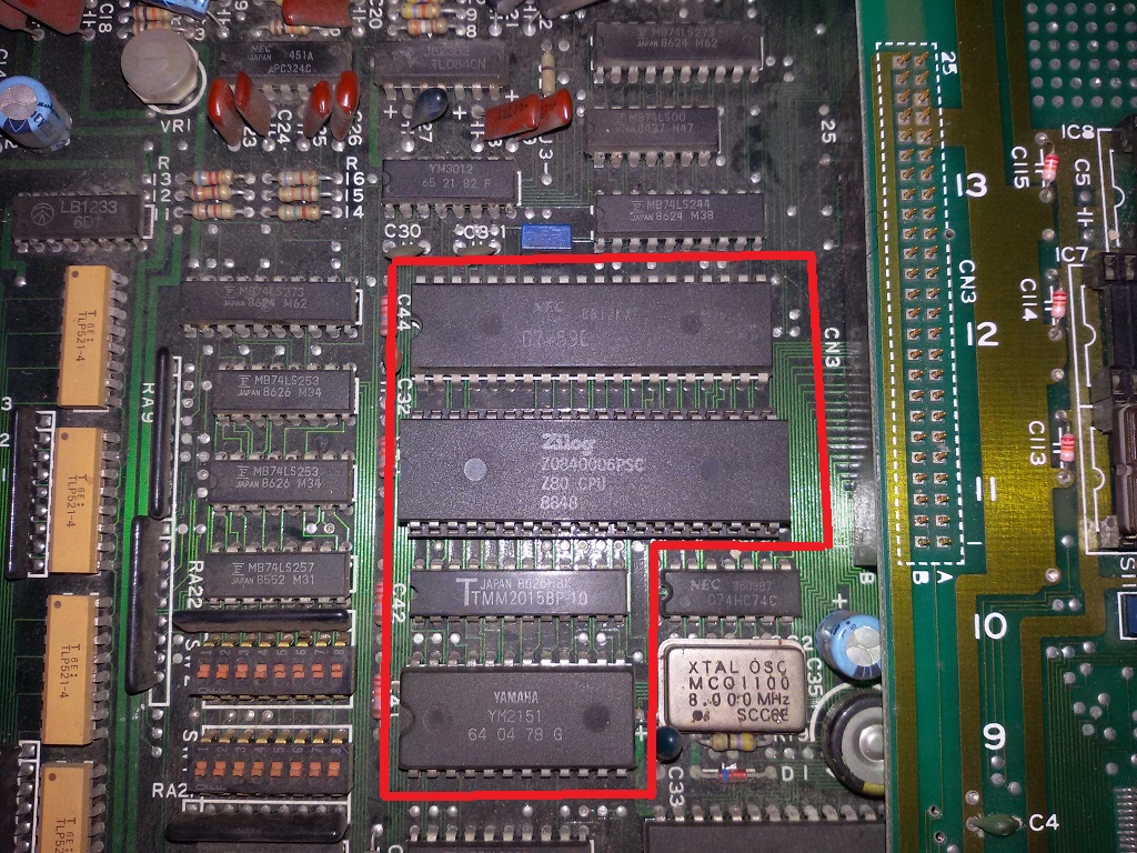
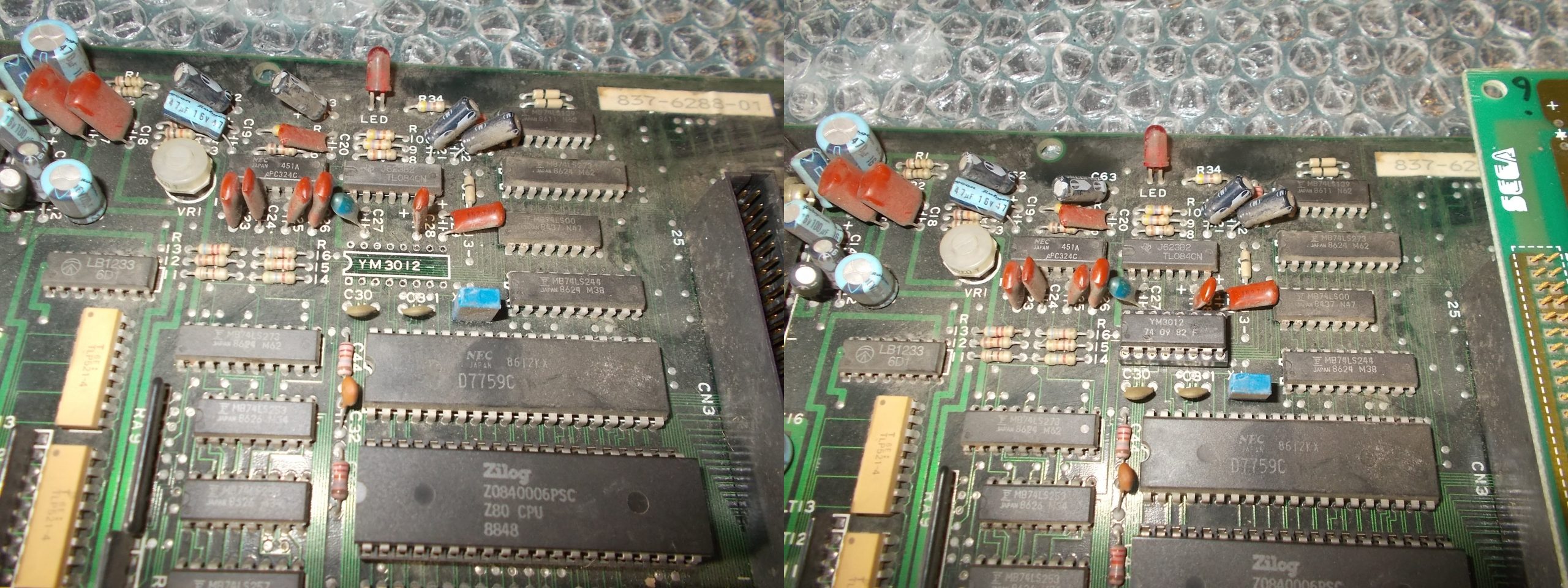
The audio hardware is made of Z80 CPU plus a Yamaha YM2151 for music (and a NEC uPD7759 for speeches) :
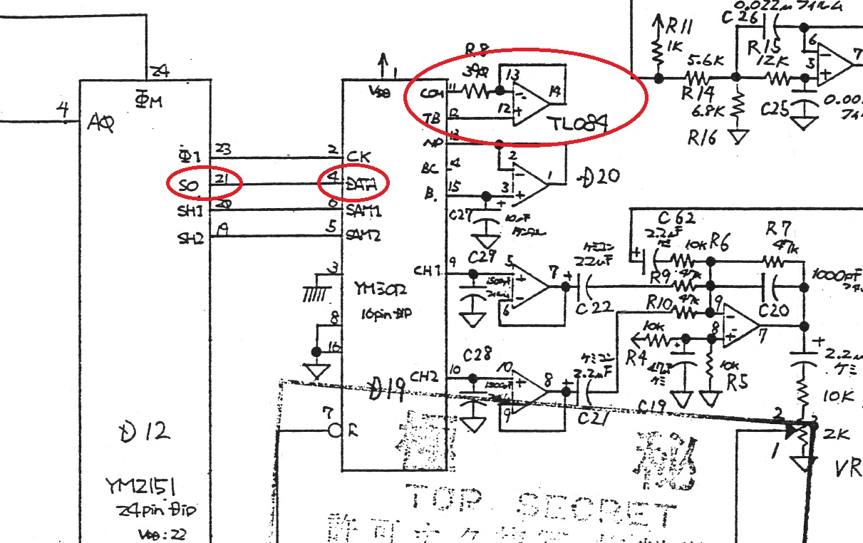
Looking at schematics the serial data from the YM2151 (pin 21) is sent to the YM3102 DAC (pin 4) which then routes the analog signal to the TL084 OP-AMP :
Probing with the oscilloscope revealed the YM2151 serial data were present on the input of the YM3012 (pin 4) but the output (pin 11) tied to the OP-AMP was silent :
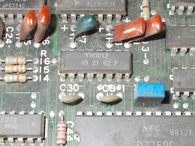
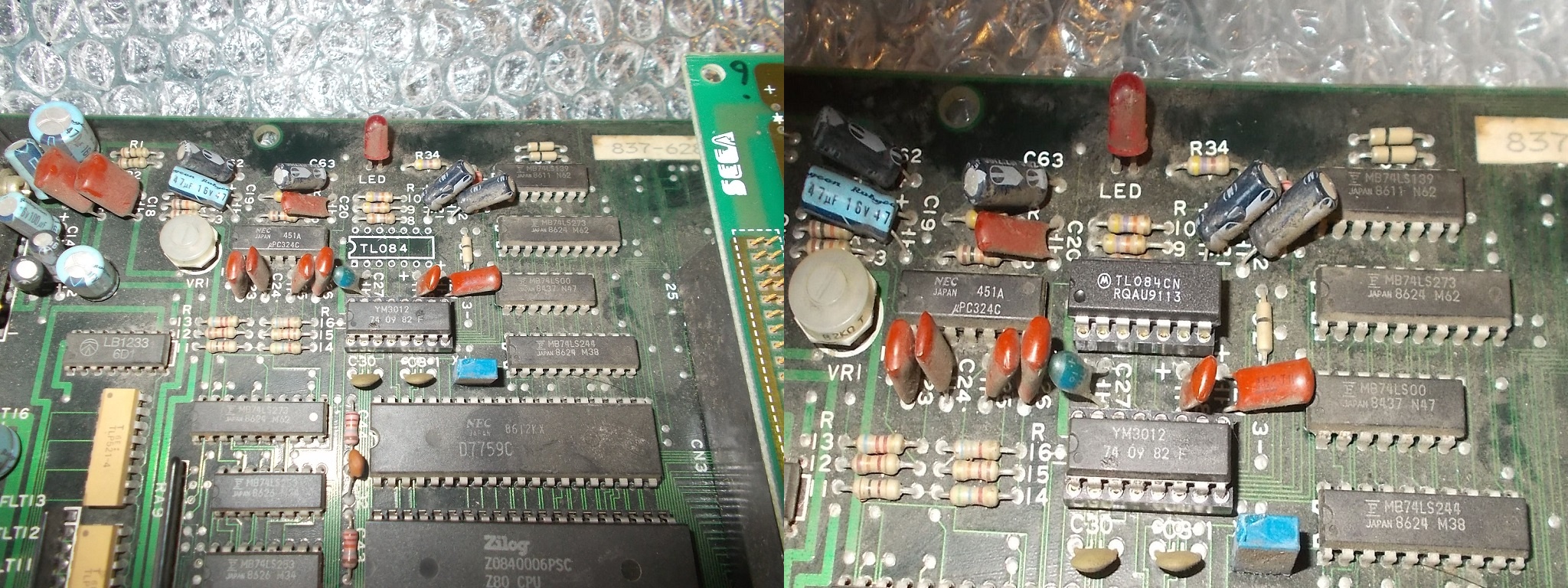
The DAC was likely fault so I replaced it :
This brought the sound back but it was faint and corrupted (except the speeches that was fine) :
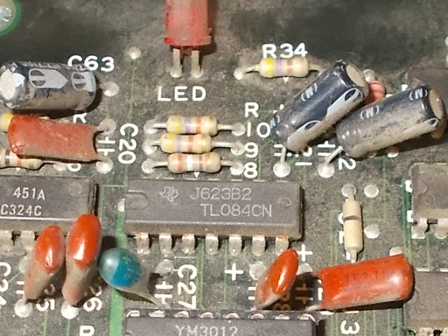
The TL084 OP-AMP is the only part between the DAC and the final sound output :
It’s a well known prone to failure part so I went straight to replace it :
The sound was completely restored and board 100% working.End of job.
PCB Repair LogsComments Off on Passing Shot (Sega System 16B) repair log
Oct122020
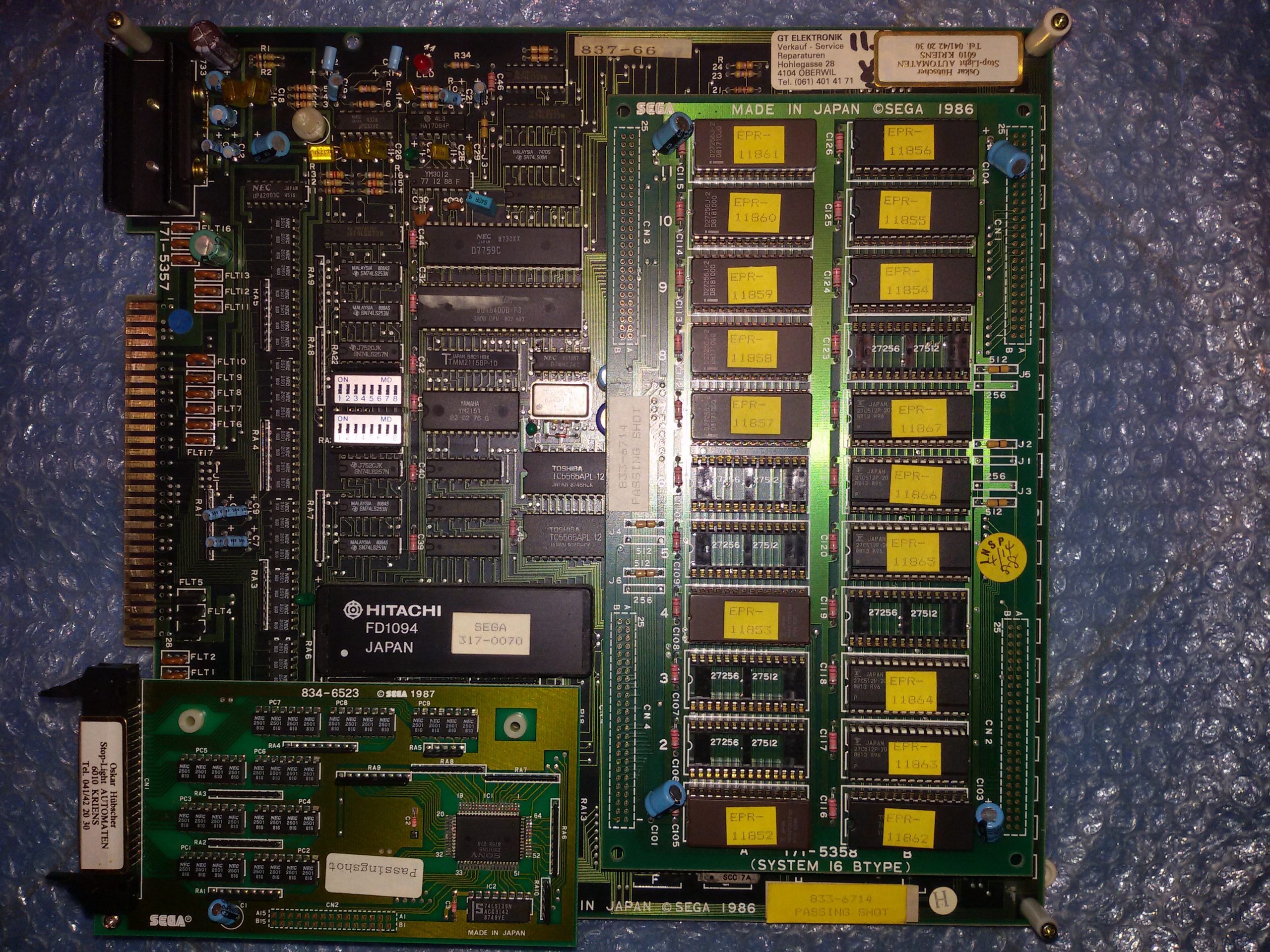
Got an original Passing Shot PCB for repair, as you may know it’s a tennis game released for System 16B hardware by Sega in 1988.
Board had its ‘FD1094’ battery-backed custom CPU module which was still alive since the board booted but sound was missing at all:
These are the times when an audio probe really comes in handy in diagnosing the fault helping you to figure out the nature of the lack of sound (if digital or analog).So I fired up this tool and started to listem to various points of the audio circuit :
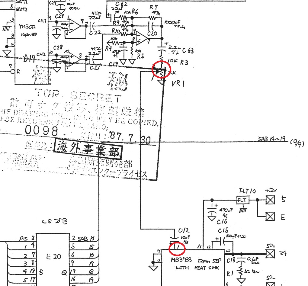
For first I probed the outputs of the YM3812 DAC and I got sound from them, this meant the fault was in the analog circuit.Looking at schematics I followed the path, the sound was still present on the input of the volume potentiometer :
But then it was silent on the output which gives the signal to the Fujitsu MB3733 amplifier :
Schematics shows there is nothing between the output of the potentiometer and the input of the amplifier (apart from a 10uF electrolytic capacitor that was tested as good)
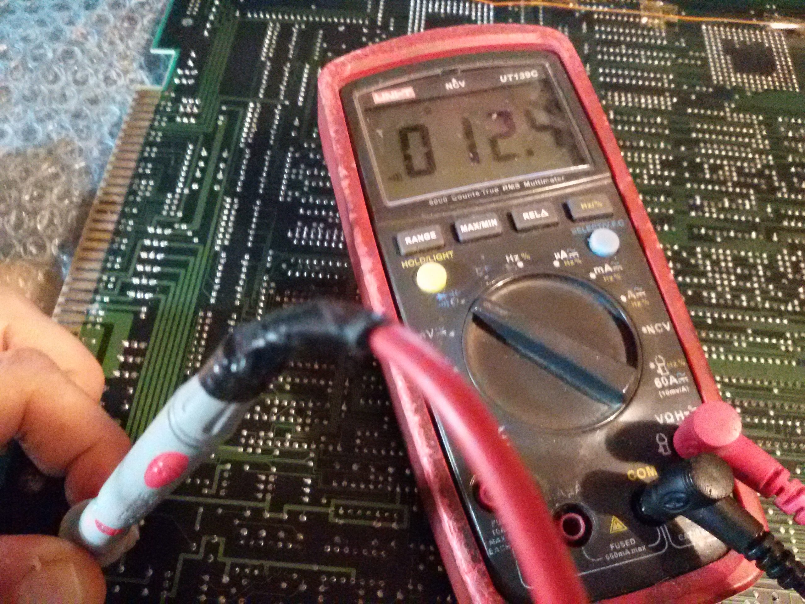
Metering the amplifier I found that pin 1 ( the input which takes the signal from the potentiometer) was almost shorted to pin 11 (+12V supply), there was only 12.4 Ohm of resistance :
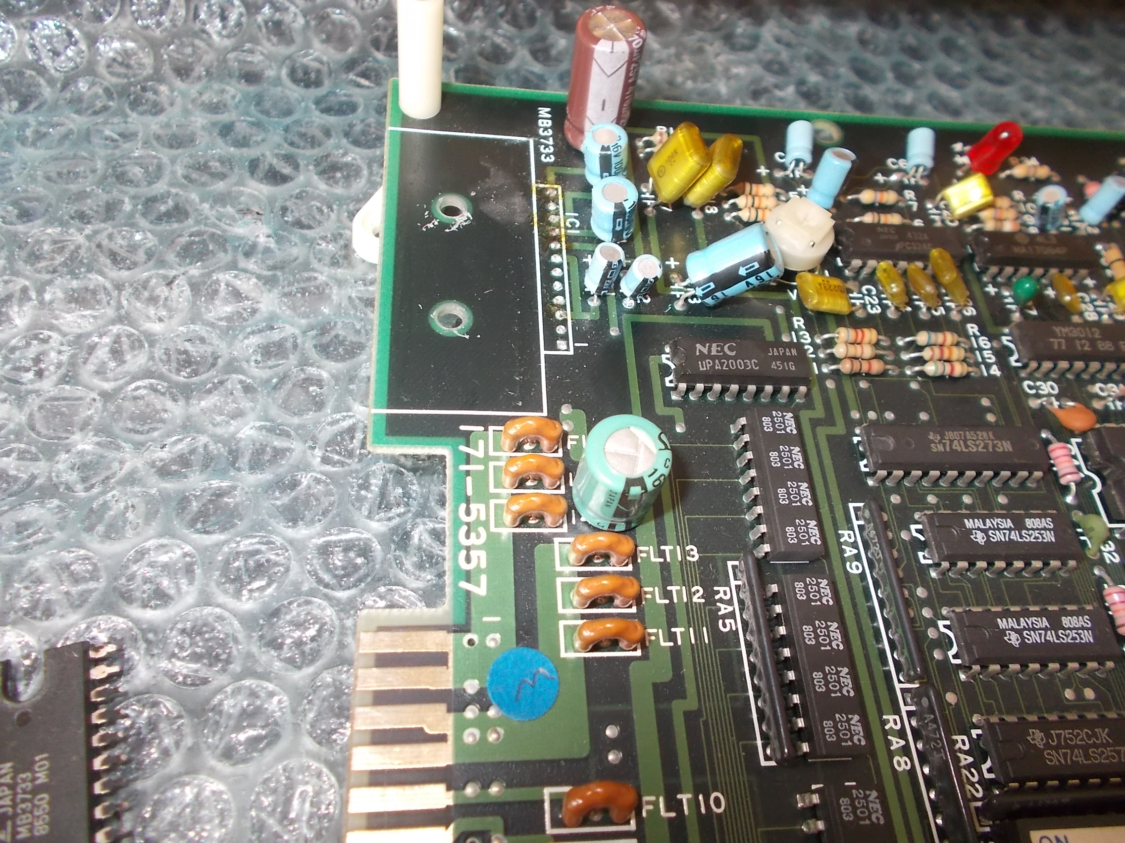
The amplifier was likely bad so I removed it :
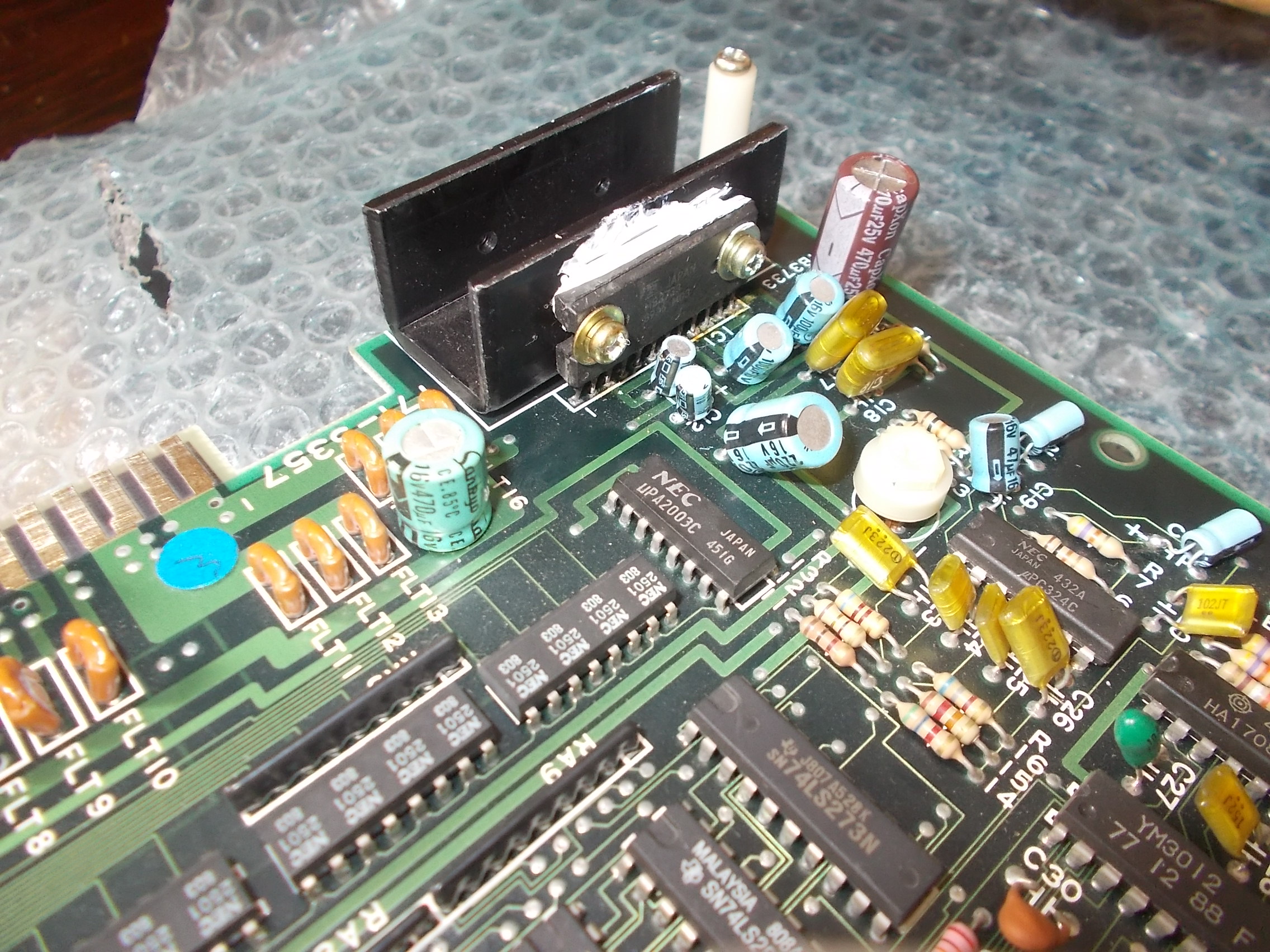
And replaced it putting also some thermal silicon grease for a better heat dissipation :
I powered the board up again and the sound was back.No other issue found hence I could declare this board 100% fixed and working.