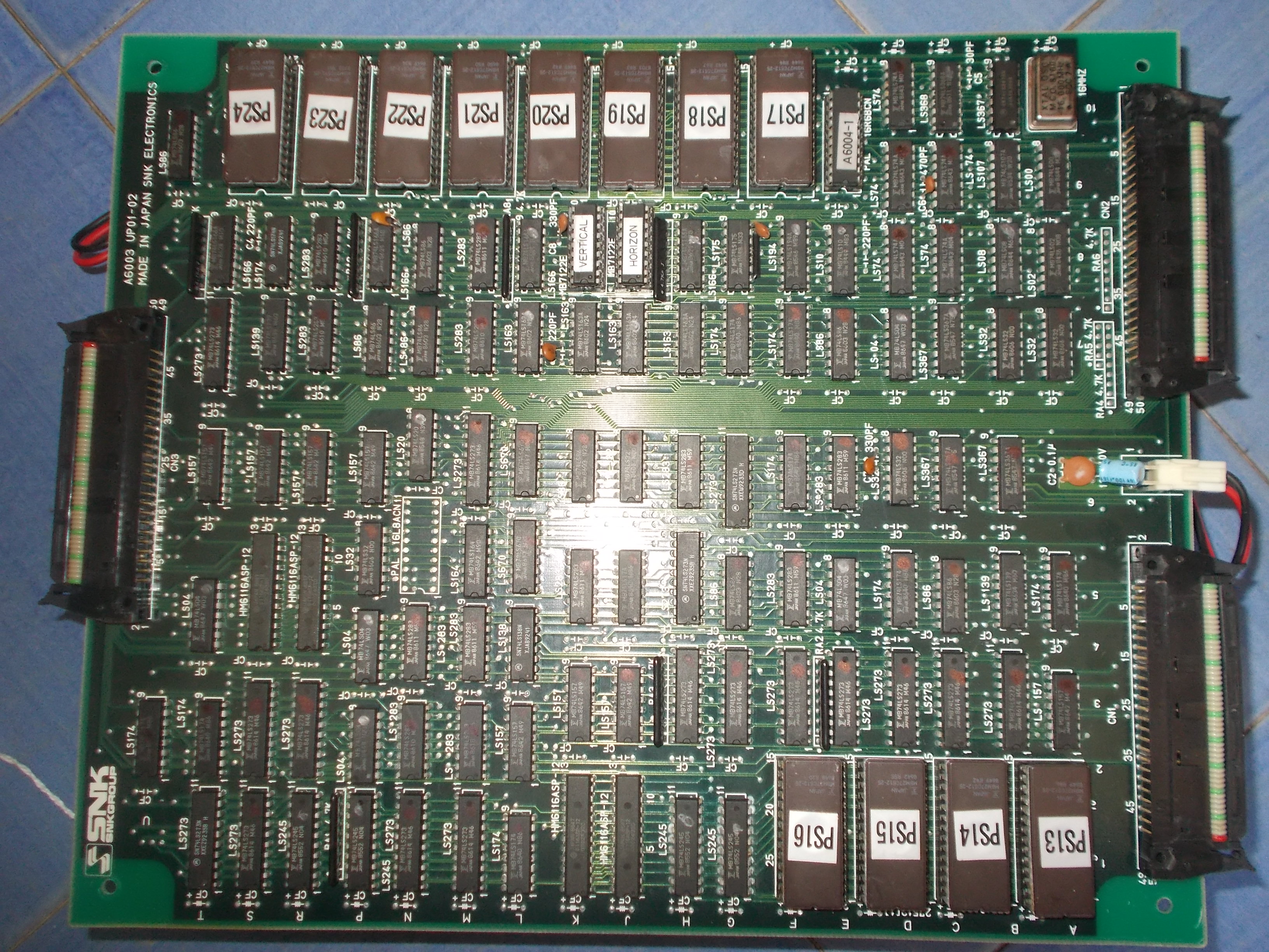
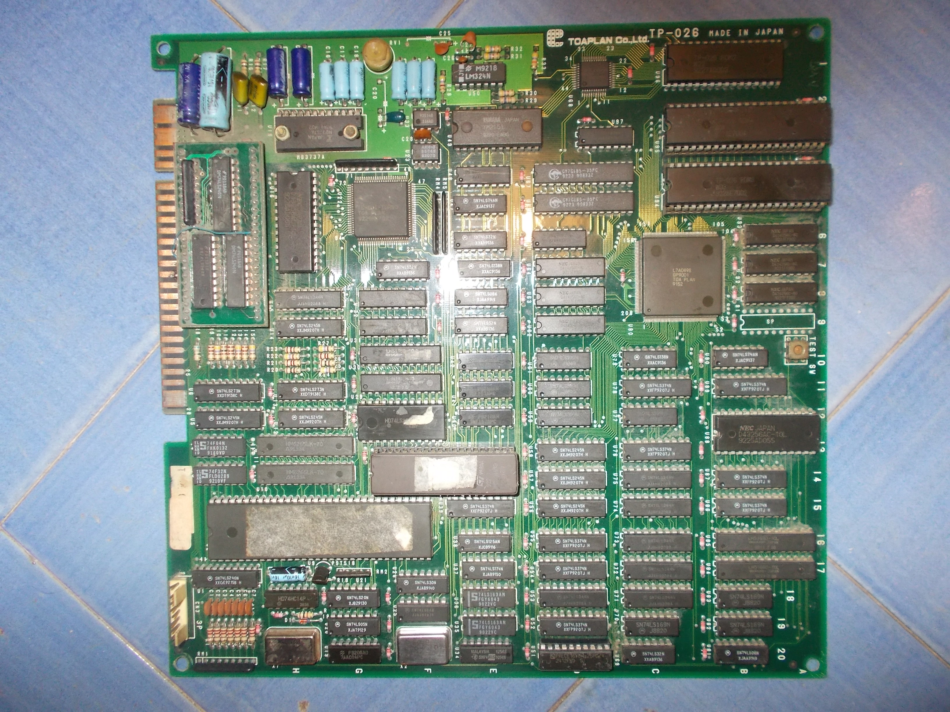
I’ve been sent from Germany some faulty PCBs for repair.There were among them two PCBs manufactured by Toaplan :
- Knuckle Bash
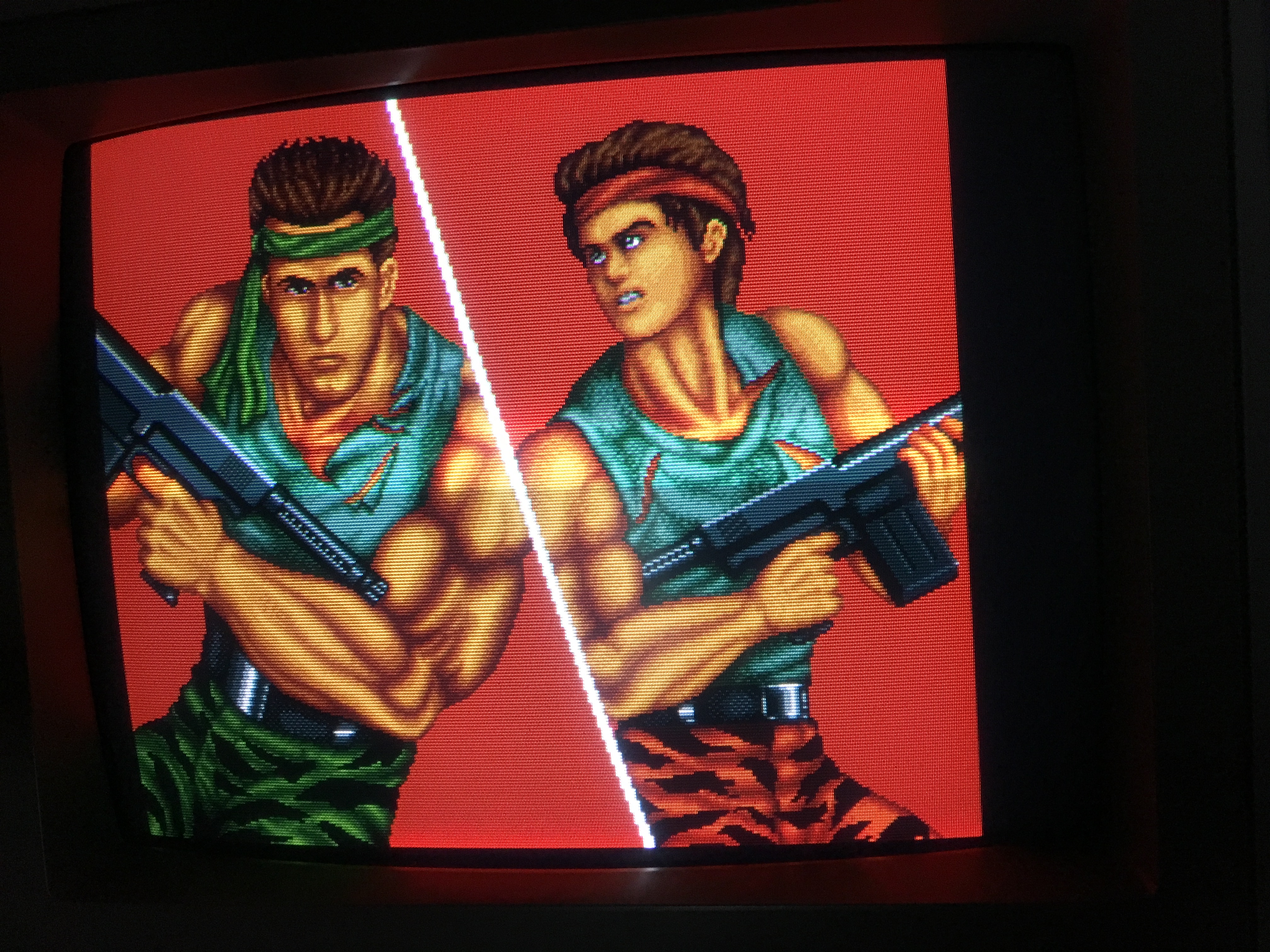
- Fixeight:
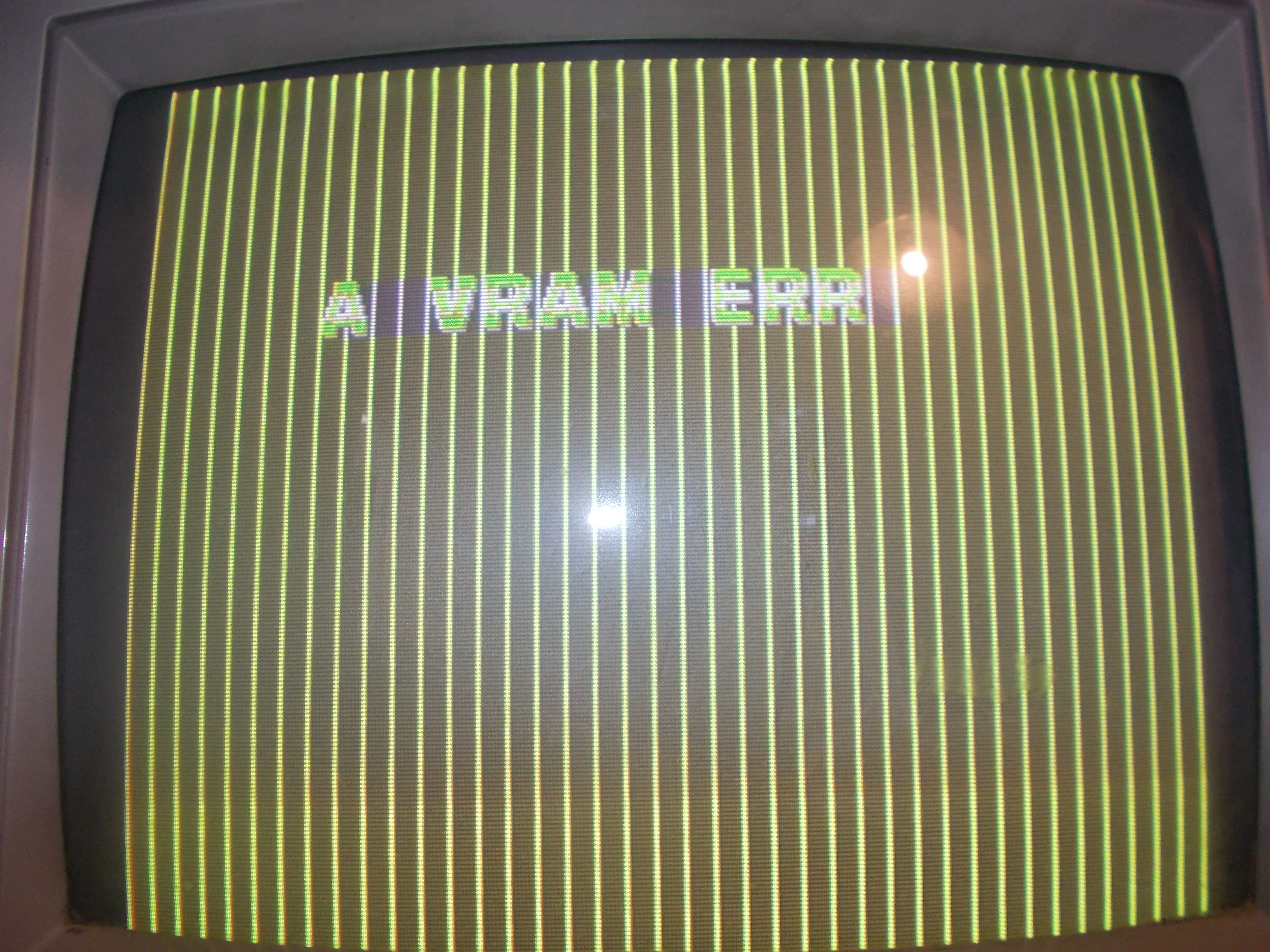
The first was throwing a “A VRAM ERR” message on boot:
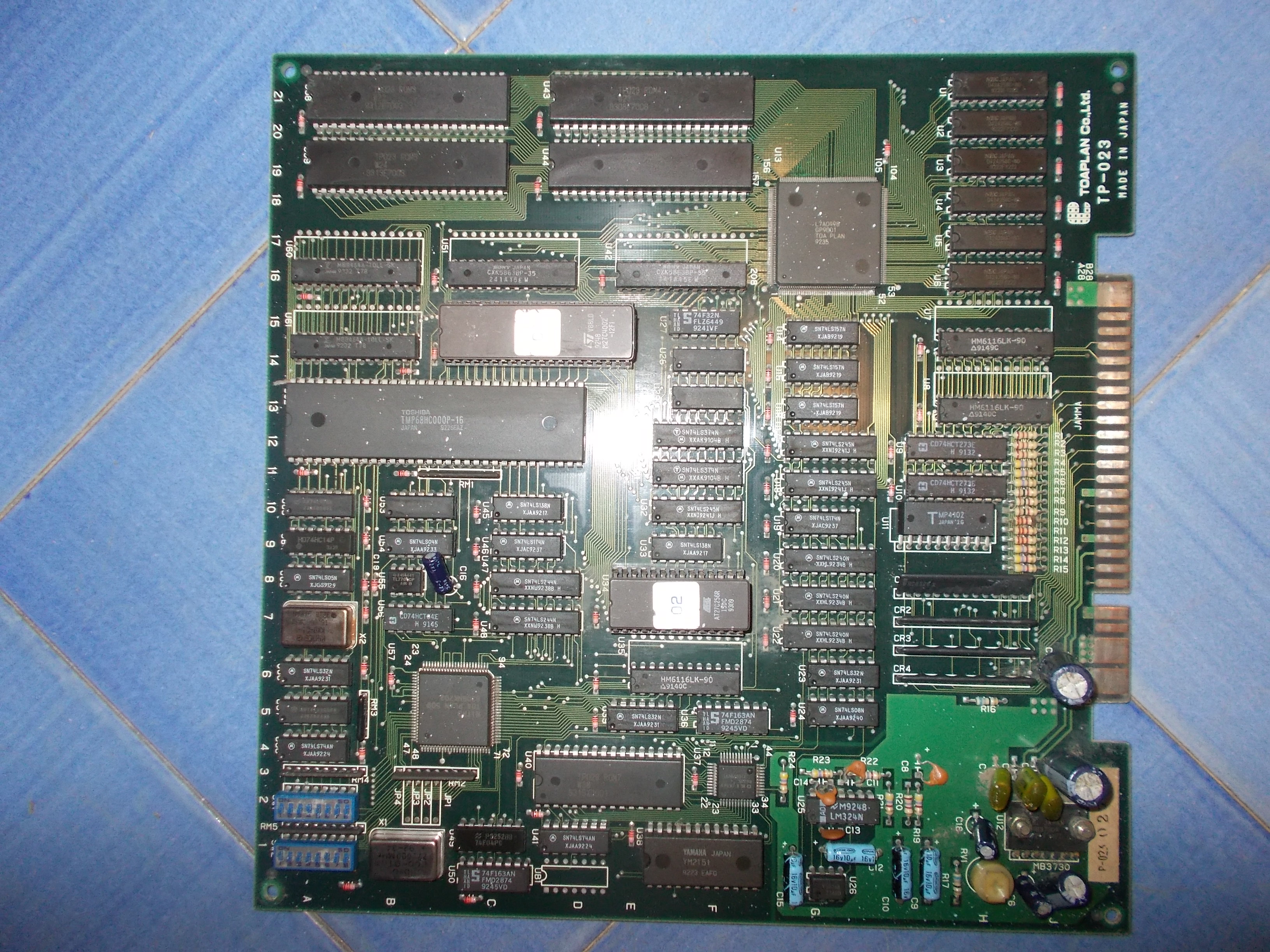
The video RAMs (VRAM stands for this) are two 8k x 8-bit static RAM located @42 and U51:
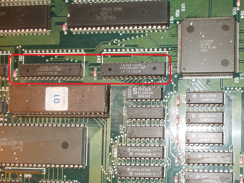
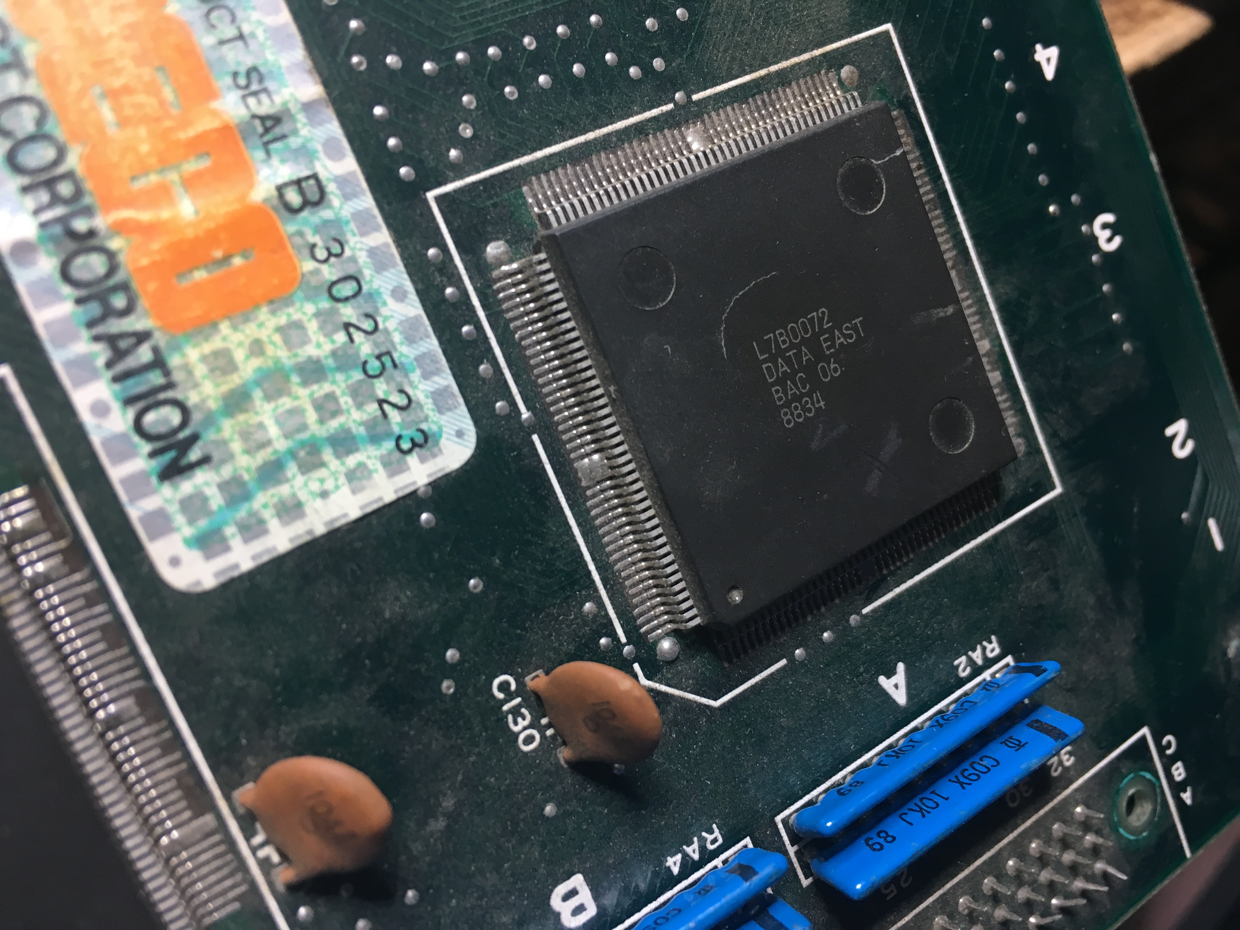
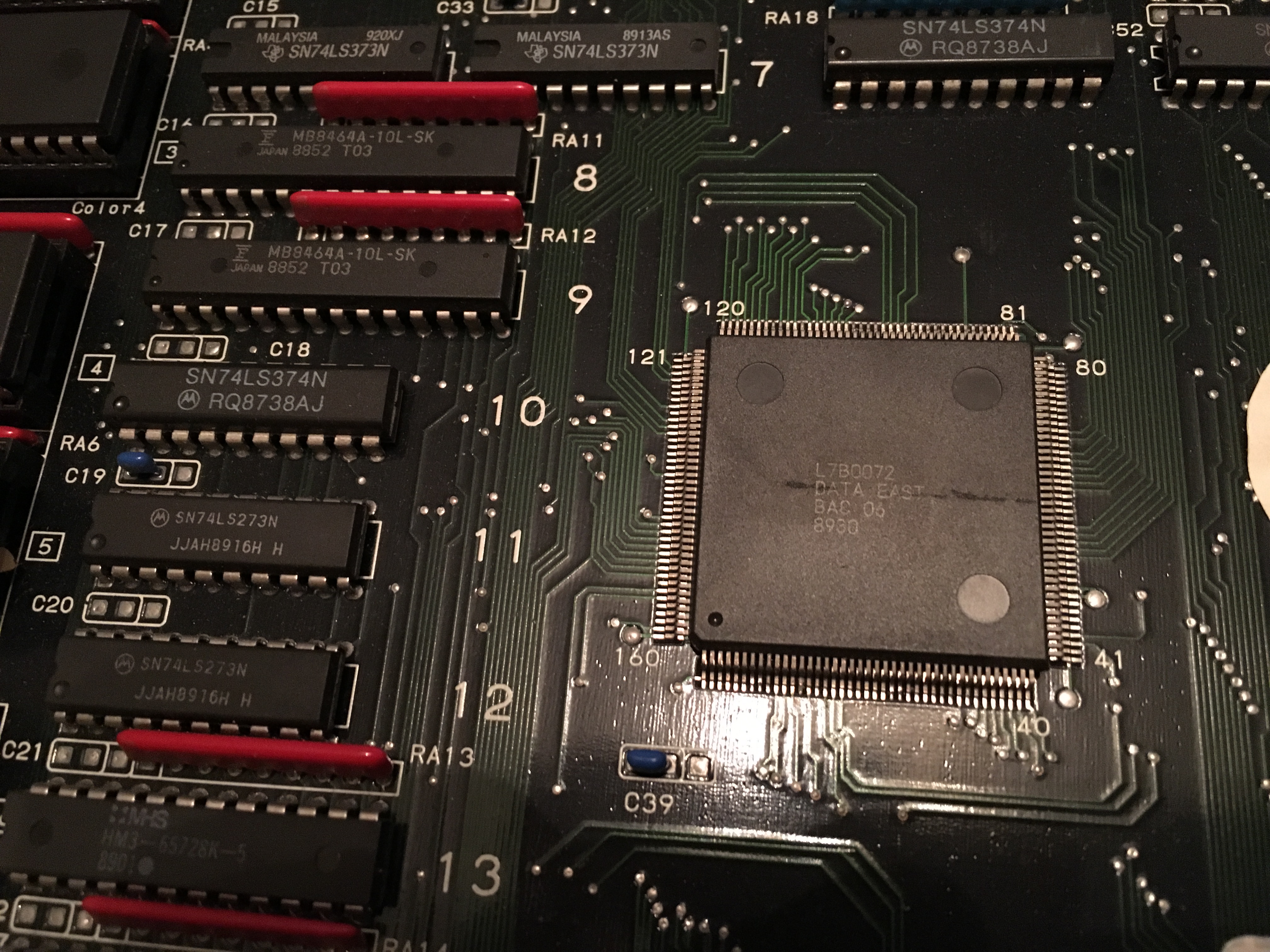
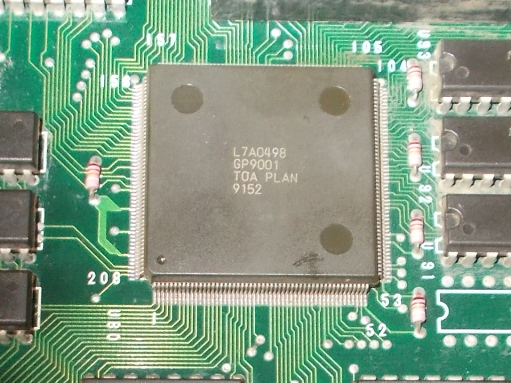
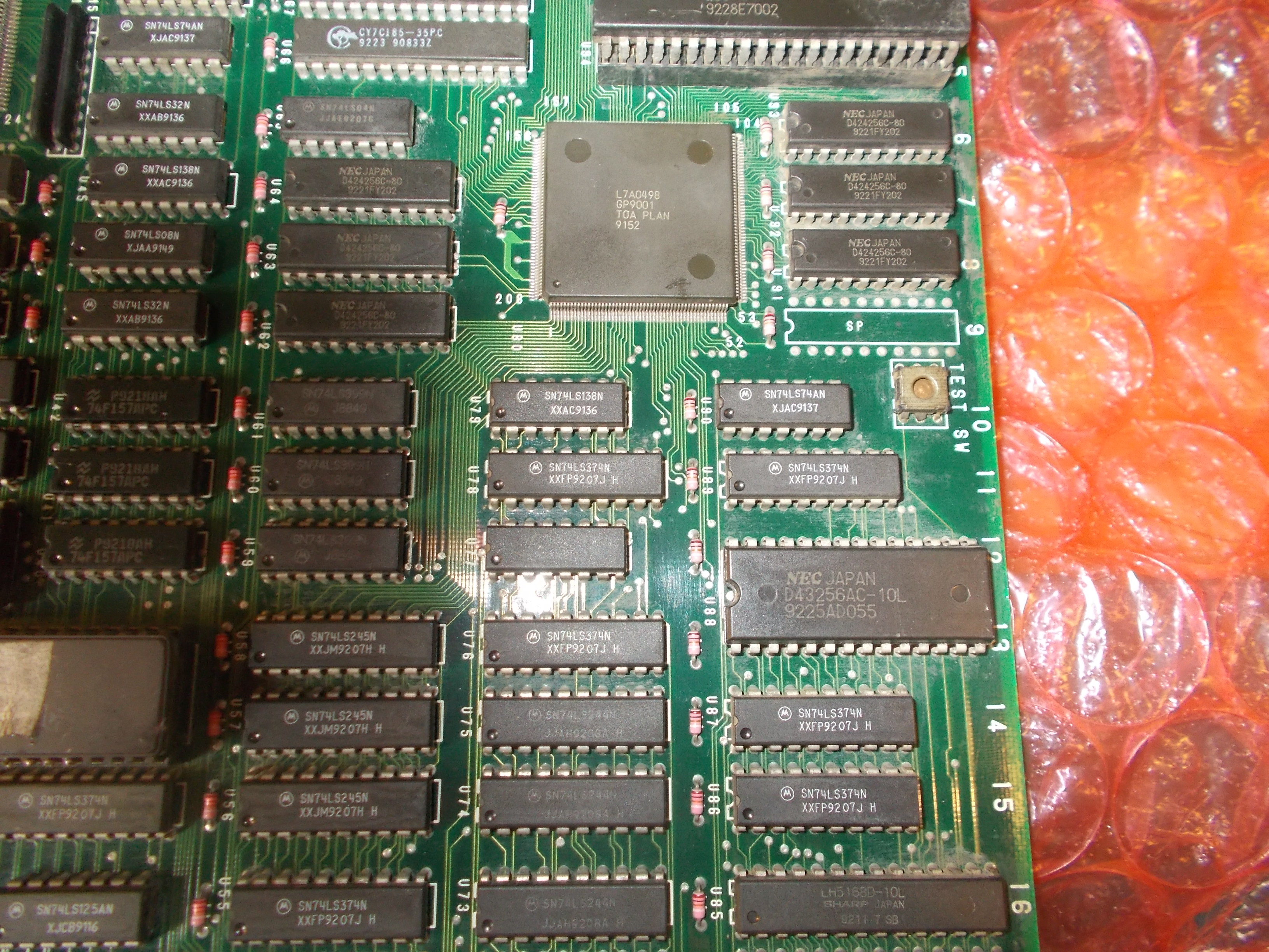
They are accessed by the QFP ASIC marked ‘GP9001’ which is the graphics controller of the system:
For first I did a visual inspection of it and found some pins not really firm (common issue on QFP with this fine pitch)
I reflowed them but this didn’t led to any improvement so I moved to check the VIDEO RAM ICs and found weak signal on data lines:
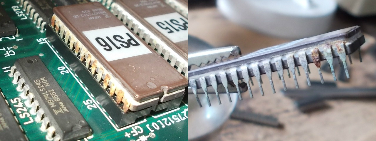
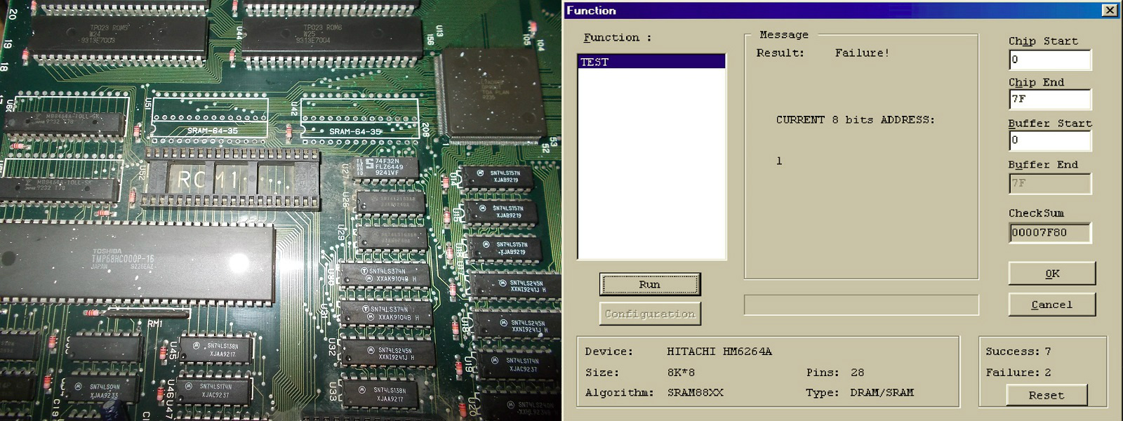
I pulled both RAMs, only the one @U42 failed the out-of-circuit testing:
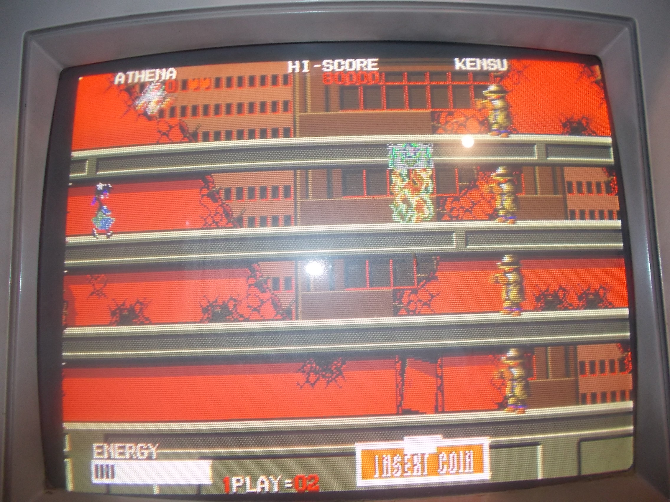
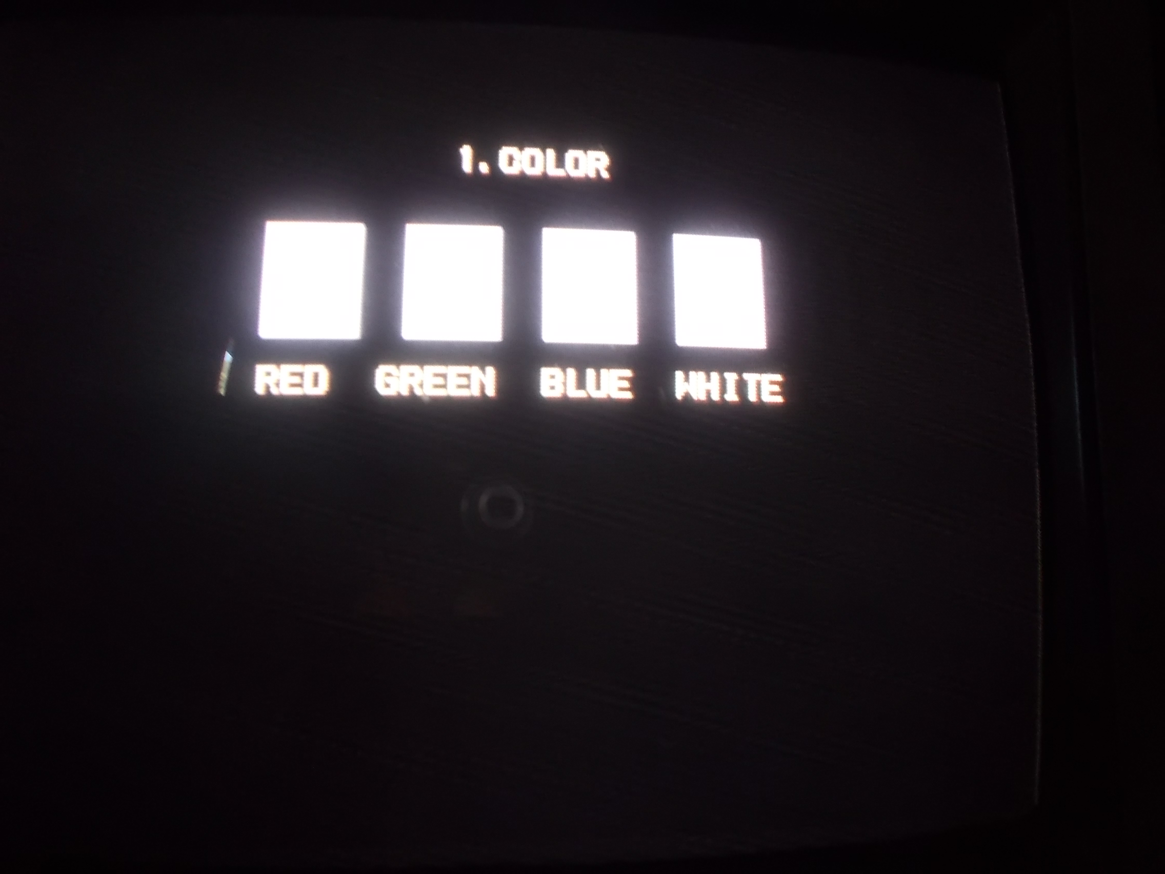
The board successfully booted into game now but the colors were wrong, they were “bleeding”:
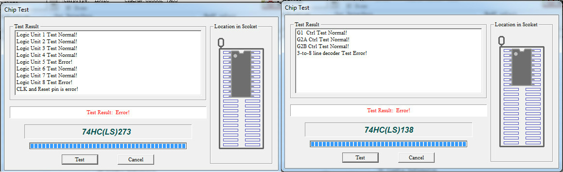
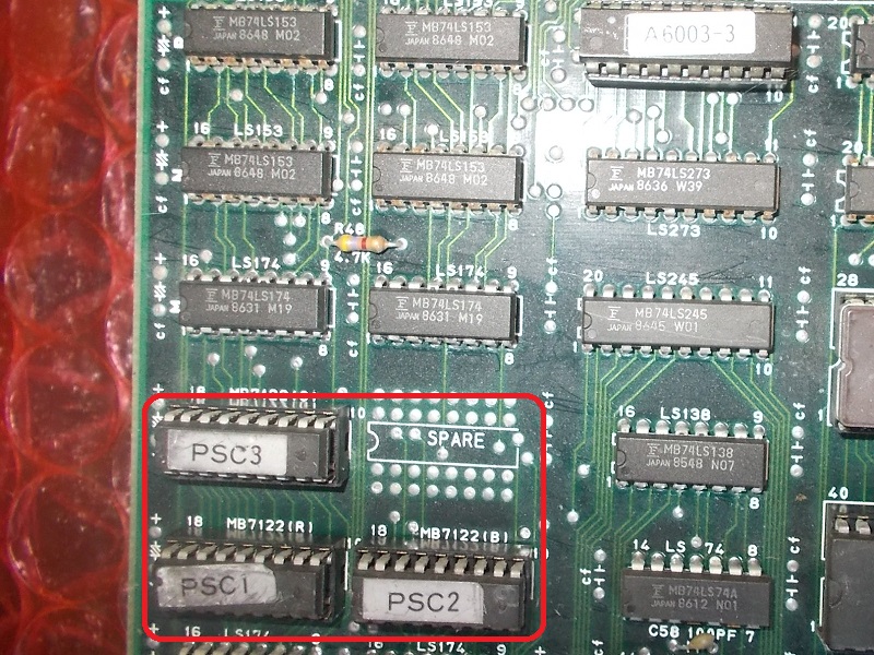
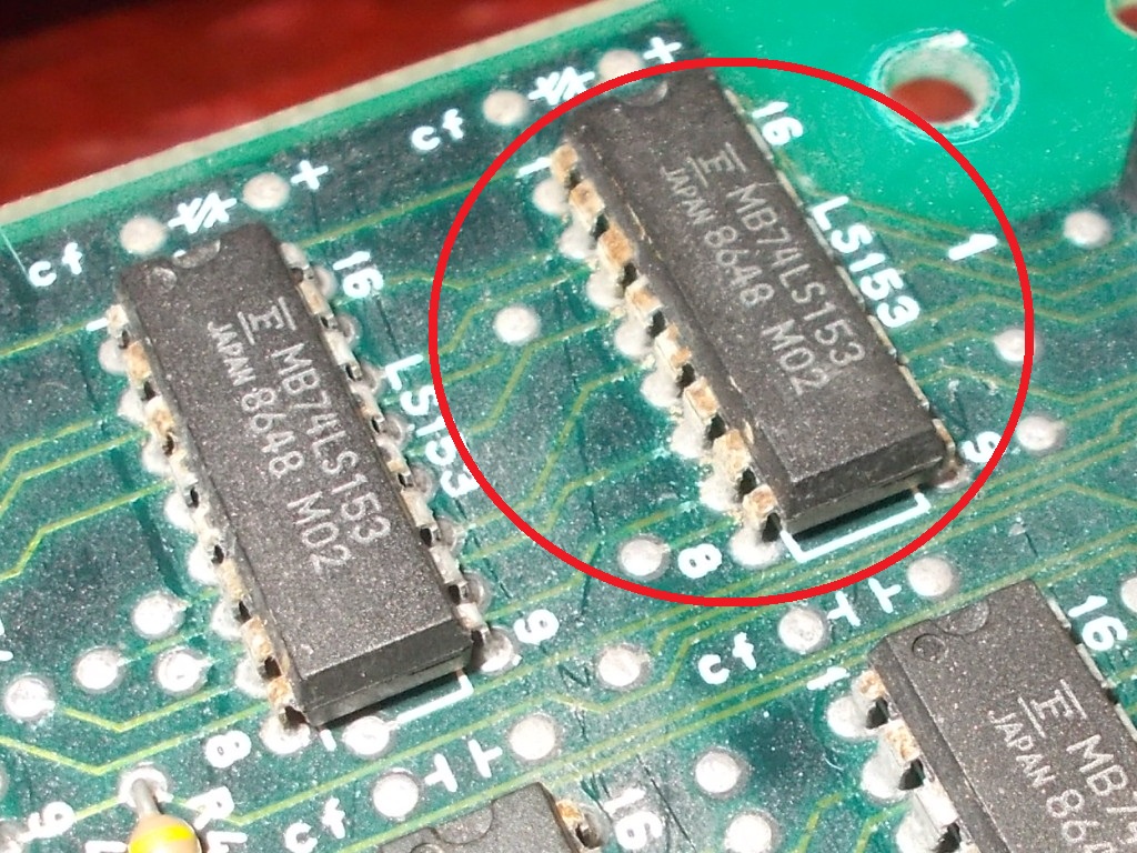
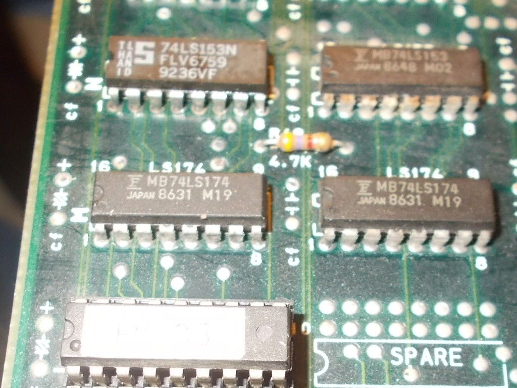
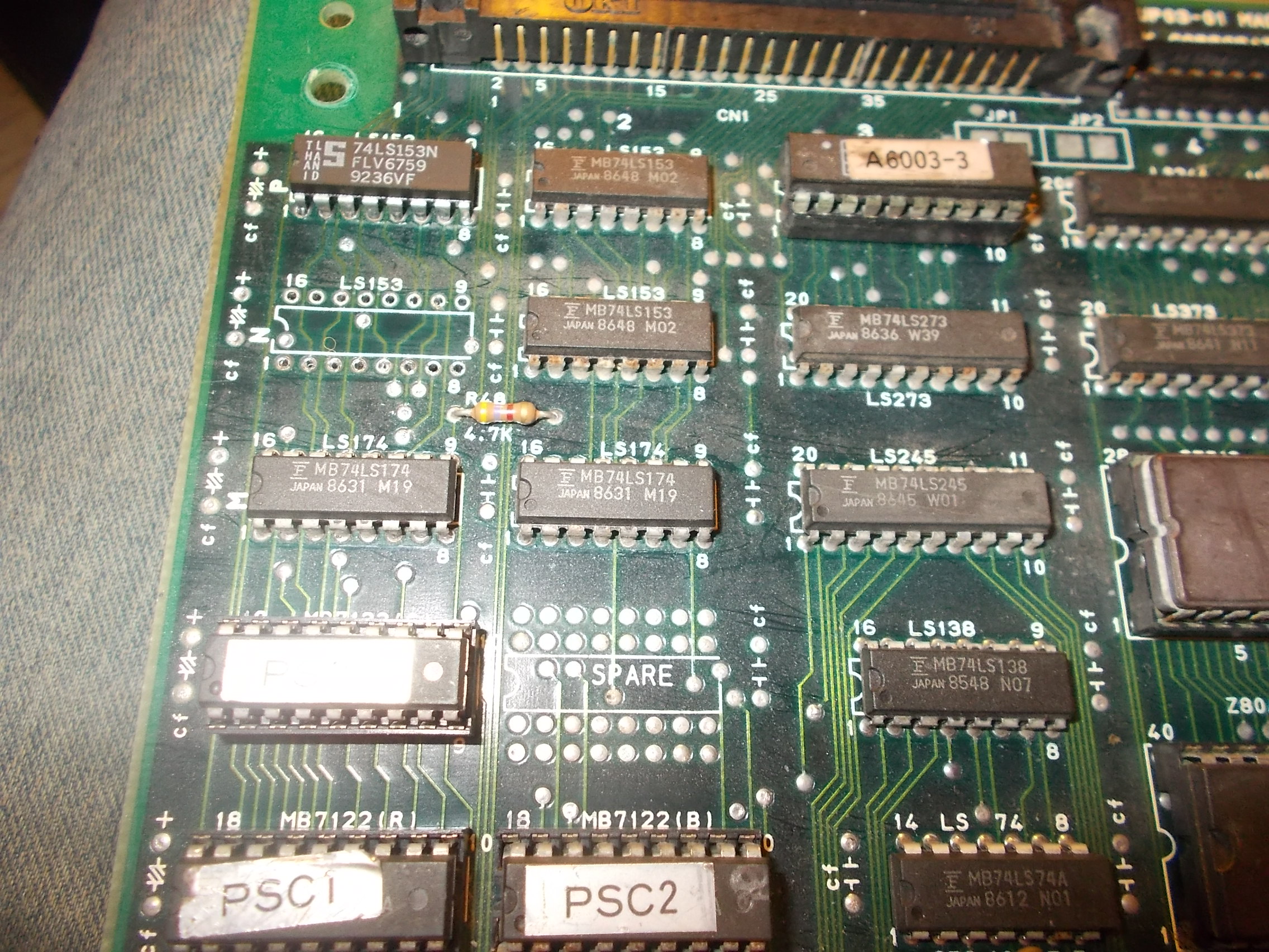
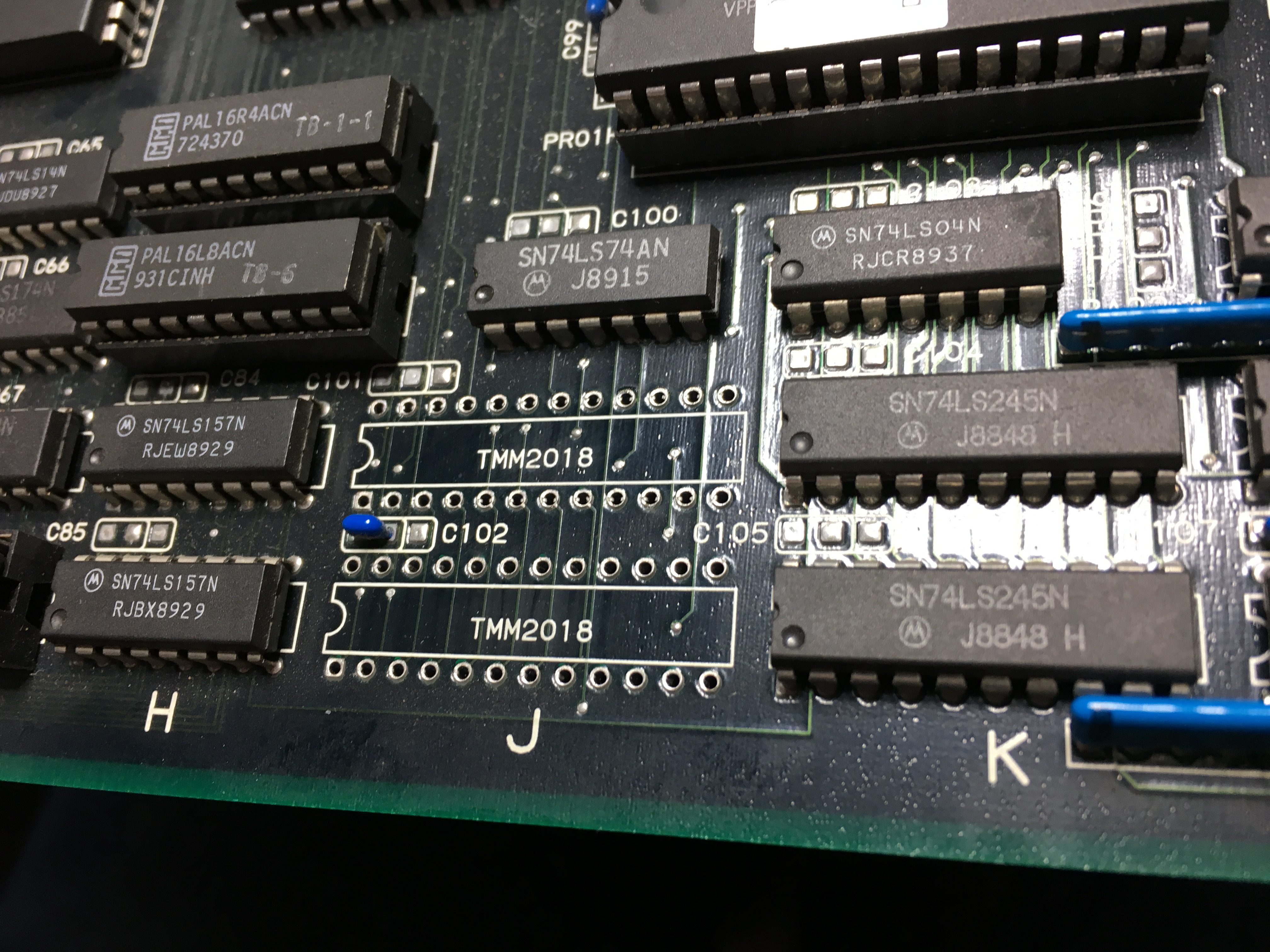
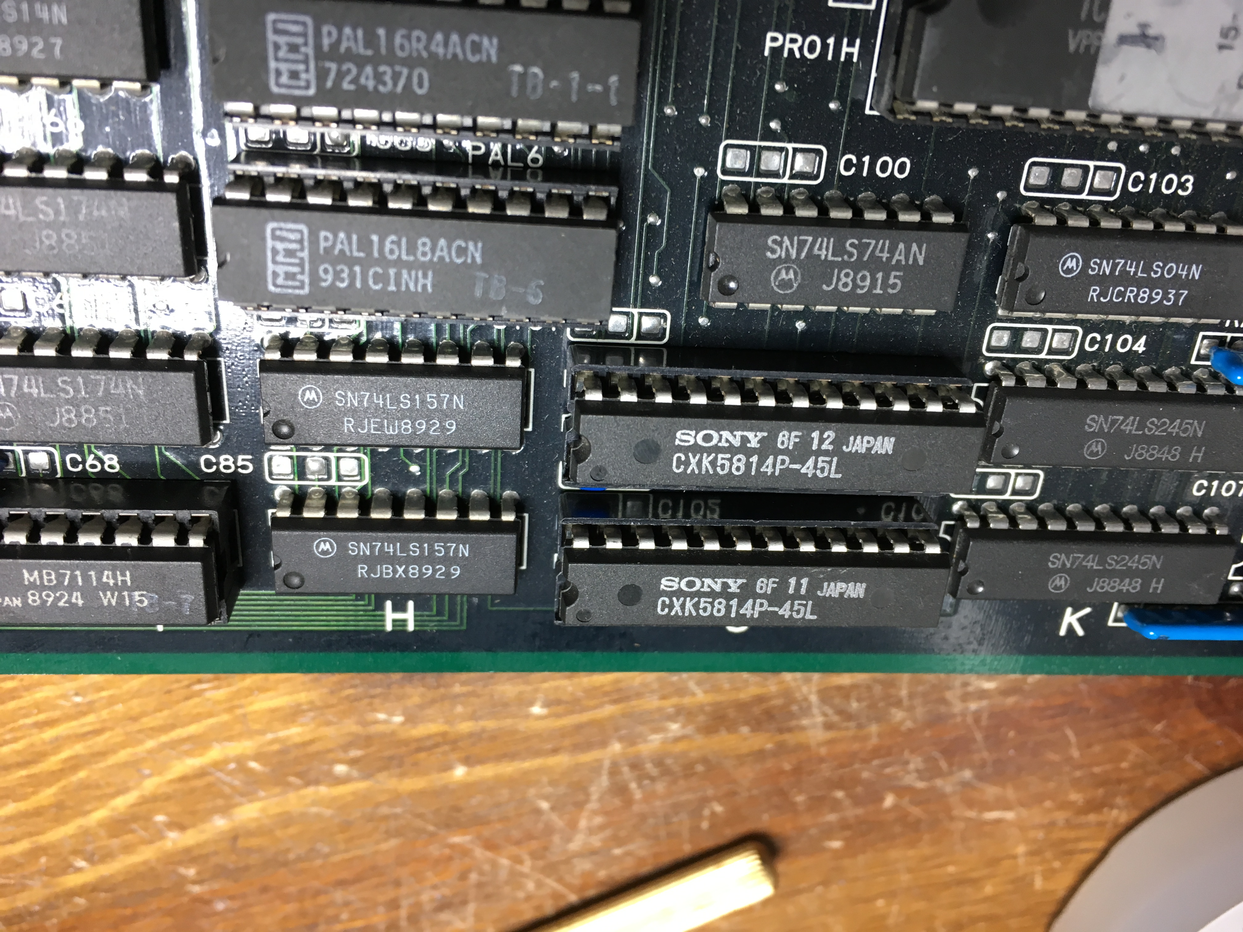
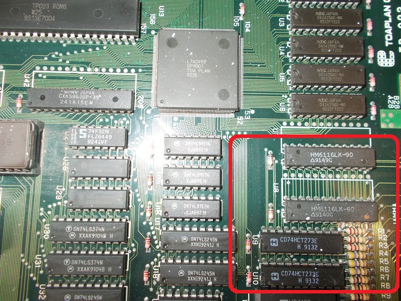
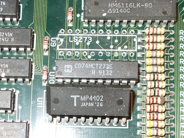
This is another common issue on this board so I knew where to look exactly.The data bits from the two 6116 (2K x 8-bit) palette SRAMs are latched by two 74HC273:
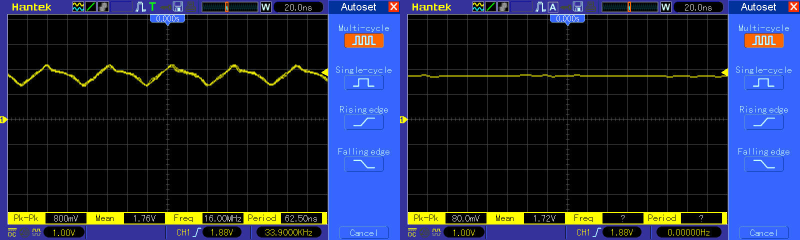
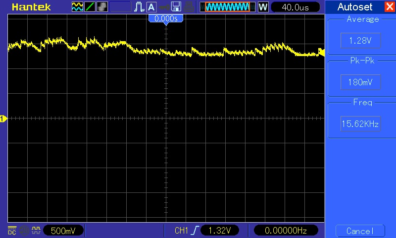
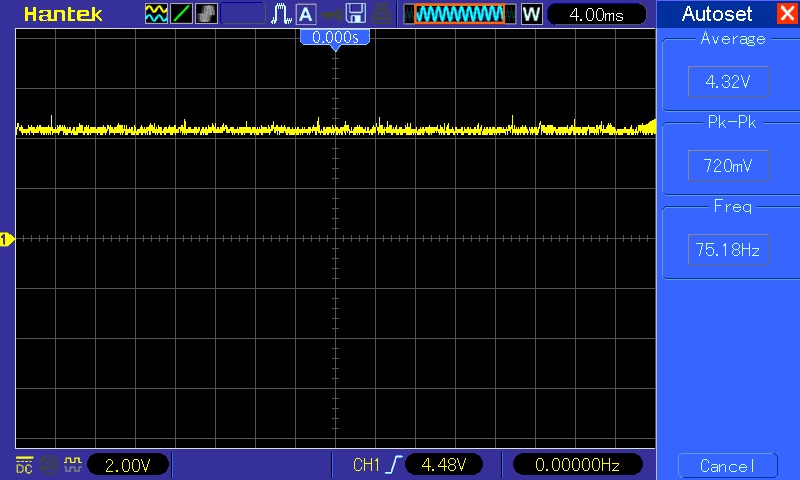
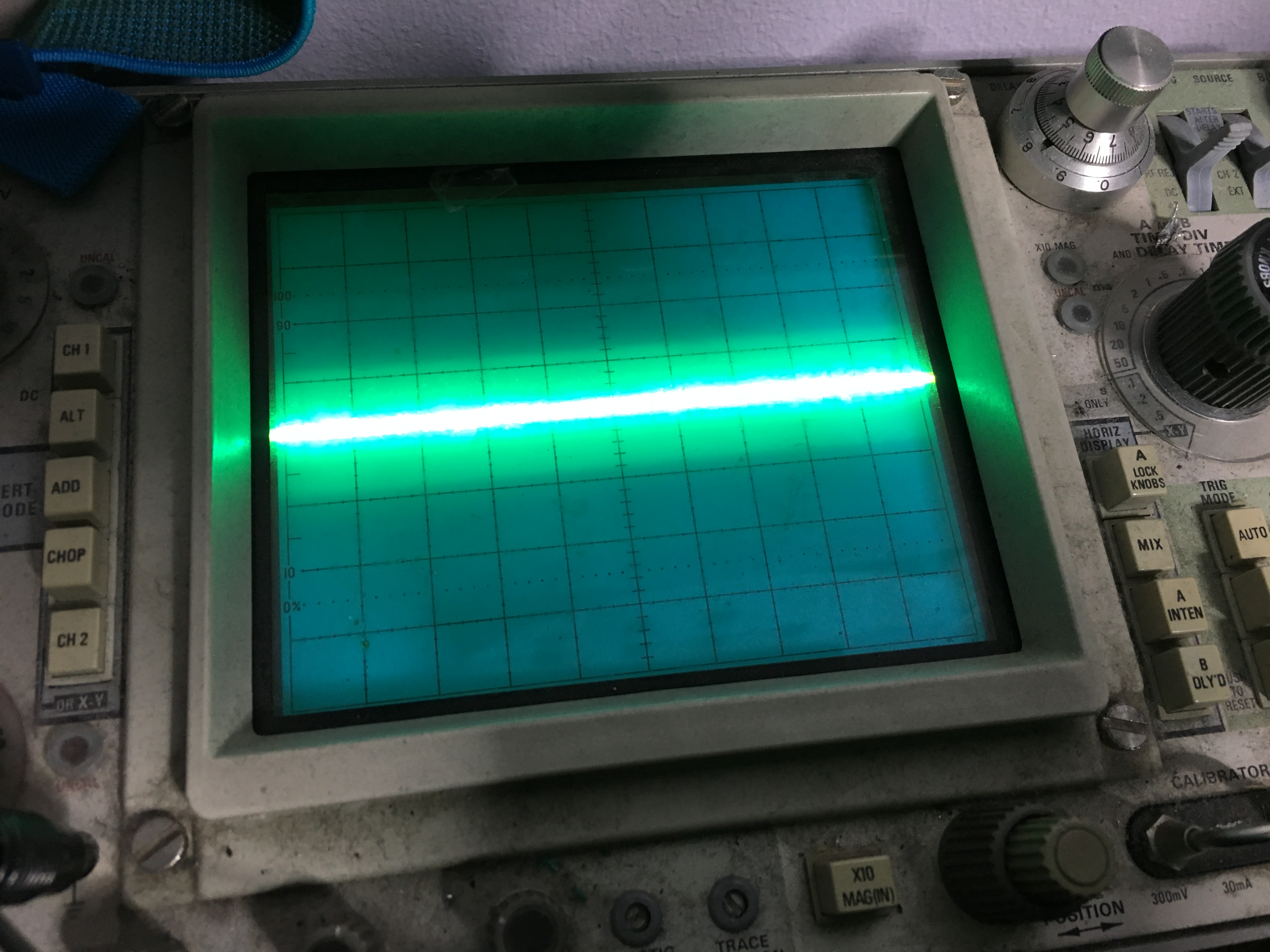
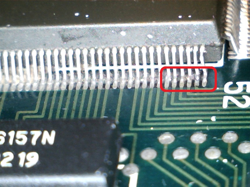
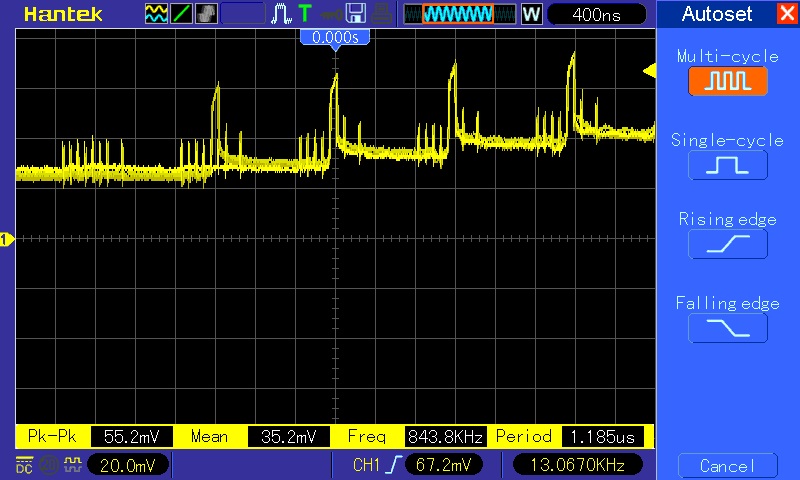
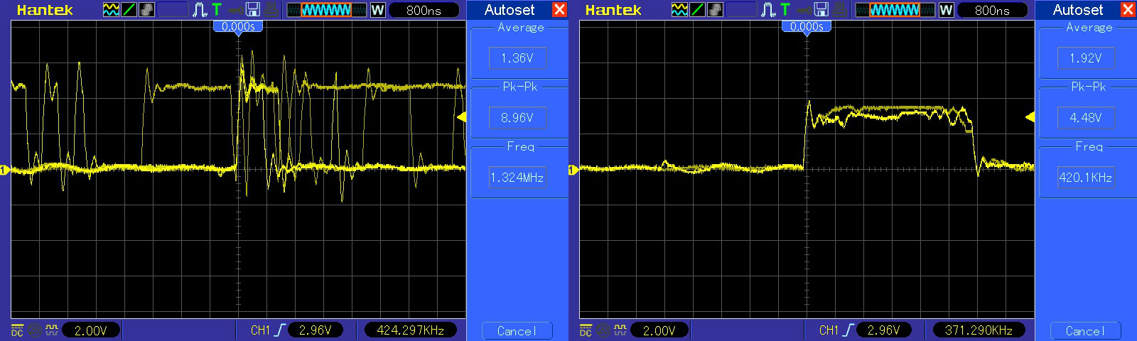
Probing with a scope the 74HC273 @U9 revealed weak signal on outputs (inputs on the left of the below snapshot, outputs on the right)
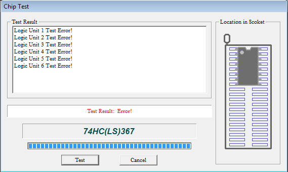
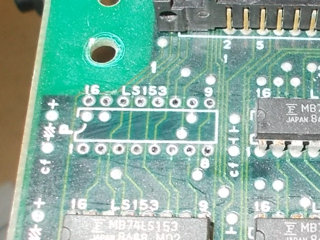
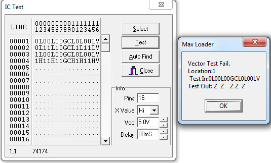
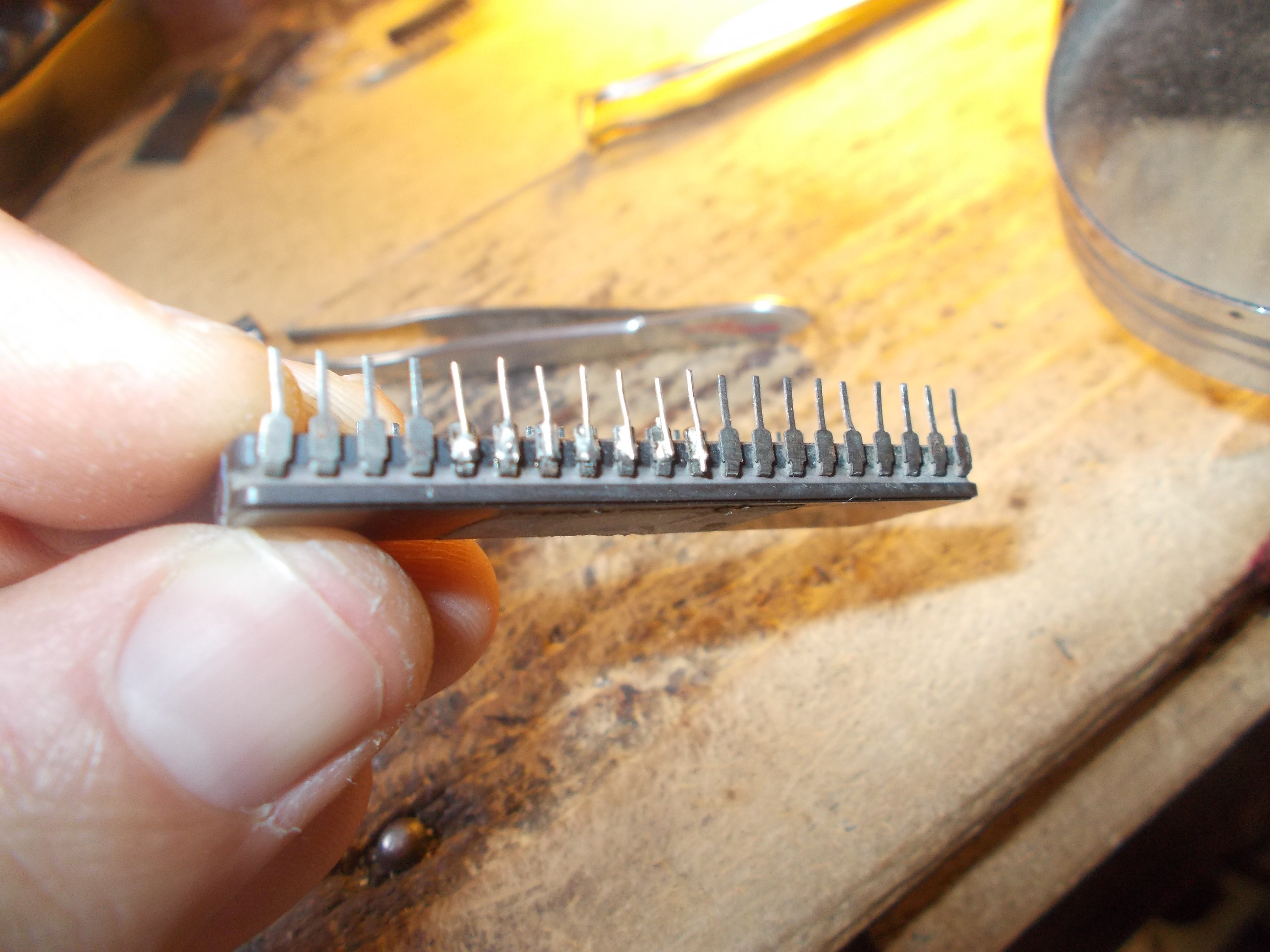
I pulled the IC:
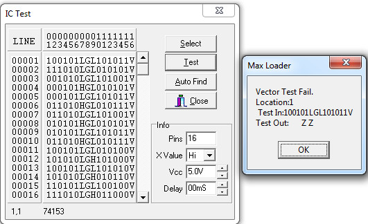
It actually passed the out-of-circuit testing on all my programmers so I think IC was not really bad but it had altered voltage thresholds.Anyway, I replaced it and this fixed the board completely.
Now the FixEight troubleshooting.
Board gave me a steady black screen.This board uses the GP9001 graphic controller too:
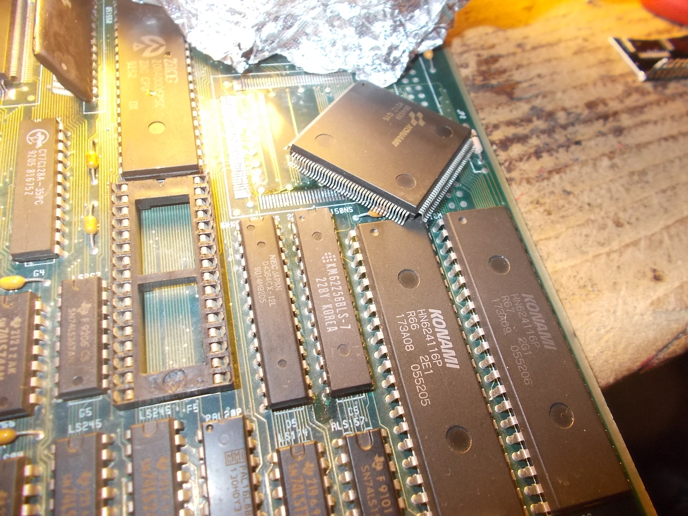
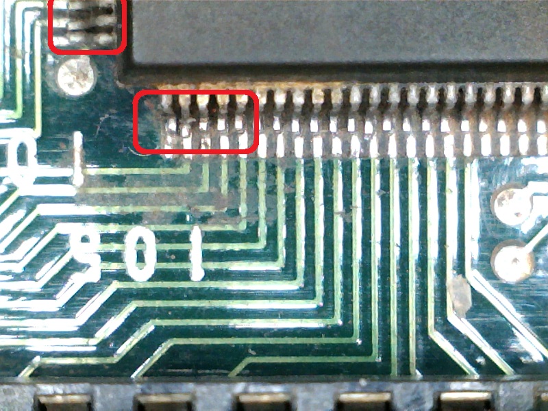
Found some lifted pins on it:
I reflowed them as well as replaced the main program code 4Mbit EPROM since it had some rebuilt pins that gave me trouble when dumping it:
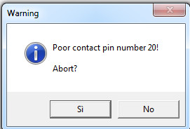
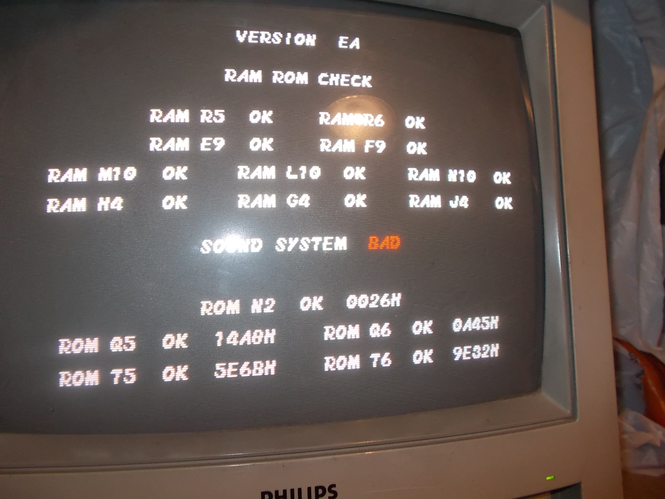
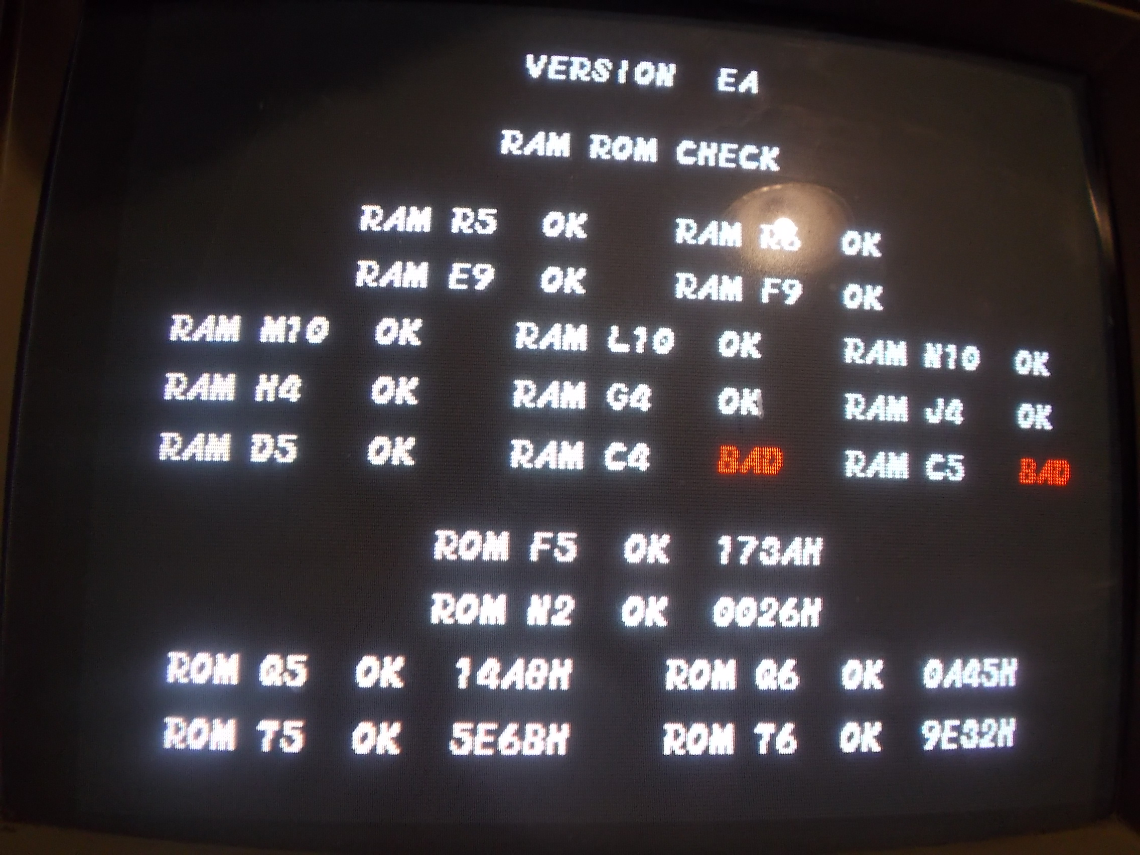
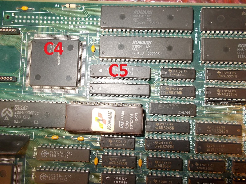
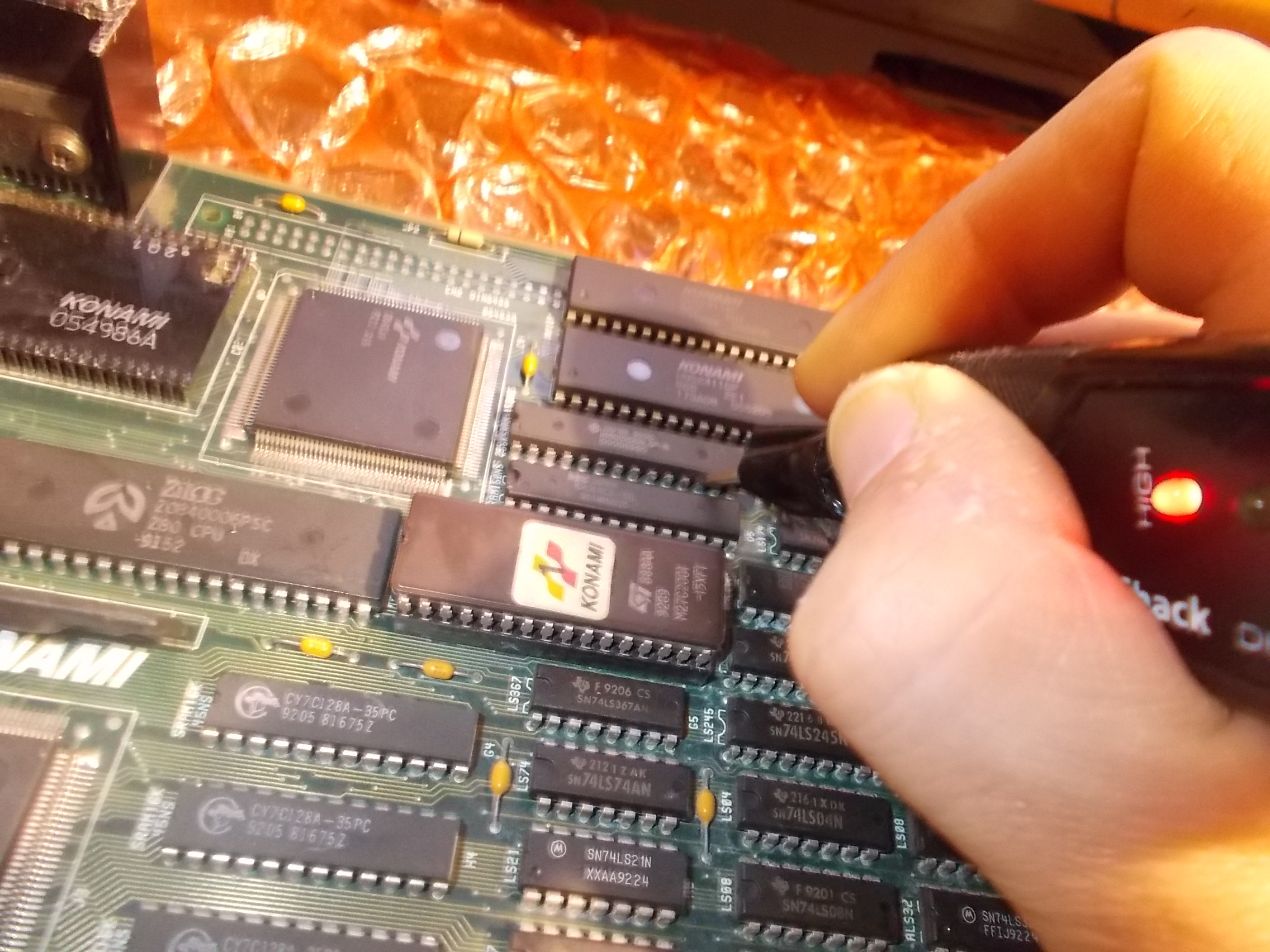
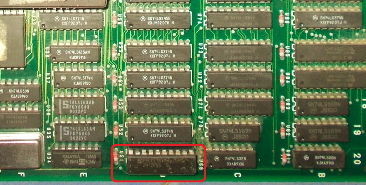
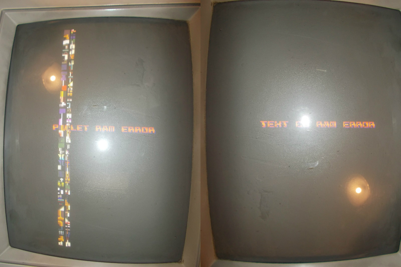
But still no boot.But I noticed that pressing the PAL16V8 @U51 :
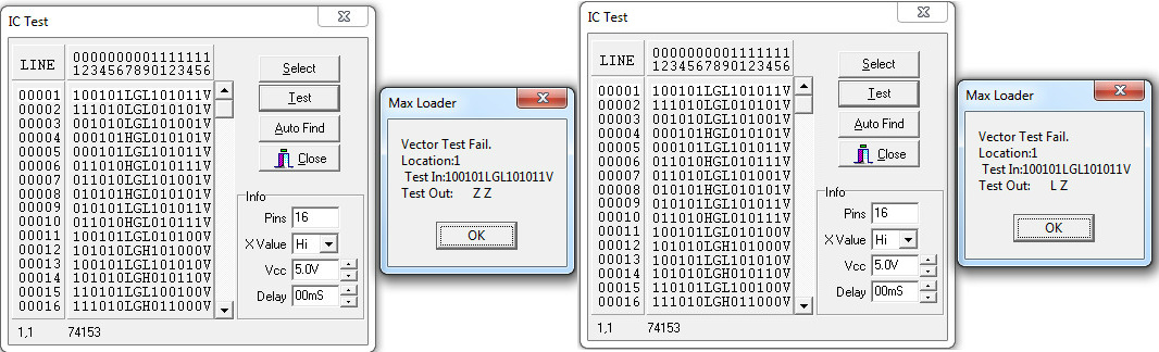
produced a couple of different RAM error messages on screen:
Solderside of the PAL socket had some dry joints:
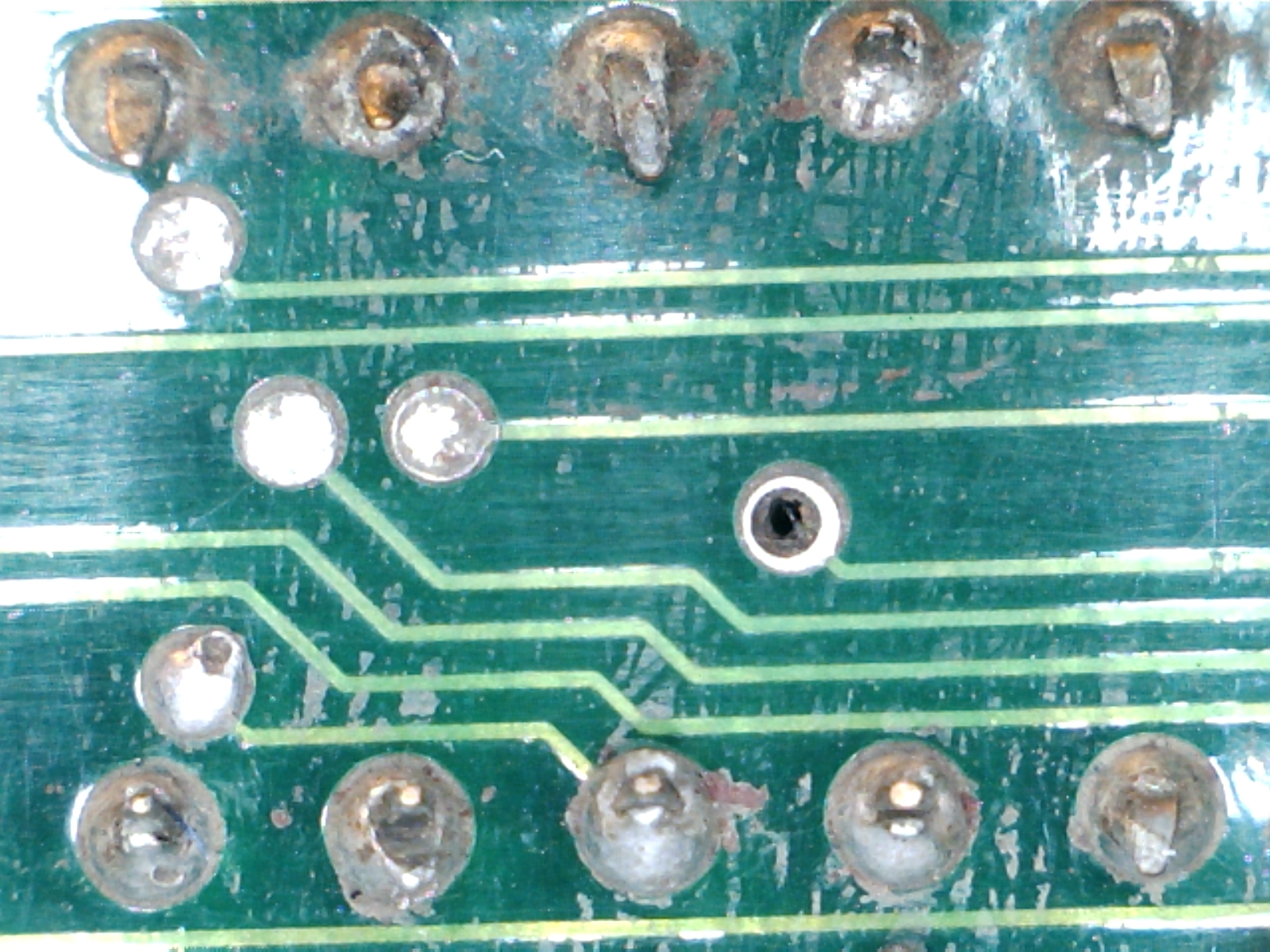
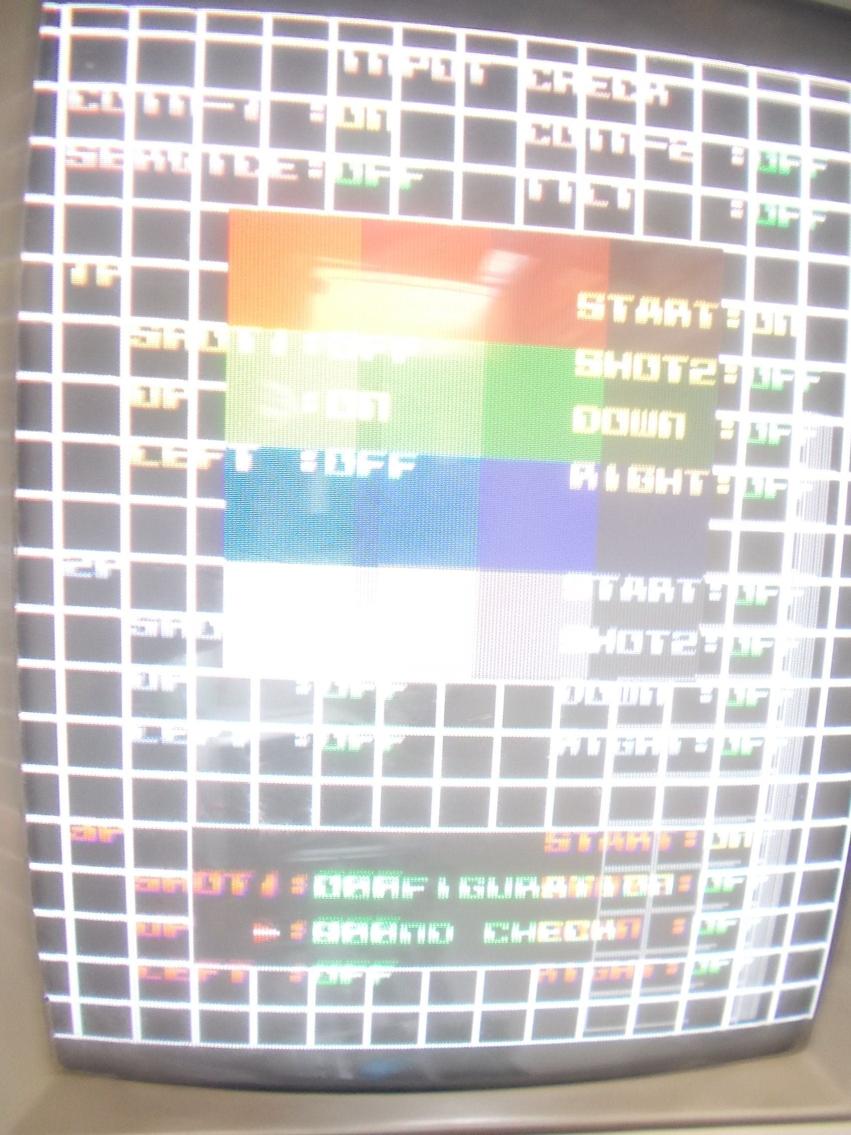
So I replaced it and finally the board initialized but it quickly went straight into SERVICE mode and then reset in an endless loop :
From a still image I noticed that some inputs were stuck in I/O check:
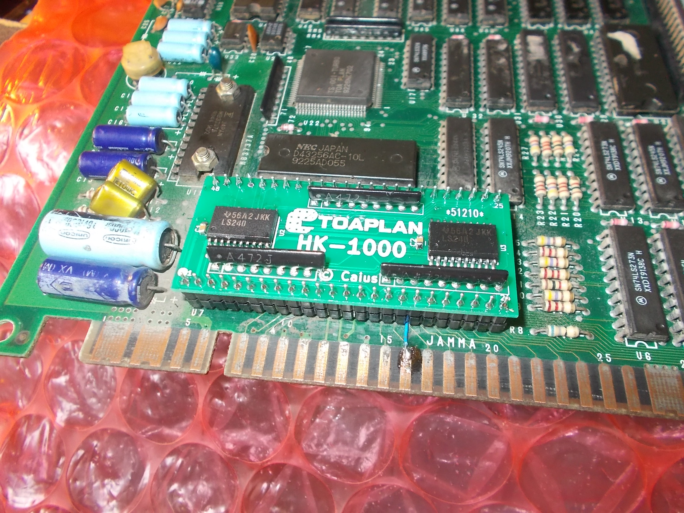
The inputs are handled by the custom ‘HK-1000’, you can find more info about it in a past article from mine:
On my PCB a replacement board had been used in place of the original part:
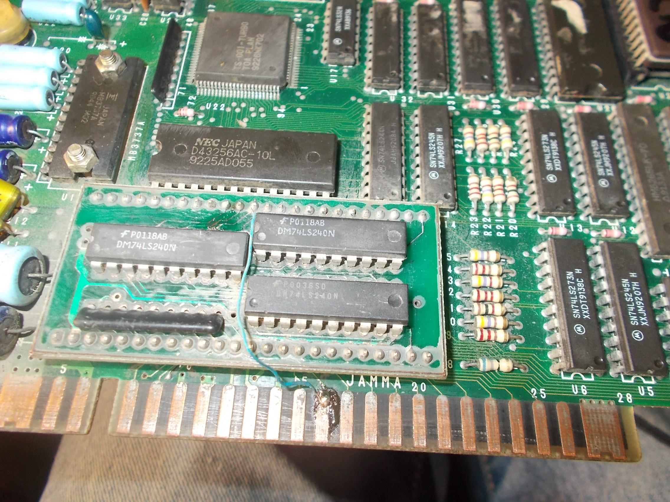
Some inputs of a 74LS240 on this replacement board were shorted to ground.Instead of repairing it, I opted for a reproduction of mine (the blue jumper wire was already there to patch a trace previoulsy broken during the removal of the original ‘HK-1000’)
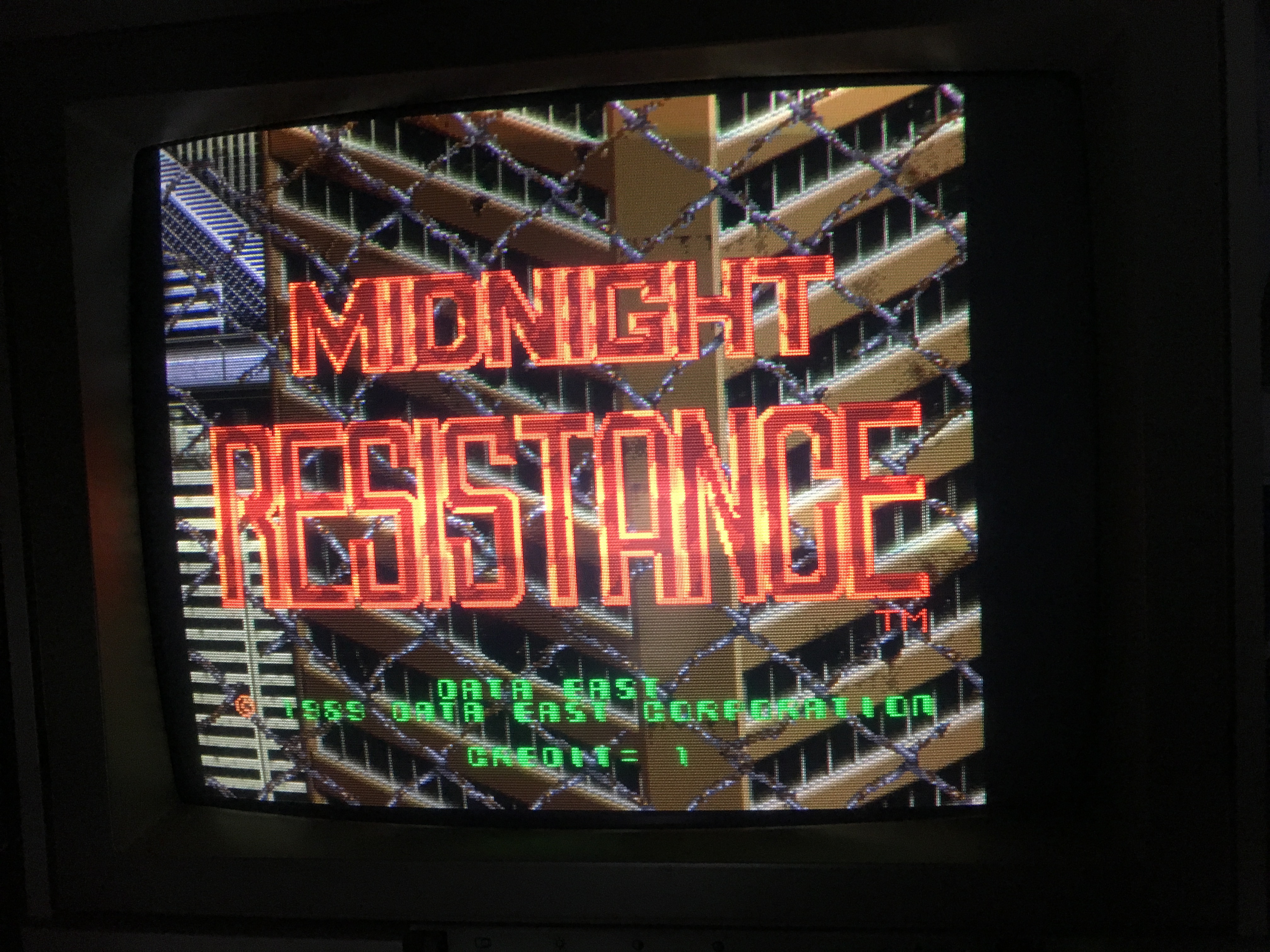
Finally the board booted into game with no further issues.Toplan double repair log accomplished.