Got this game from a friend who took out the board out of a rusty cabinet.
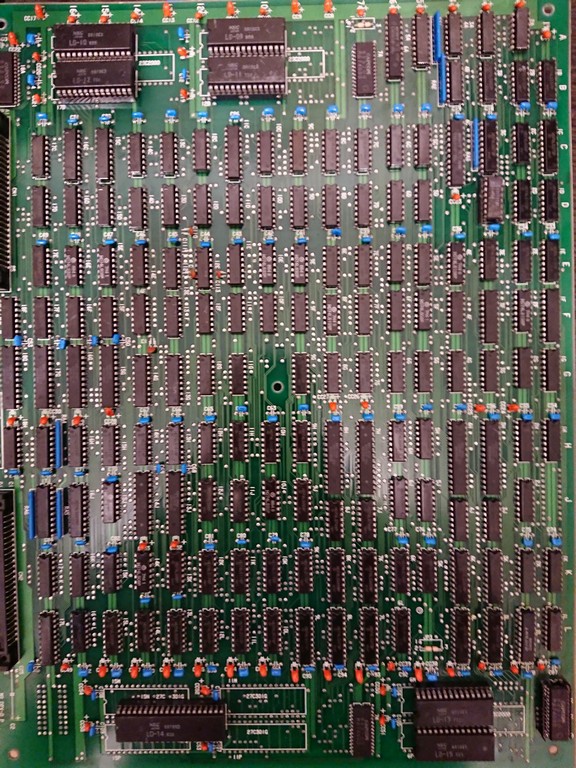
The game needed badly a clean, so I dismounted everything before attempting to turn it on and washed everything carefully.
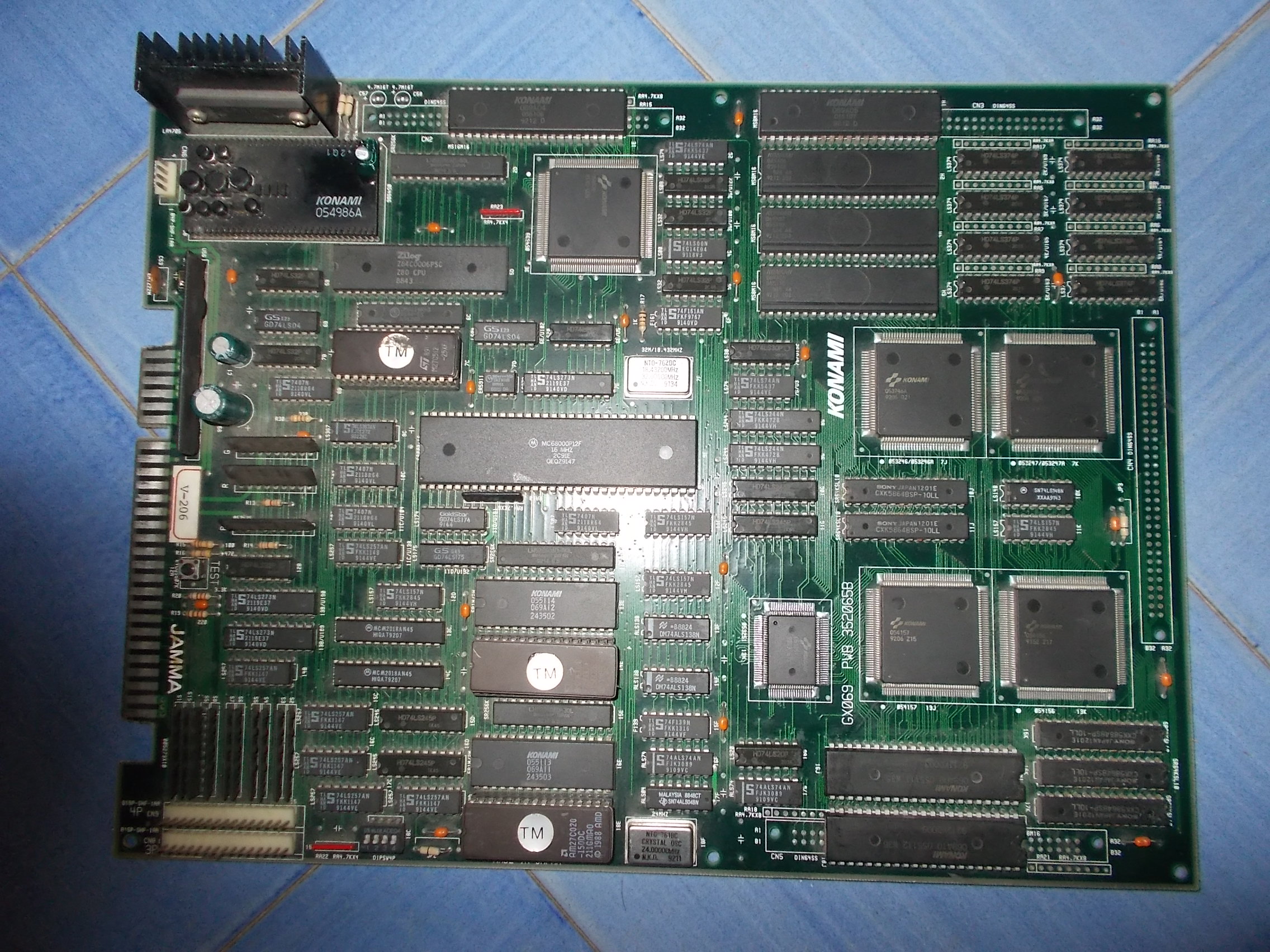
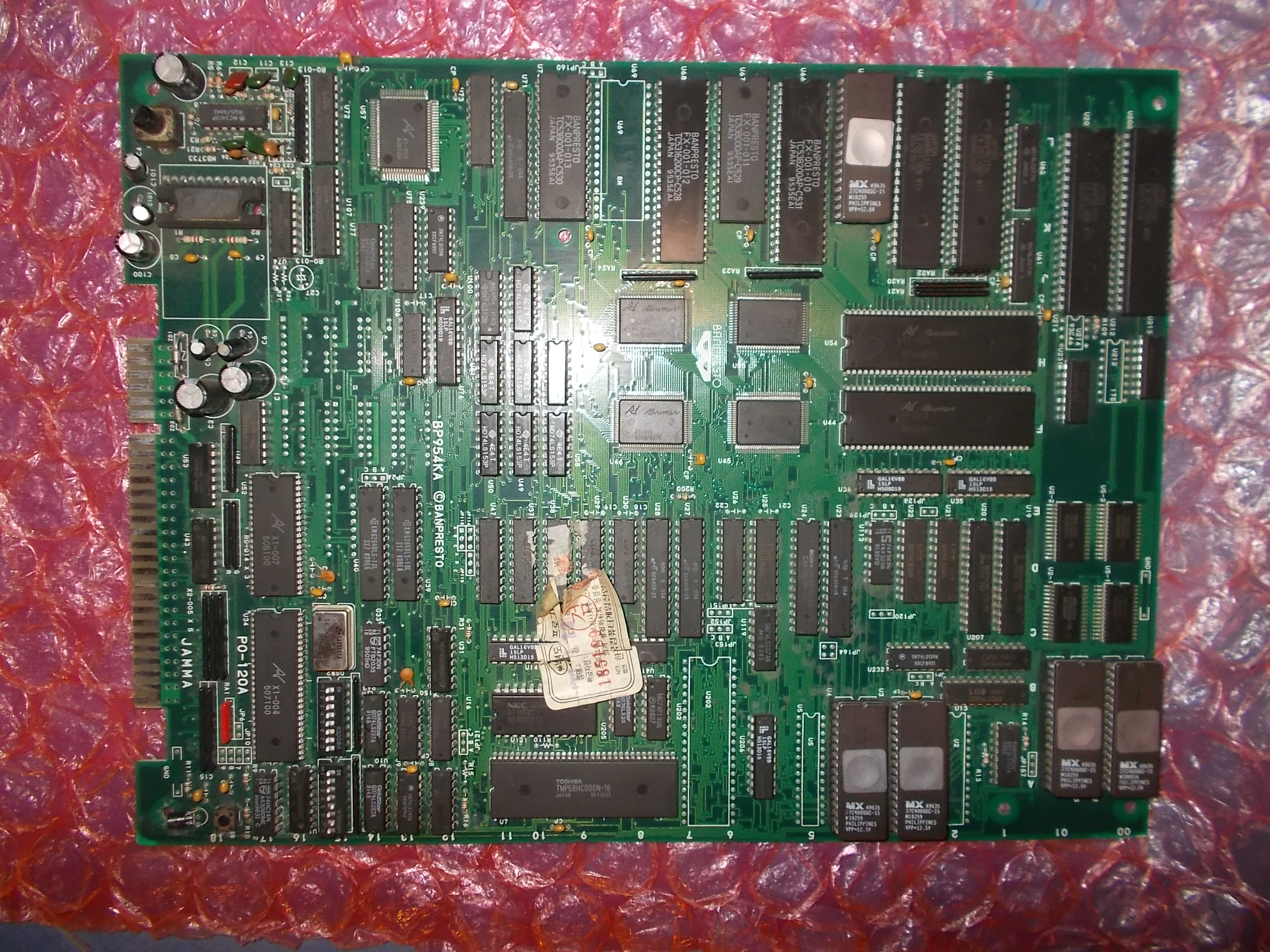
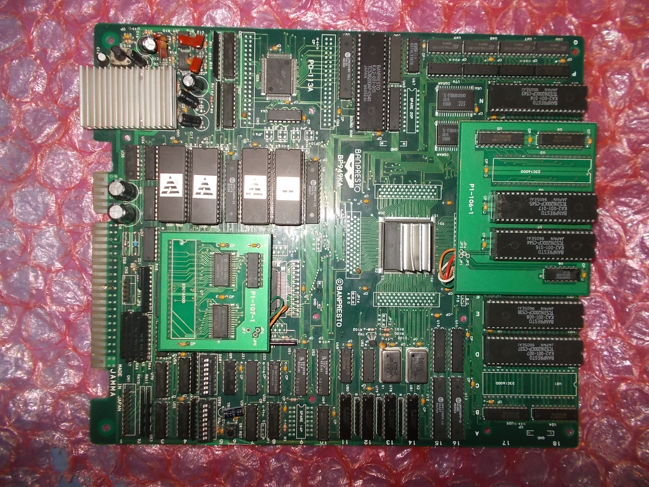
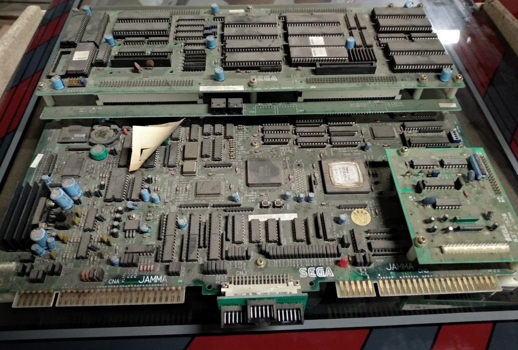
The game has two jamma connectors for player 1 ( Monitor A,left connector looking at the above picture) and player 2 ( Monitor B, right connector looking at the above picture). The connectors share same power lines, so you can connect wherever you want to play as P1 or P2.
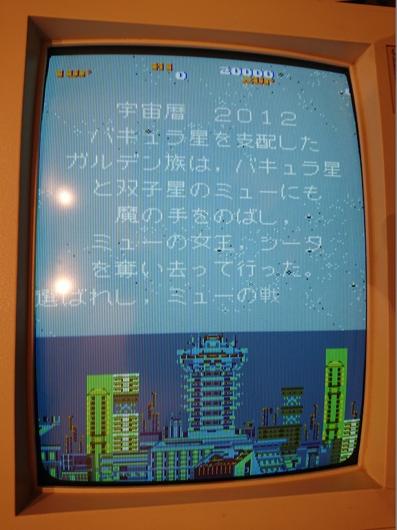
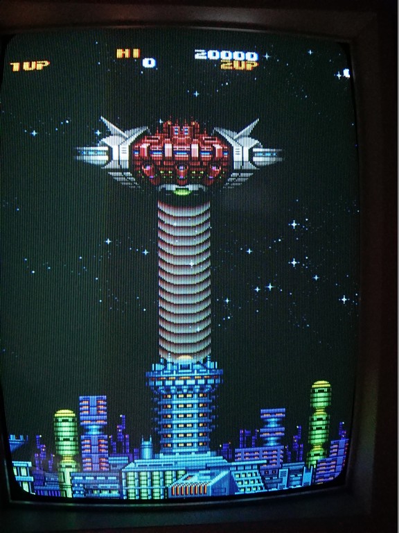
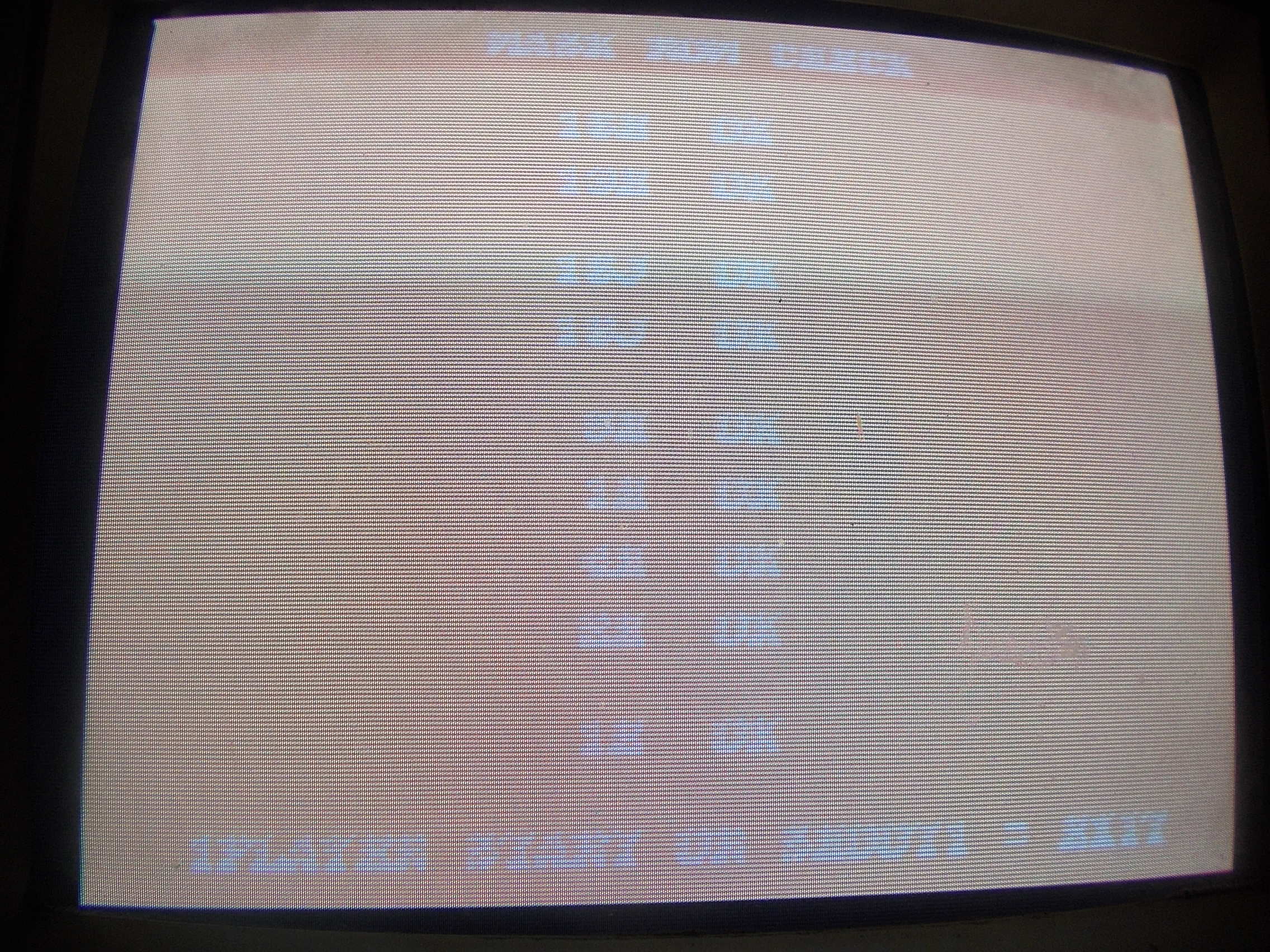
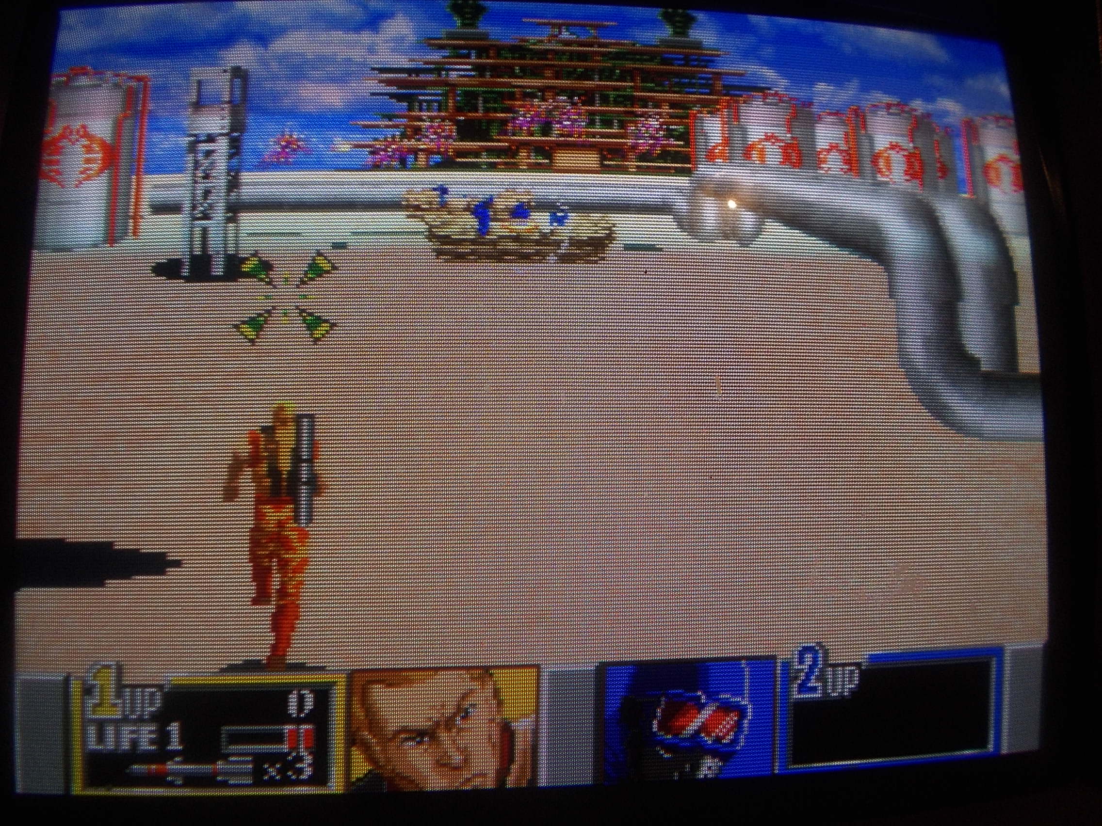
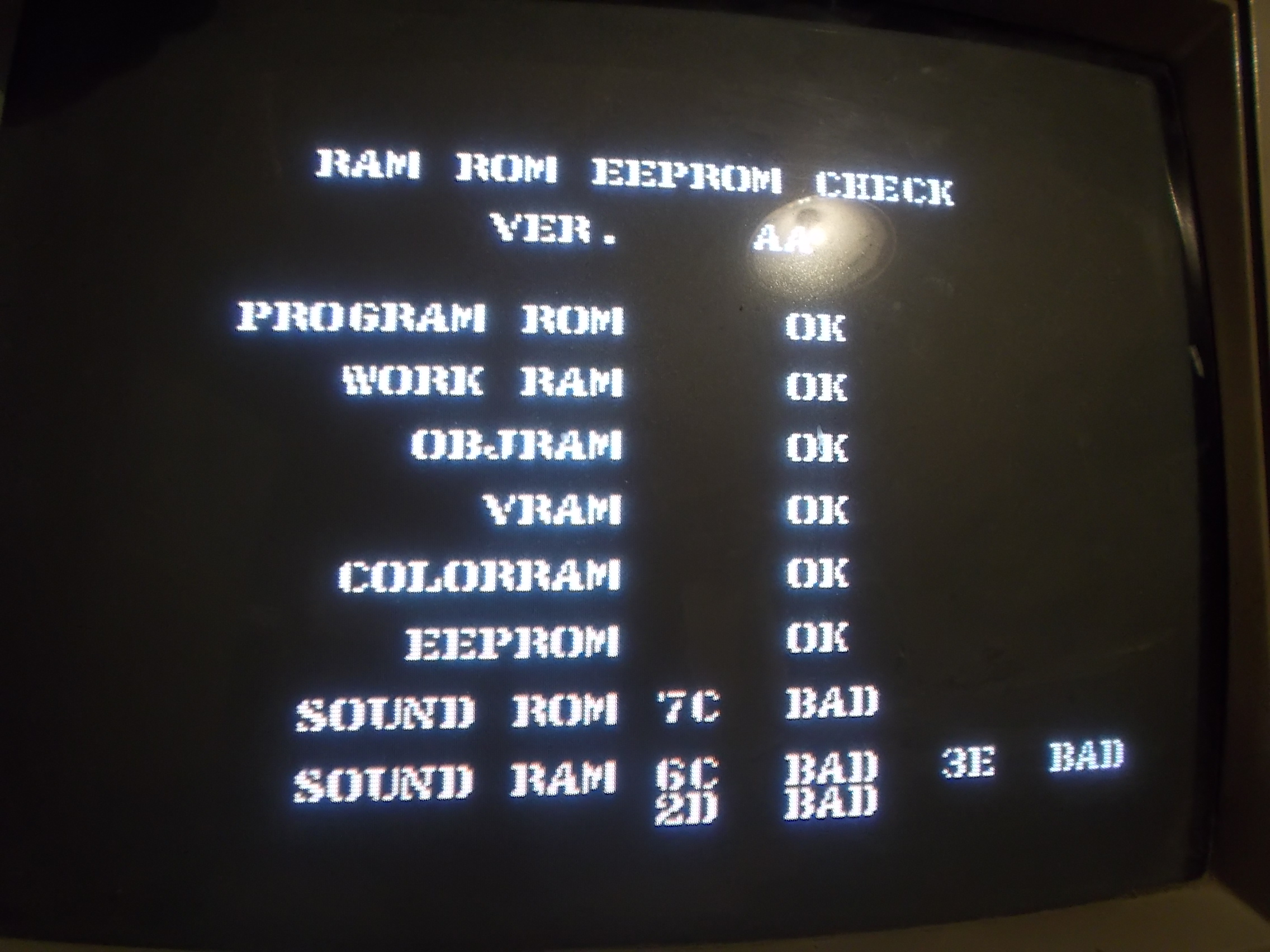
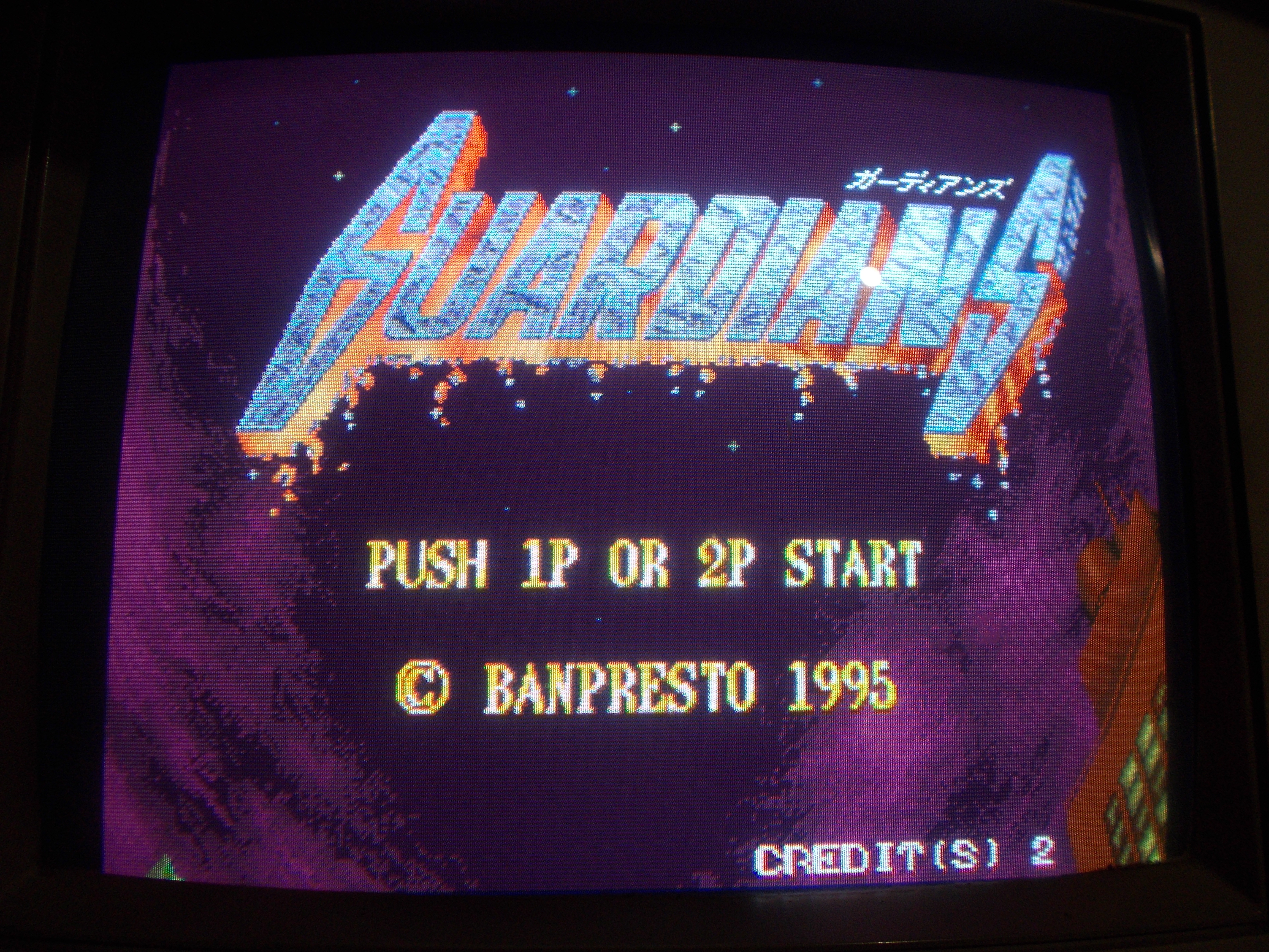
Unfortunately board was not working correctly, it showed from a brief moment a garbled text about network connection and then nothing happened.
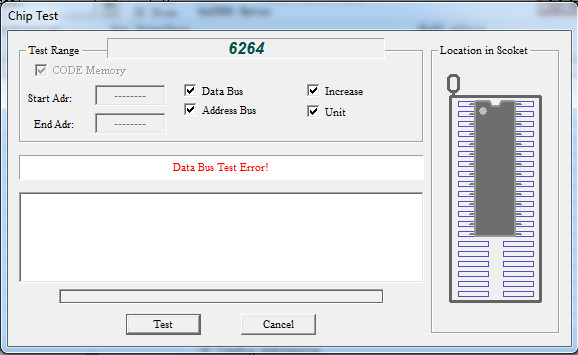
I decided to start dumping the program maskroms and found immediately one branded SEGA MPR-15539 which had some internal connection problems.
The other one , same type and capacity was dumped good.
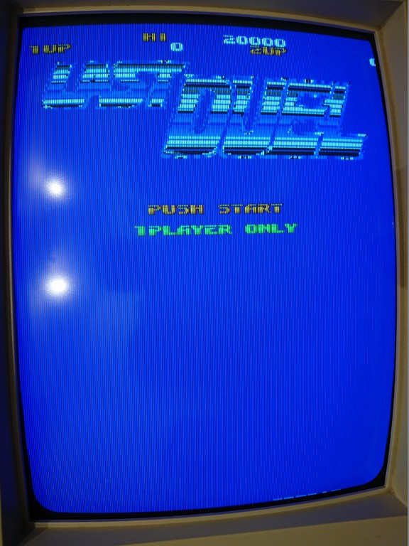
After burning a new program rom on a 27c400 ( 4mbit maskrom pinout eprom), game booted perfectly although without any sound.
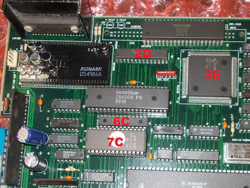
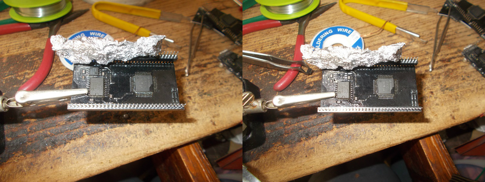
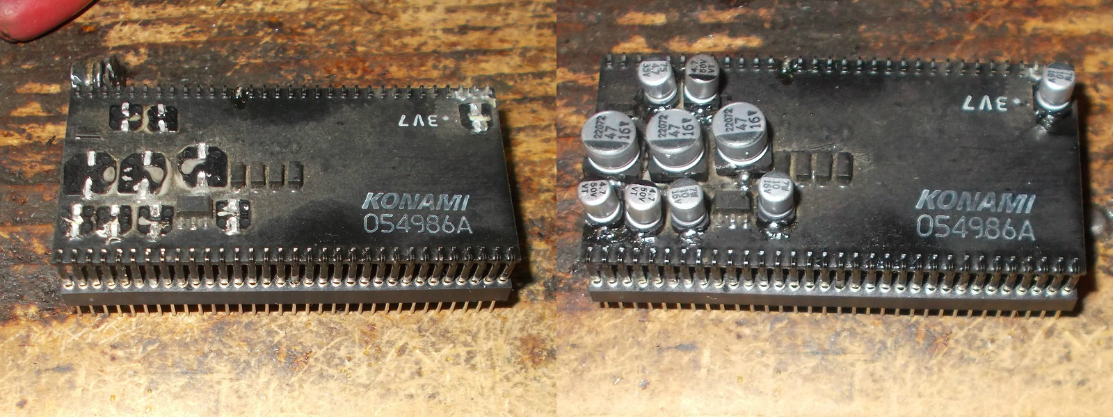
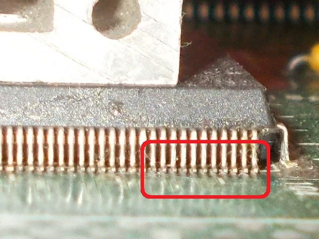
There was not even a noise coming from amplifier so I decided to desolder it and found immediately the problem
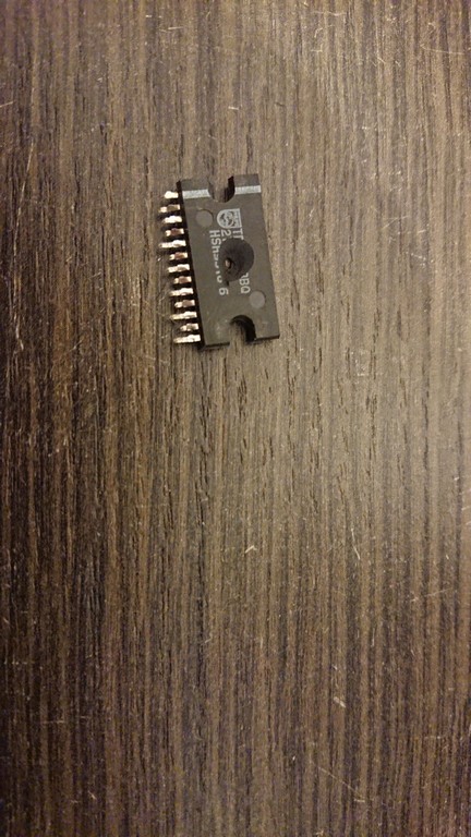
The amplifier was litterally blown
From Mame source I could get the right one to order, a TDA1518AQ, replaced it and finally the game had sound.
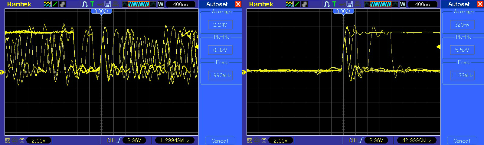
Unfortunately some tracks sounded bad with wrong samples.
There were other SEGA branded maskroms used as PCM samples, I read both of them ( 16mbit maskroms) and one of them , IC1, had A16 internally broken.
After buring a new 27c160 eprom with IC1 data, game sounded perfectly again.
No other problems were found
I will share the pinout of the board to play it on a different cabinet than the original one with a filter board ( the manual has only the schematics of the filter board unfortunately).
Game is Jamma as stated, so all power, video and audio pins are the same.
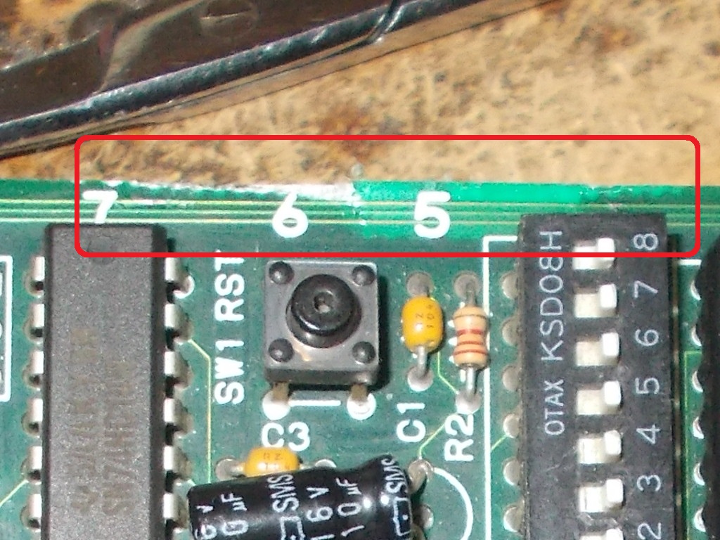
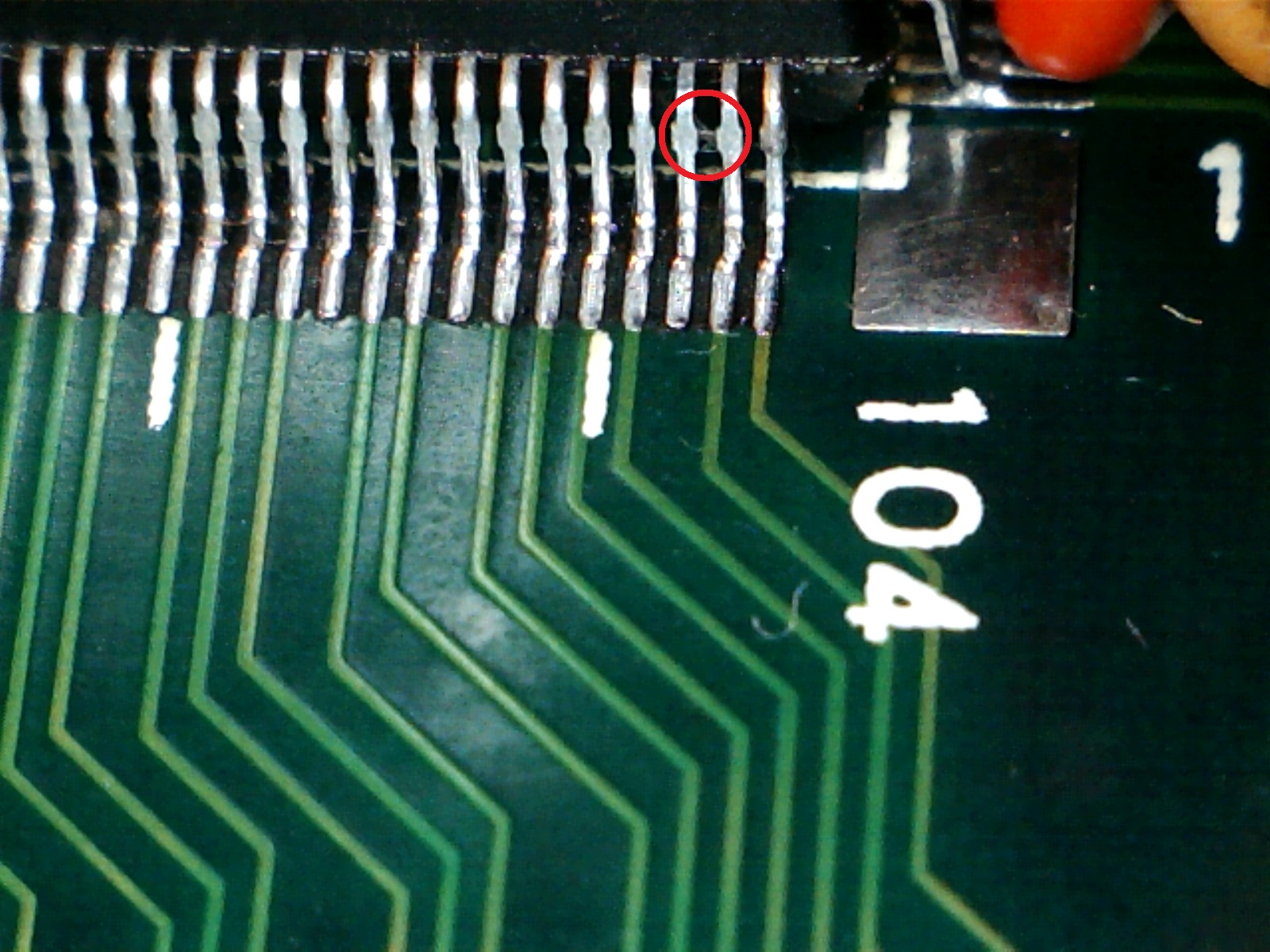
Board is using the following digital pins: on component side pin 22 is for shift up and pin 22 for shift down. On solder side, pin 22 is to select DJ Music or radio, pin 22 and pin 23 to move forward or backward the selection of musics. This is valid for both P1 and P2 connectors
There is an AMP connector in the middle used to drive lamps but I haven’t yet figured out the pinout and to me is not very interesting.
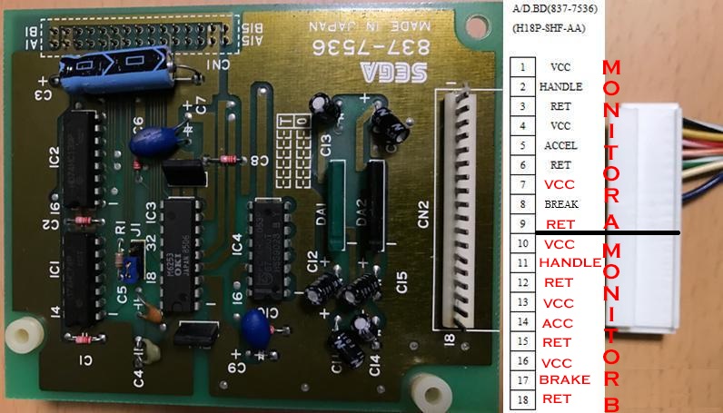
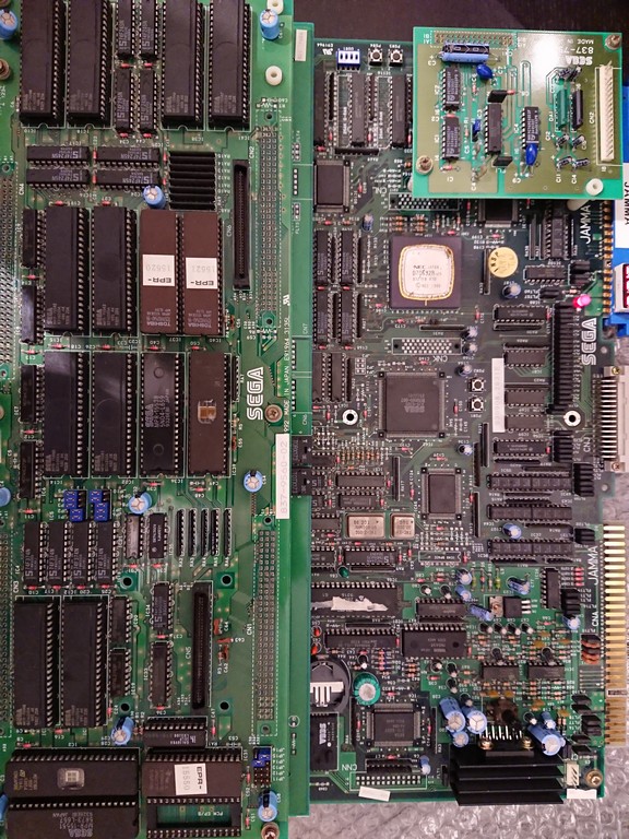
The most interesting part is the analogue controls which is handled but the daughter board 837-7636 which is in common with all Sega System 32 driving games.
I found a partial pinout on a japanese website and decided to expand it with Outrunner pinout