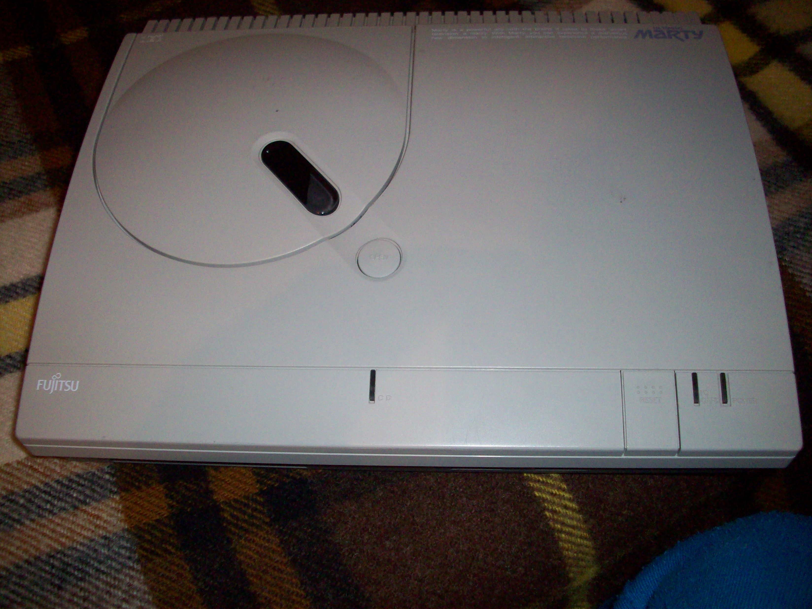
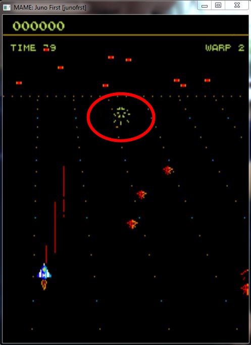
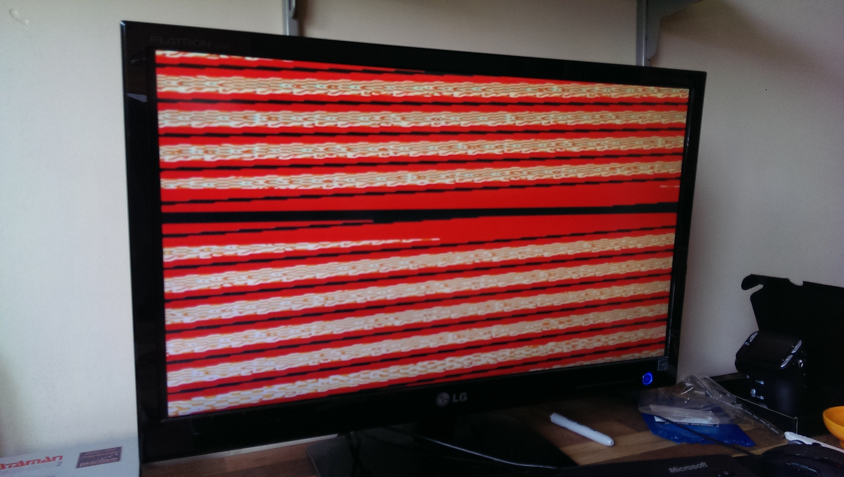
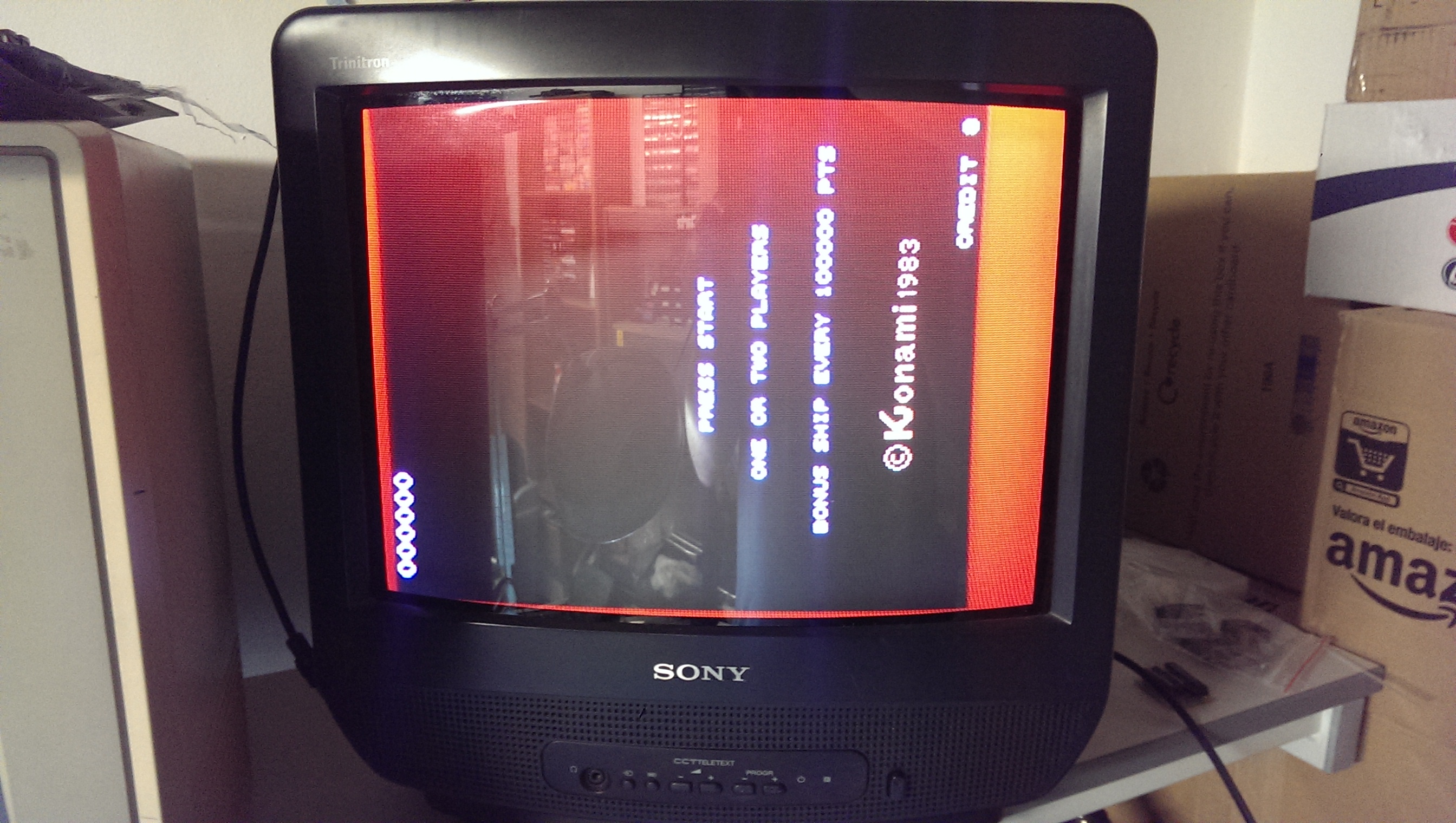
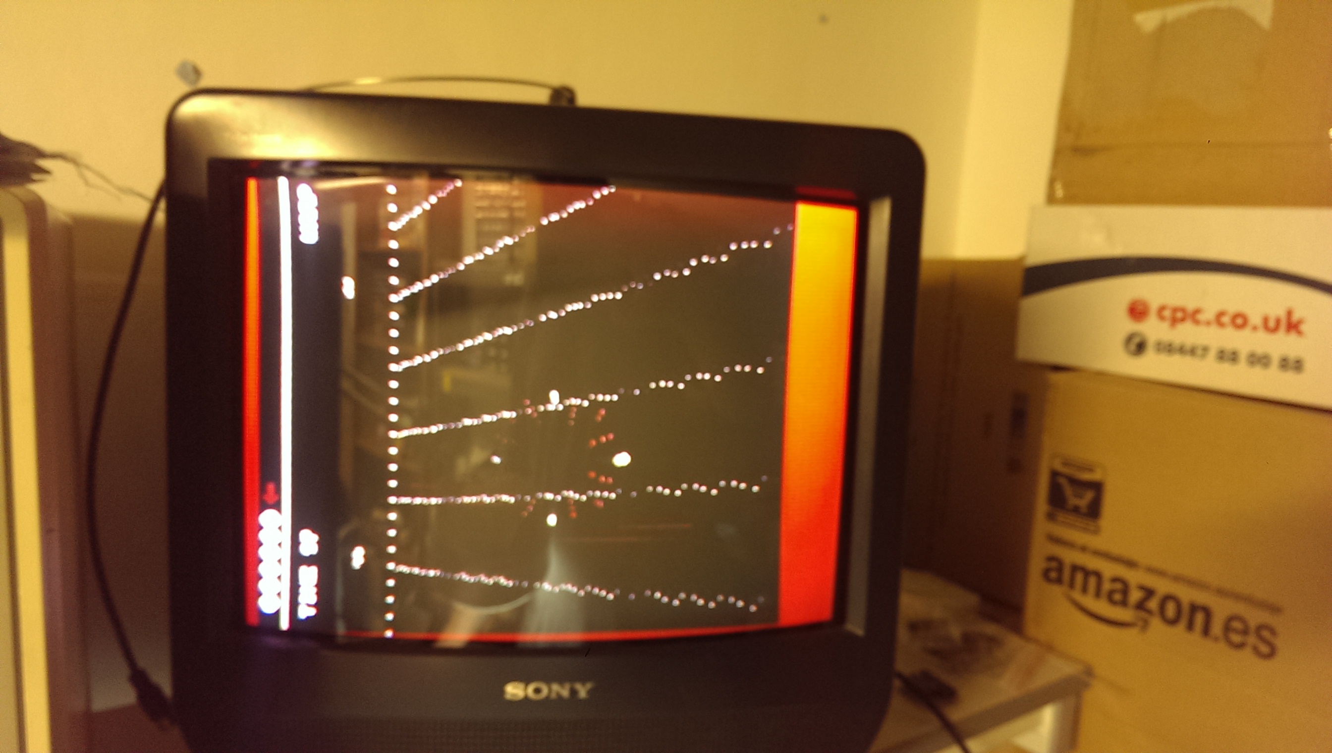
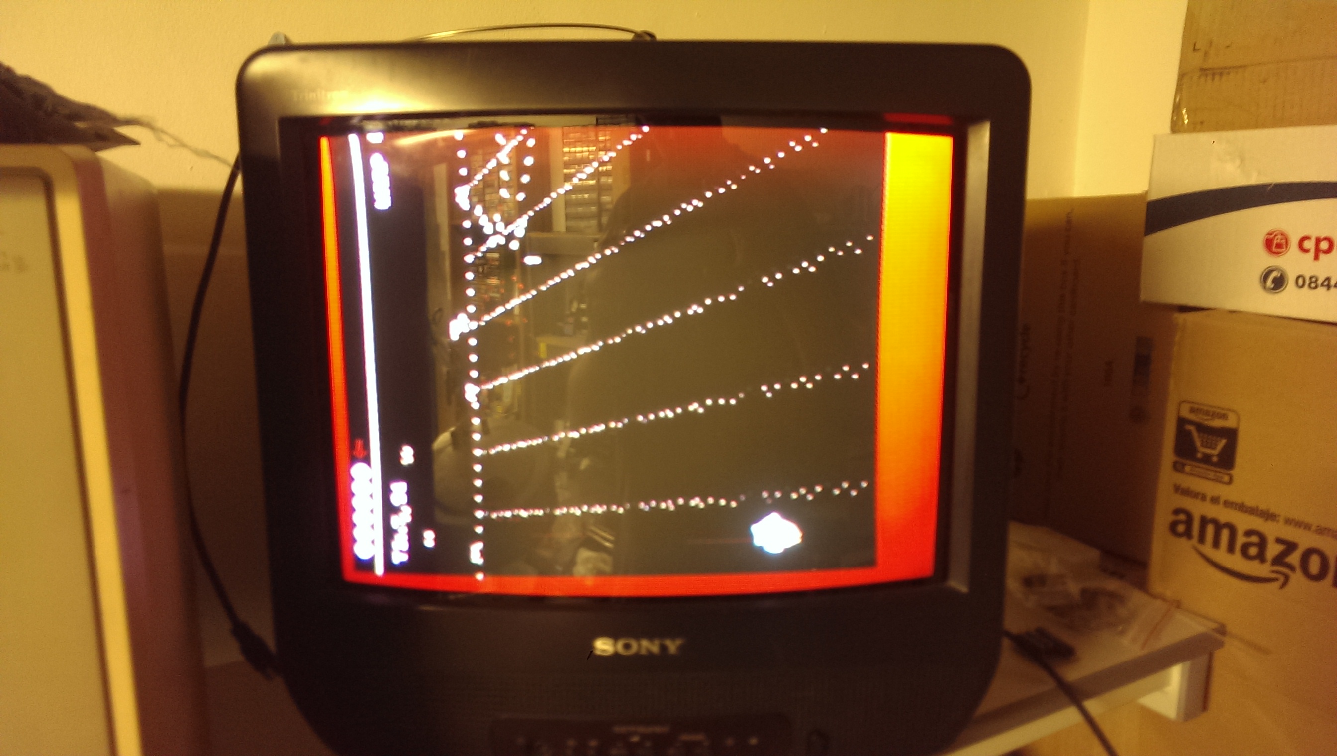
A friend of mine sent me this really mint original Konami GT PCB saying it suffered from vertical stripes across most part of screen.
Fired up the board and …he was right 🙂

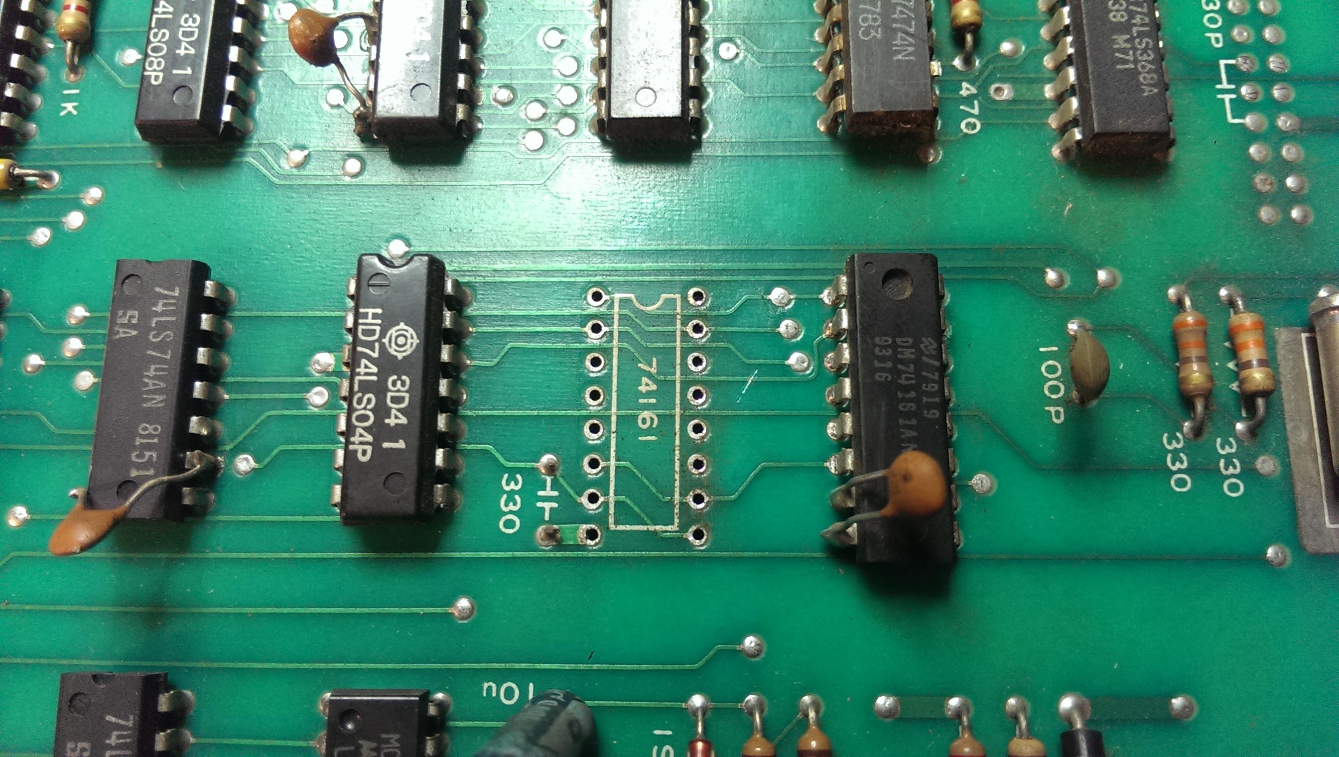
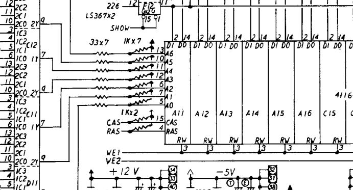
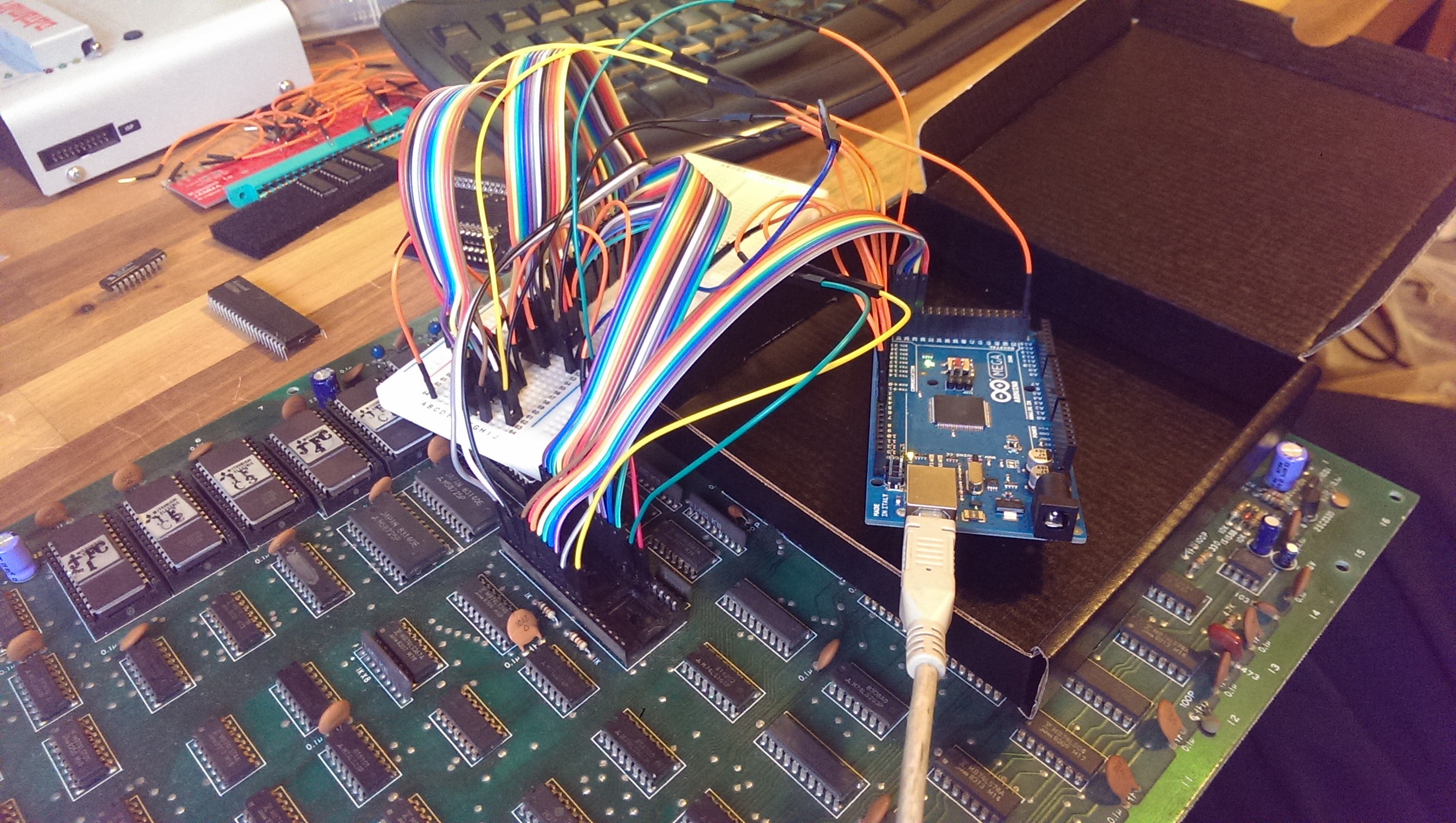
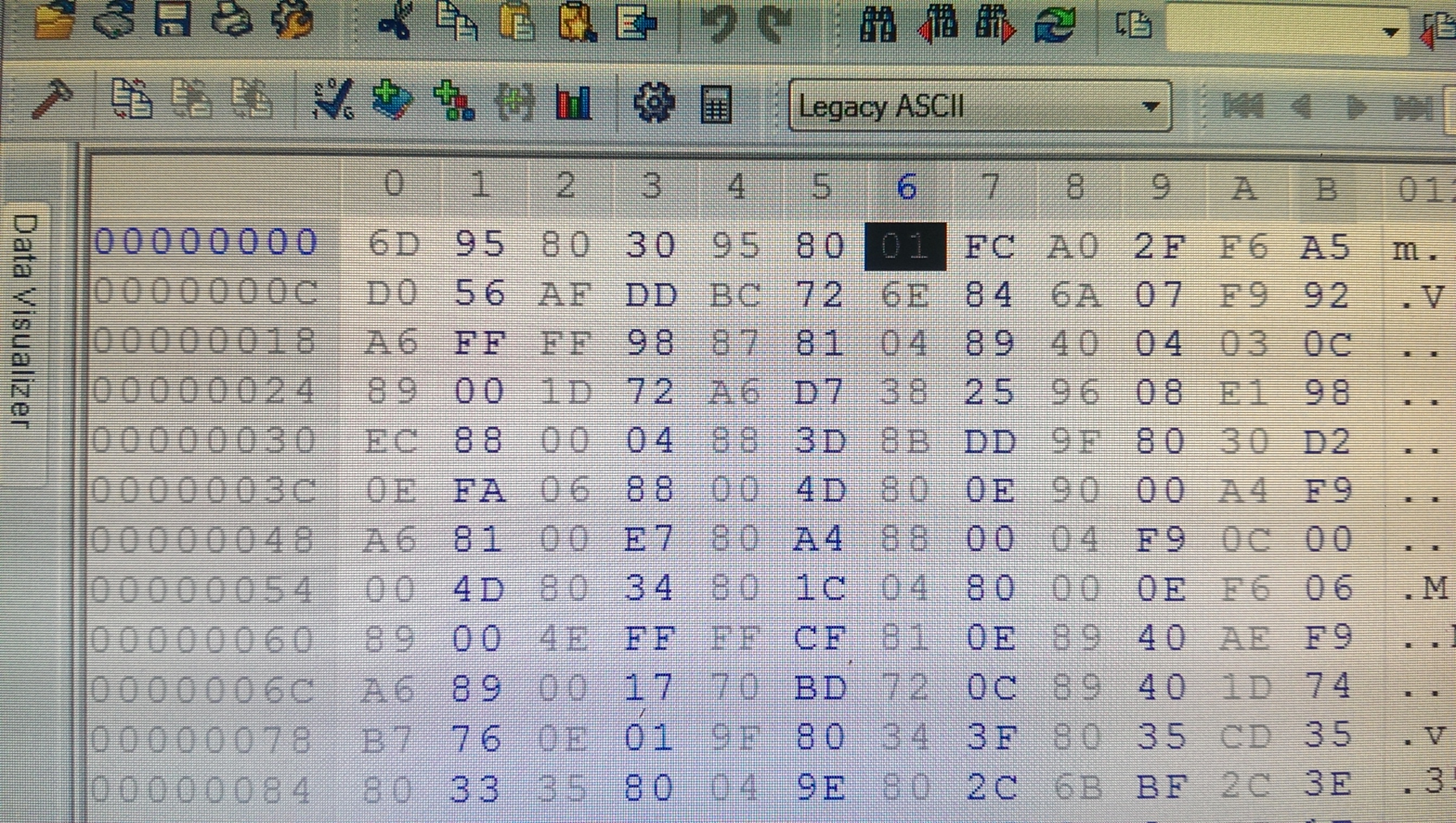
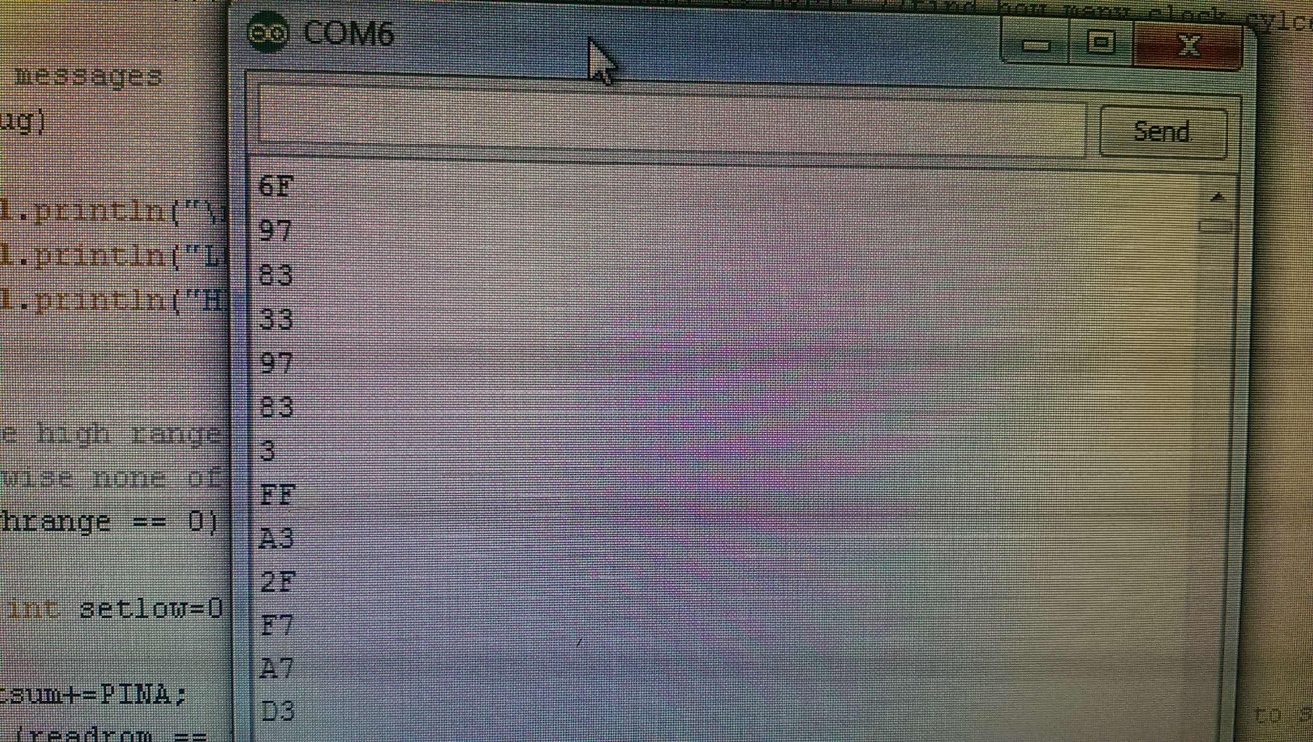
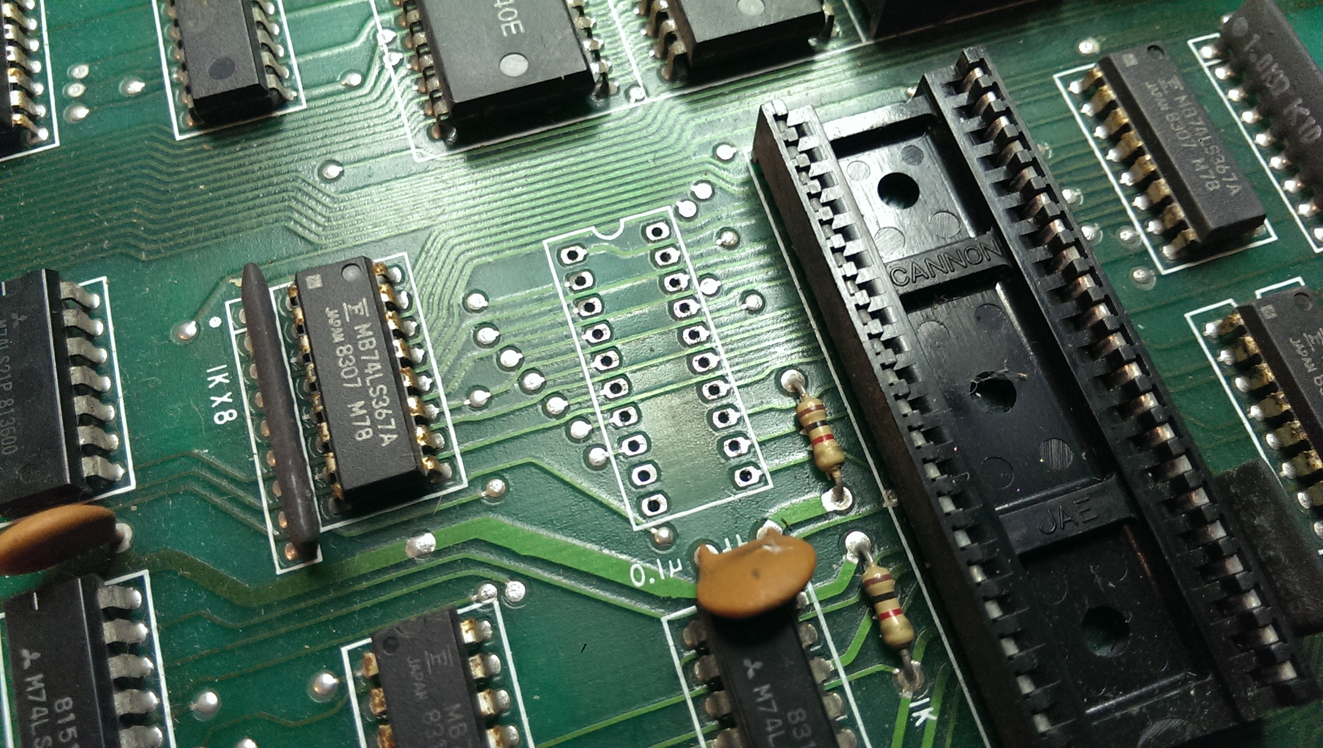
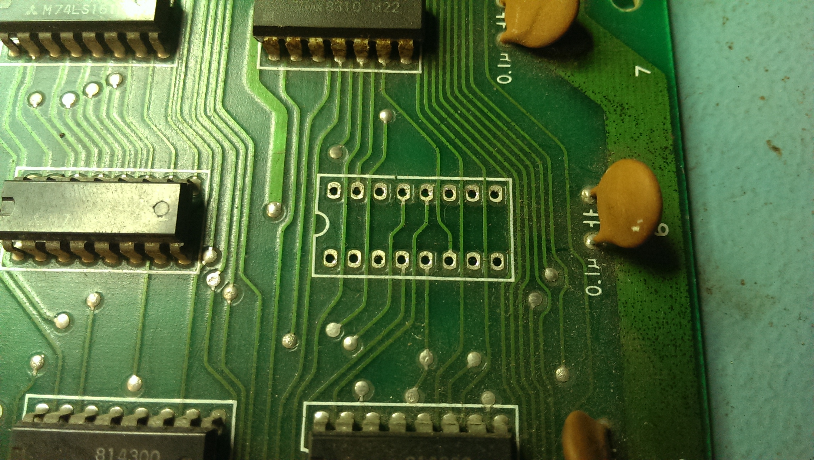
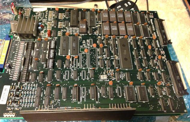
Initial test said all RAMs were good so the problem was elsewhere.Without any schematics I started my visual inspection as usual.I noticed that the only IC replaced on this mint PCB was a 74LS157 @H13.Since a socket was installed, I removed this IC and all the part of graphics affected by stripes disappeared so I started to think problem was generated after this part of circuit.In particular I traced an output (pin 7) of this 74LS157 to pin 4 (RAS) of some TMM4164 DRAMs (there are 16 of them).Probing these DRAMs with my logic probe revelaed that on four of them pin 2 (DATA IN) was pulsing but the pin 14 (DATA OUT) was stuck high.So I desoldered (they were @G2, G3, H4, H5 position) and test them in my Hi-Lo Systems ALL-07A programmer and the result was this:
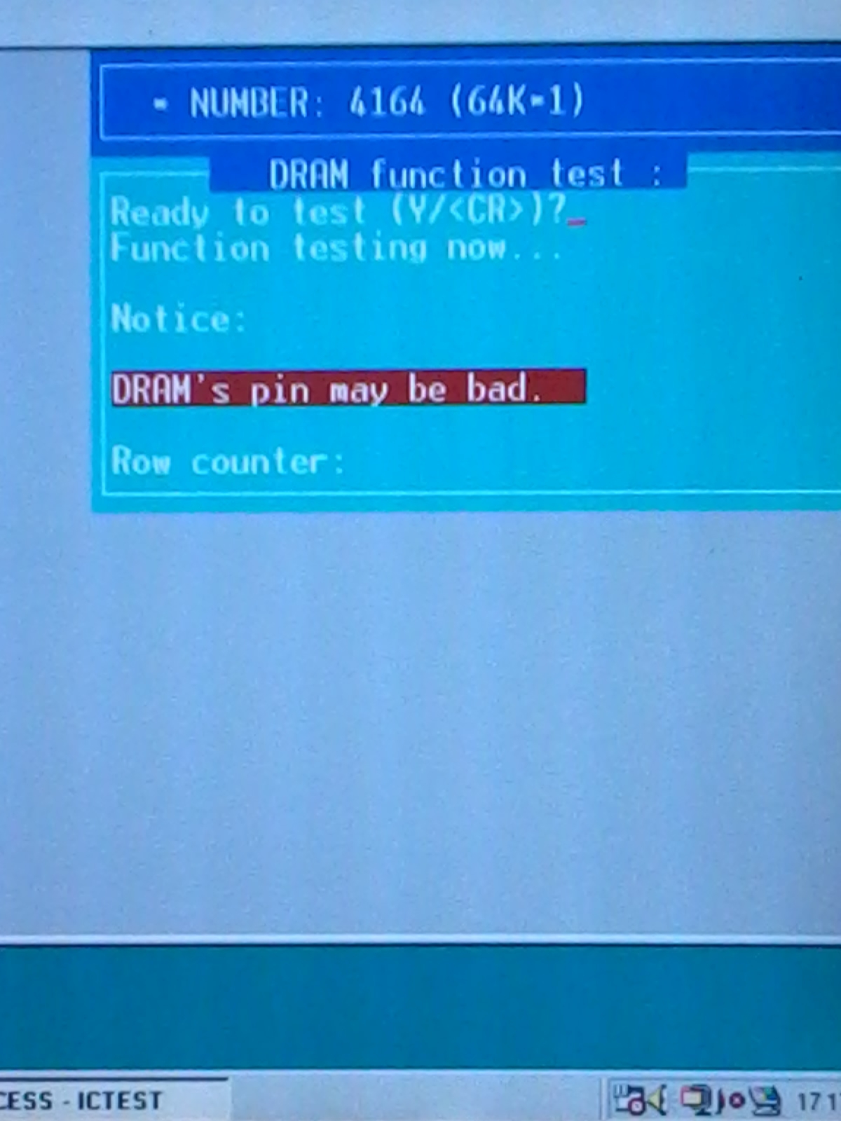
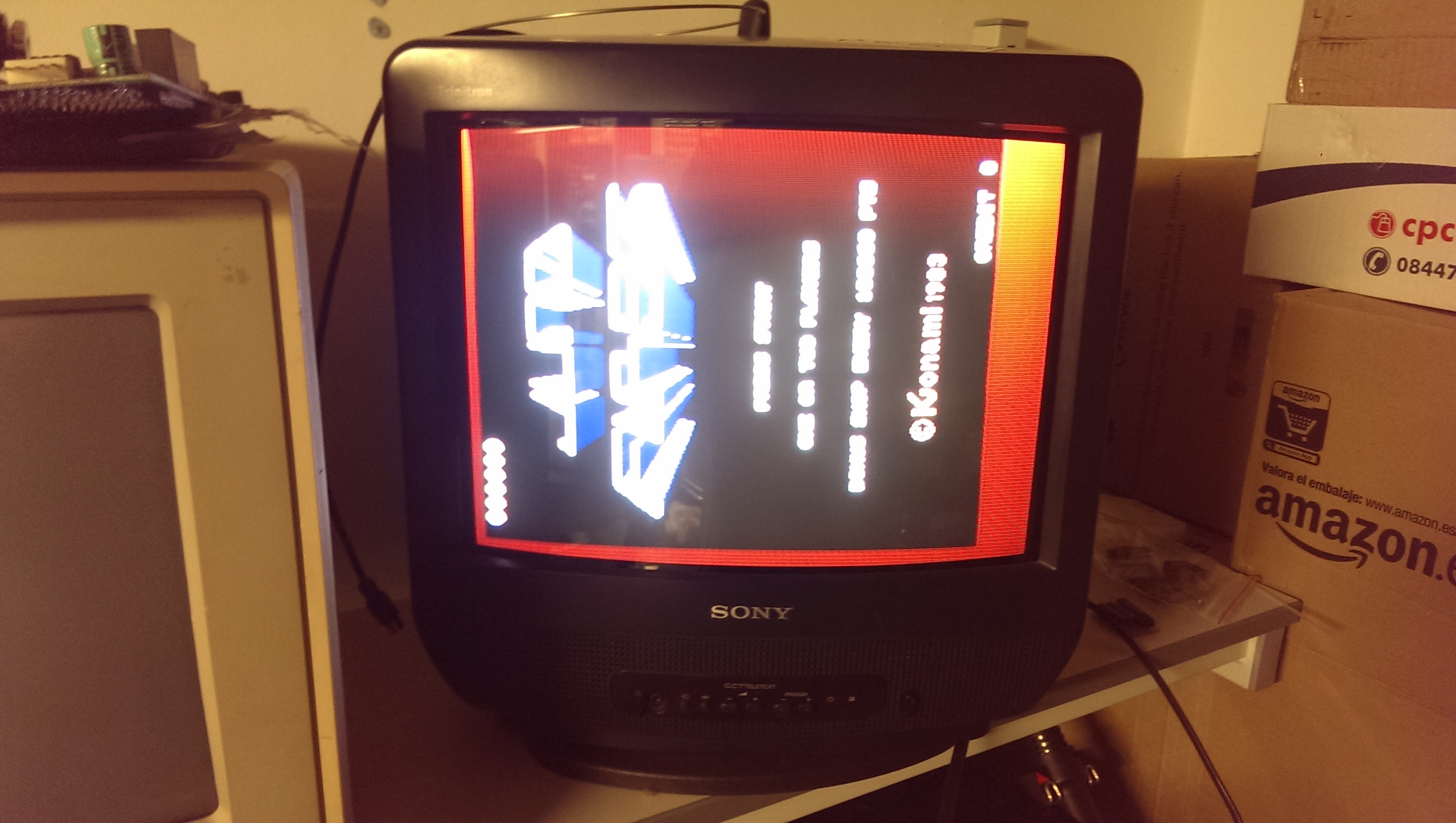
They all failed miserably.I was lucky since had some good 4164 DRAMs taken from a scrap PCB in order to repair a Commodore 64 motherboard.Installed them and goodbye stripes for ever!Board 100% fixed.