Coolmod dumped and submitted PLD dumps from his Jaleco Mega32 motherboard.
These devices were unlocked PEEL devices and are not converted for use in a GAL device or similar.
Thanks to Coolmod for these.
Coolmod dumped and submitted PLD dumps from his Jaleco Mega32 motherboard.
These devices were unlocked PEEL devices and are not converted for use in a GAL device or similar.
Thanks to Coolmod for these.
There is a lot of people out there that need to program a Timekeeper RAM but don’t have the necessary hardware to do so.
Silent Scope 1 & 2 both use one of these and if it dies will display the infamous 11P error.
Recently I decided it would be good to write an Arduino program to do this job.
I have only tested this on an M48Z58Y chip which is almost identical to the M48T58Y only the later has an extra CE (active HIGH) line.
While this worked well for me on the former, it may have issues that need addressed. I have also NOT tested this in any Silent Scope hardware. While the correct data was programmed I have no idea if Silent Scope requires any of the extended functions the Timekeeper RAM offers.
To put it bluntly, this may or may not work for you. If it doesn’t then I have no real way of testing how to make it work with the hardware.
Its a pretty rough program and it is more of a proof of concept than a finished product. Hopefully it will be a starting point for someone to finish or rewrite it.

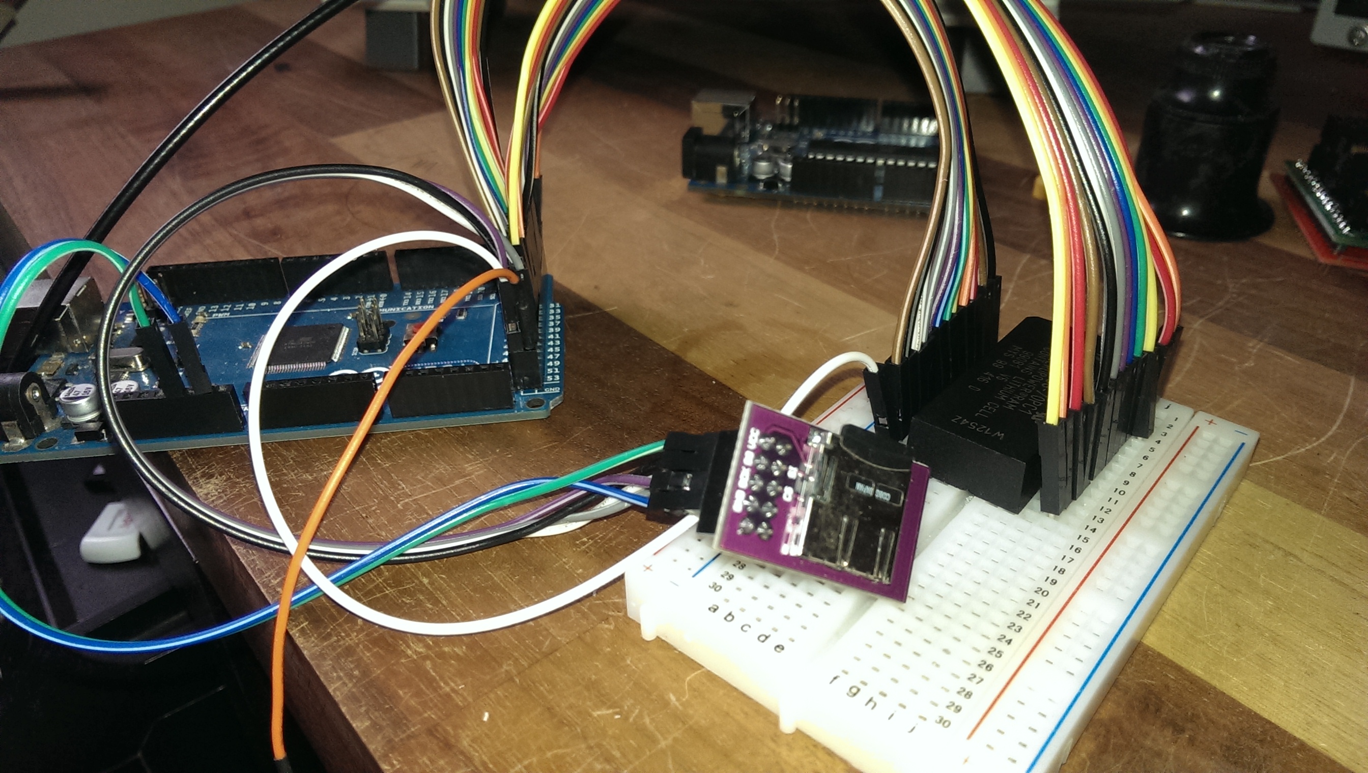
The basic setup requires:
-Arduino MEGA 2560
-SD card breakout board
-Timekeeper RAM
-A valid NVRAM dump (named as “nvram.bin” in the root directory of the SD card)
I Wired up the connections as follows:
ARDUINO -> Timekeeper
38 -> A0
36 -> A1
34 -> A2
32 -> A3
30 -> A4
28 -> A5
26 -> A6
24 -> A7
25 -> A8
27 -> A9
33 -> A10
29 -> A11
22 -> A11
40 -> D0
42 -> D1
44 -> D2
45 -> D3
43 -> D4
41 -> D5
39 -> D6
37 -> D7
23 -> /WE
35 -> /CE1
46 -> CE2
31 -> /OE
The SD card was wired as follows:
53 -> CS
52 -> SCK
51 -> SI
50 -> SO
Don’t forget to wire up you VCC and GND for both of these too.
All these pin assignments can easily be changed in the program if you wish.
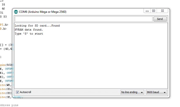
Once the ‘sketch’ has been loaded up from the IDE if you open the terminal window (9600 baud) and everything is configured correctly you should see the following text.

Send an upper case S and a few seconds later it will hopefully have finished and the chip should be programmed.
The ‘sketch’ can be found in the Arduino download section.
Had Muddymusic’s Stun Runner PCB for a long long time awaiting repair.
I put off looking at it because of how test bench unfriendly it would be to setup.
I did have most of the original loom to use but the audio section also used 13v AC and a test bench typically doesn’t have that.
I ordered a small 240v – 12v transformer and eventually set to work in hooking this thing up.
After half a day of messing around I had what I thought was a Stun Runner test rig.
While I had all the connections going to the right places and things like that I soon realised that the speakers I were using in now way suitable to check the sound and also my test bench monitors seem to be getting really picky about what they display properly.
In the end I settled for a black and white picture but I wasn’t too worried as the fault I was looking for was audio related.
The fault was that in game the music didn’t play and the engine tone played at a constant tone.
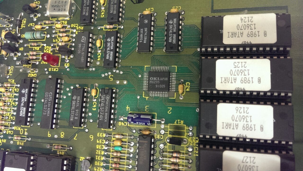
With my almost useless setup I could hear exactly this. I did a quick heat check with my finger on the audio PCB to check if any of the chips were getting hot and to my surprise all the sounds and music came back when I prodded the M6295.

I powered down and reflowed the chip and all was working again.
I soak tested it as best I could and called it a day.
Muddymusic has now got it back and has confirmed the sounds and music are now good.
cmonkey needed a replacement 315-5224 chip for his Outrun board.
We have a bunch of PLD dumps from an Outrun board but they are untested and are from an unknown source.
The original 315-5224 is a PLS153 and cmonkey needed it in a GAL16V8 in order to replace it.
The equations themselves aren’t too complex and would fit nicely into a GAL16V8 as the extra IO pins on a PLS153 are actually configured as inputs which makes it pin compatible.
Equations:

PIN 13: /ROM_CE = /MREQ & RFSH & RAM_CS & DACS

PIN 14: /RAM_CS = A11 & A12 & A13 & A14 & A15 & /MREQ & RFSH

PIN 15: /YM_CS = /A6 & /A7 & /IOREQ & M1

PIN 16: /DACS = /A11 & A12 & A13 & A14 & A15 & /MREQ & RFSH

PIN 19: /ZCS = A6 & /A7 & /IOREQ & RFSH
The problem came with needing to use the feedback from pin 16 in order for it to work.
When compiling equations for a GAL16V8 you need to specify what mode you want to use it in. There are three modes a GAL can be used in.
1. Simple
2. Complex
3. Registered
The PLS153 cannot be used as a registered device so we cannot use this mode.
‘Complex’ cannot be used as we need to use pin 12 as an input and pin 12 does not provide any feedback in this mode.
‘Simple’ mode is what we need to use but in this mode pins 15 and 16 cannot provide feedback which is exactly what we are wanting.
Looking at the equations and the schematics we can see that pins 17 and 18 are actually unused. These pins can also provide feedback in ‘simple’ mode.
The workaround for a GAL16V8 is to copy the equations for /o16 and add them to /017 then change the equations for /o13 to use feedback from o17 instead of o16, like this:
Equations:

PIN 13: /ROM_CE = /MREQ & RFSH & RAM_CS & DACS2

PIN 14: /RAM_CS = A11 & A12 & A13 & A14 & A15 & /MREQ & RFSH

PIN 15: /YM_CS = /A6 & /A7 & /IOREQ & M1

PIN 16: /DACS1 = /A11 & A12 & A13 & A14 & A15 & /MREQ & RFSH

PIN 17: /DACS2 = /A11 & A12 & A13 & A14 & A15 & /MREQ & RFSH

PIN 19: /ZCS = A6 & /A7 & /IOREQ & RFSH
cmonkey has confirmed this works on his Outrun PCB.
Although this worked well I was not happy with the workaround. The resolution turned out to be simple.
If I took the newly programmed GAL chip and re-dumped it using Charles MacDonald’s hardware I got a list of valid equations that did not rely on the use of feedback at all.
Since the equations were few, it had no problems in fitting into a GAL16V8 and so I ended up with something that left those two unused pins free which is good because cmonkey has a use in mind for them.
Star Jacker has two PAL16R4 chips on it. Looking at the schematics for Star Jacker and Choplifter I saw the PALs on both of these boards are very similar. The 315-5138 from my Choplifter board works fine in place of the 315-5024 PAL on the Star Jacker board.
The other one has a couple of differences. Pins 13 and 19 are swapped and pin 17 has a different designation altogether but it looks the same apart from that. I will try and recreate this chip soon.