Welcome to Pantman. Another good source of repair logs coming now.
Happy new year to everyone too
Welcome to Pantman. Another good source of repair logs coming now.
Happy new year to everyone too
Today we have another contributor to the website.
Welcome to my good friend Equites.
This is the first in hopefully a series of posts regarding the Rainbow Islands hardware.
I have no time frame in mind for releasing these posts and I will do them when I have any particular section covered.
First up is the reset/watchdog circuit.

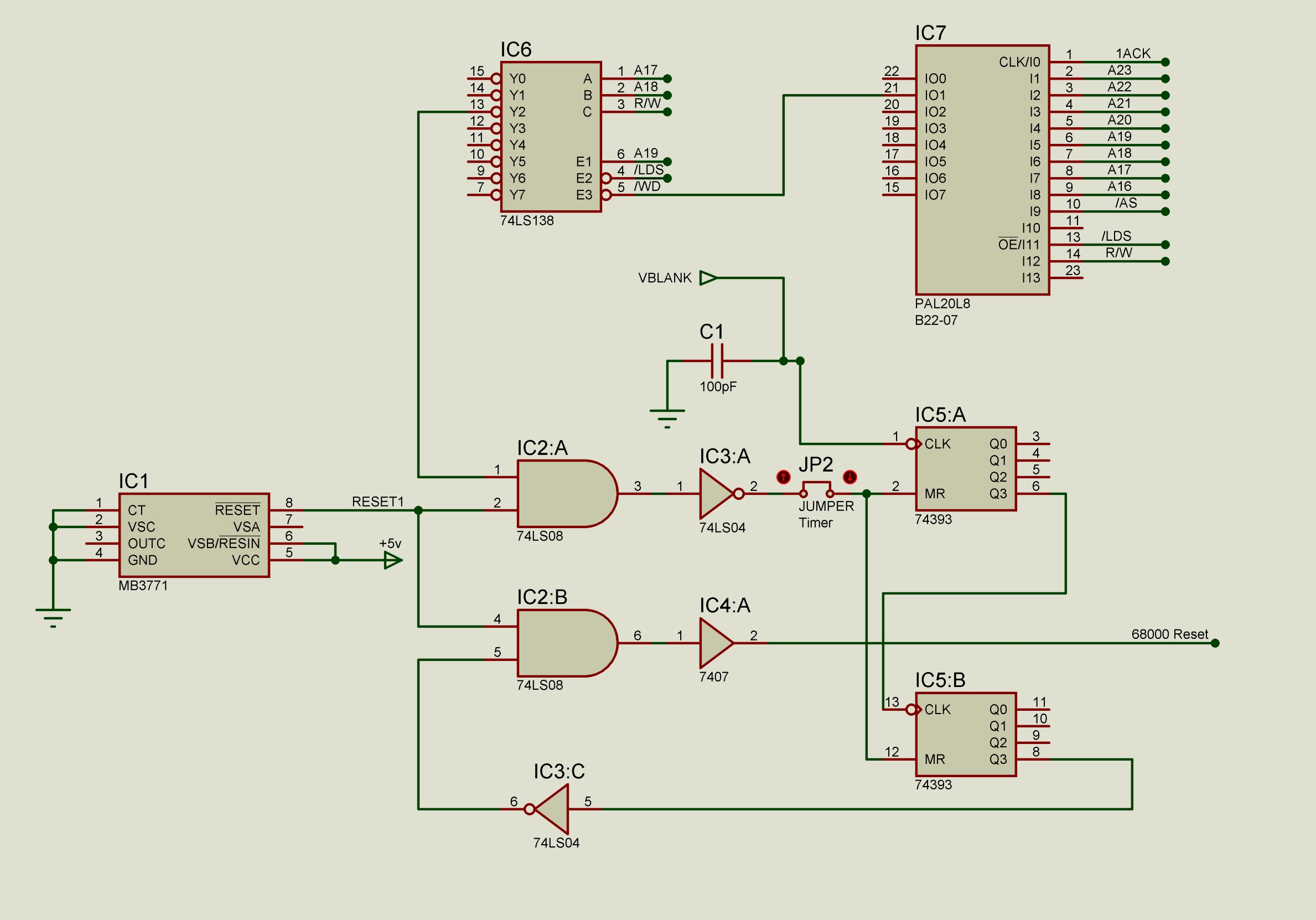
Here we have the circuit that I have drawn out.
On power up the MB3771 power supply monitor chip will keep the CPU in a reset condition by asserting a low signal to pin 4 of IC2 (74LS08 AND gate).
At the same time the master reset pin of the 74393 4-bit binary counter is held high thanks to the inverting buffer at IC3.
Note, jumper JP1 can be used to disable the watchdog although I couldn’t find a resistor tying it high which would mean if the trace was cut on JP1 the MR pin would be floating. Maybe I just cant see it.
Once the MB3771 is happy it asserts a high signal from pin 8 which will allow the 68000 CPU to run and the watchdog timer to begin.
The watchdog clock is taken from the VBLANK signal and directly clocks the first binary counter at pin 1 which in turn clocks the secondary binary counter via output pin 6.
If the master reset pin in not activated within a certain time then the counters will count up and initiate a reset.
The watchdog reset signal is achieved by writing any value to an address between $3c0000 – $3dffff.
The memory map for the watchdog is determined by the PAL20L8 device B22-07 @ IC7.
Output pin 21 is the pin concerned with this function. Here are the equations for it.
!WD = 1ACK & !A23 & !A22 & A21 & A20 & A19 & A18 & !A17 & !AS
# 1ACK & !A23 & !A22 & A21 & A20 & A19 & !A18 & A16 & !AS
# 1ACK & !A23 & !A22 & A21 & A20 & A19 & A17 & !A16 & !AS
This output goes to a 74LS138 decoder/demultiplexer. Output pin 13 is the watchdog reset output.
That’s pretty much it. Simple and nothing much out of the ordinary.
I’ve started drawing out Irem’s M84 hardware. I’m using an R-Type II PCB so the ROM names are specific but the overall layout and functionality should be the same across the games.
I used the M81 schematics I made as the base as the hardware is very similar.
This will be updated as I get around to it or until I no longer need to carry on with it.
Available in the ‘Downloads/Schematics’ section.
A while back it was identified that the replacement GAL I made for the Amstrad 6128 didn’t play nice with some/all memory expansions.
As I wasn’t able to test any expansions it was always a bit of a concern.
Anyway Gerald over on the CPCwiki forum has revised the equations and has fixed the issue. It was being caused by some improper use of the RAMDIS signal.
Thanks to Gerald for fixing this.