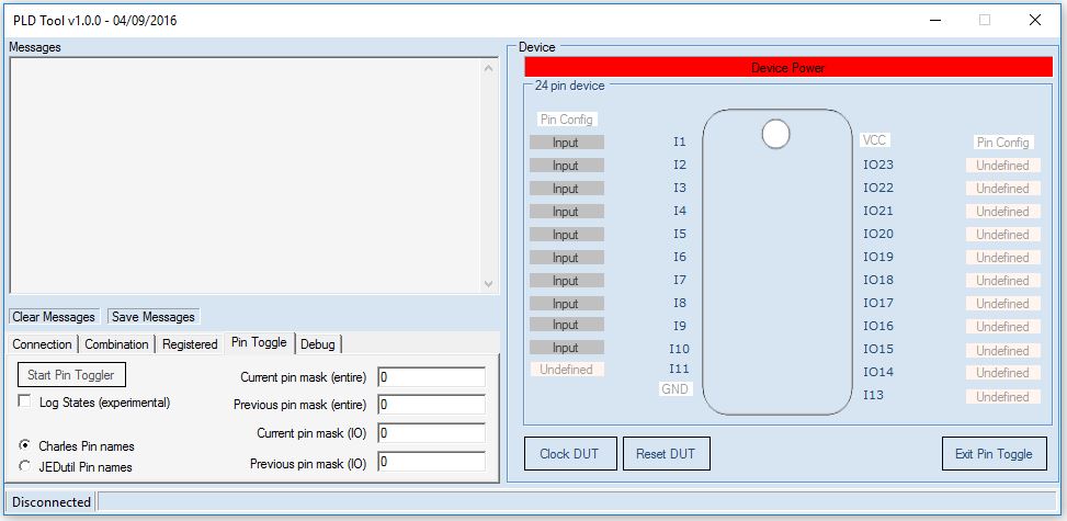
This has been my main project for a long time now. Its something I started initially on the ABI Boardmaster 4000 as simple pin toggle routine. This allowed me to toggle the logic states of any pin and get a live update of the state of all the pins.
When I first got my Arduino MEGA I decided to port the program over to that as my first project.
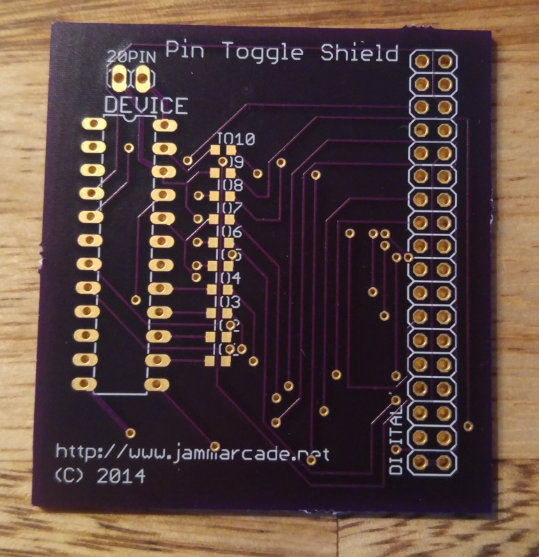
PIN TOGGLER

It ran through a terminal window and was pretty much identical to the BM4K version I made.
It has a jumper on the board to switch power between 20 and 24 pin devices.
Revision 1

From this point I wanted to have a Windows GUI so I could have a graphical environment when using my ‘pin toggler’.

I also moved to using the ports of the Arduino to speed accessing up so with this in place I added the ability to brute force the operation of the chips so Caius could recreate 24 pin devices. The method used was identical to the way Charles MacDonald’s device worked so to keep compatibility with his analyser program. I don’t really require the ‘dumping’ feature of this as I use the hardware from Charles and its a lot faster to use but this option is there if I ever need it.
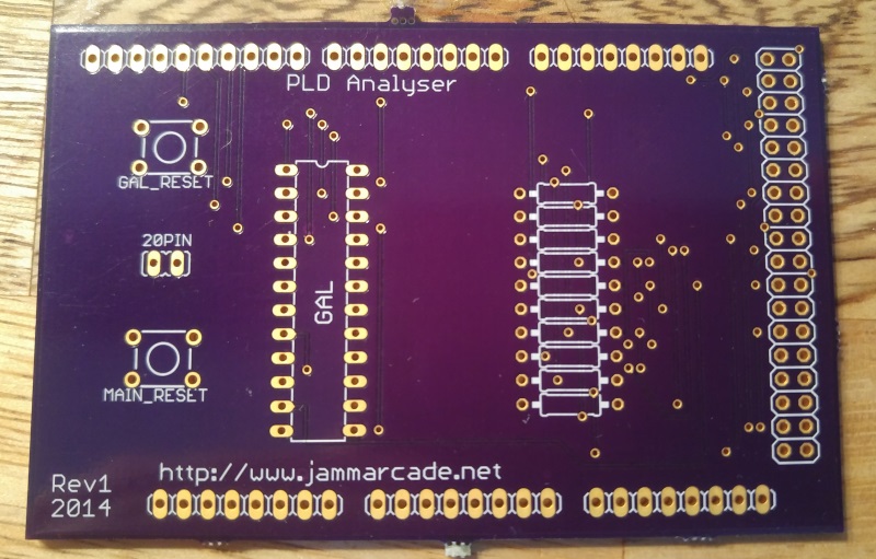
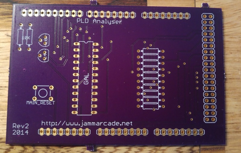
There were a couple of other things I wanted to add too from a hardware point of view. I added two reset buttons to the ‘shield’. One was to reset the Arduino itself and one was to reset the PAL/GAL in the socket. The jumper was still present on this revision to select 20 and 24 pin devices.
Revision 2

Not too long after revision 1 I decided I wanted to be able to control the power to the chip from the software. As you can see the jumper is gone and got replaced by a couple of transistors and resistors. Using this setup I could easily select 20 and 24 pin devices using software. I don’t think there were any other changes here.
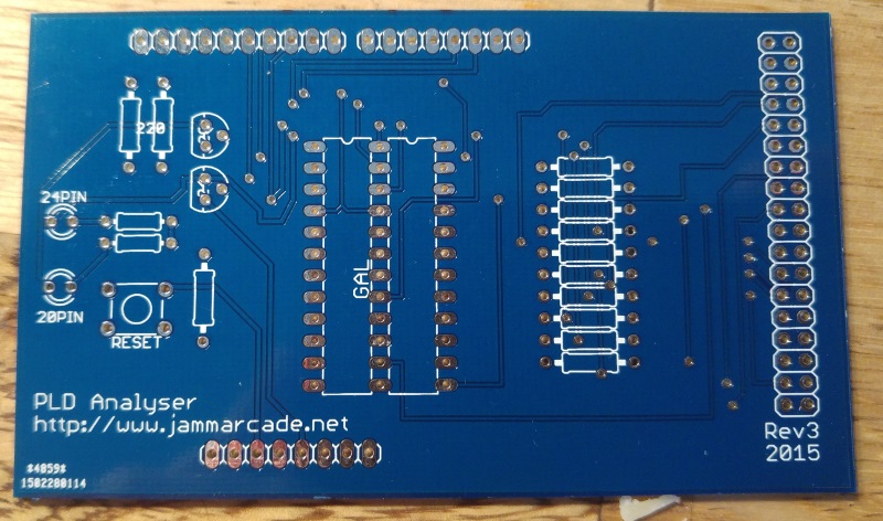
Revision 3

This is where things started to gain momentum within the project. I spent a lot of time changing the software for this one.
So the hardware had a couple of obvious changes. First was I added LED’s to show which device type was being used.
Second was the socket itself. I had bought a ZIF socket for the project but it had 0.6″ spacing so in order to let me select between the two should I need to, I added both to the layout
The software got a big update this time around with many things being rewritten.
Myself and Caius had started to realise that there were quite a lot of PAL’s out there that used latches. Latches can be implemented in a non registered IC by using the feedback from an output pin. In some cases we haven’t even realised that latches were being used and it was only later we found out when people raised an issue.
To check for latches I added the ability to dump the PAL backwards so instead of counting the applied address up it counted down. It performed a forward and reverse operation then compared the results. If they were a match then it was a good bet that latches weren’t being used. I also added the option to use random addresses too which would give a more thorough test but took a lot longer to complete. I have never really needed to use this so far.
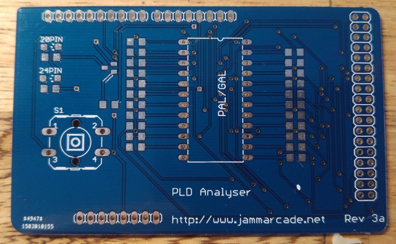
Revision 3a

This revision moved to surface mount components, removed the ability to use 0.3″ space ZIF socket and also added extra resistors. The resistors on the input only pins were there for protection in case of shorts.
Aesthetically, this one had rounded corners.
The software added support for those 20 pin devices that had an extra IO pin at pin 9 like the PLS153 and GAL18V10 although the supporting analyser software didnt support this so it never got used but it meant the pin toggle part of the software could use it.
Version 2

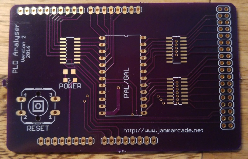
So here we have Version 2. All the previous iterations were what I called version 1. This one never turned out as I had hoped. I moved away from using ports on the Arduino which was a massive mistake. I did gain complete flexibility though. I had been studying some strange devices with a non standard IO configuration. This was going to be my of dealing with those devices. Unfortunately it became painfully clear that my software was so rigid that it didn’t allow changes to be easily made.
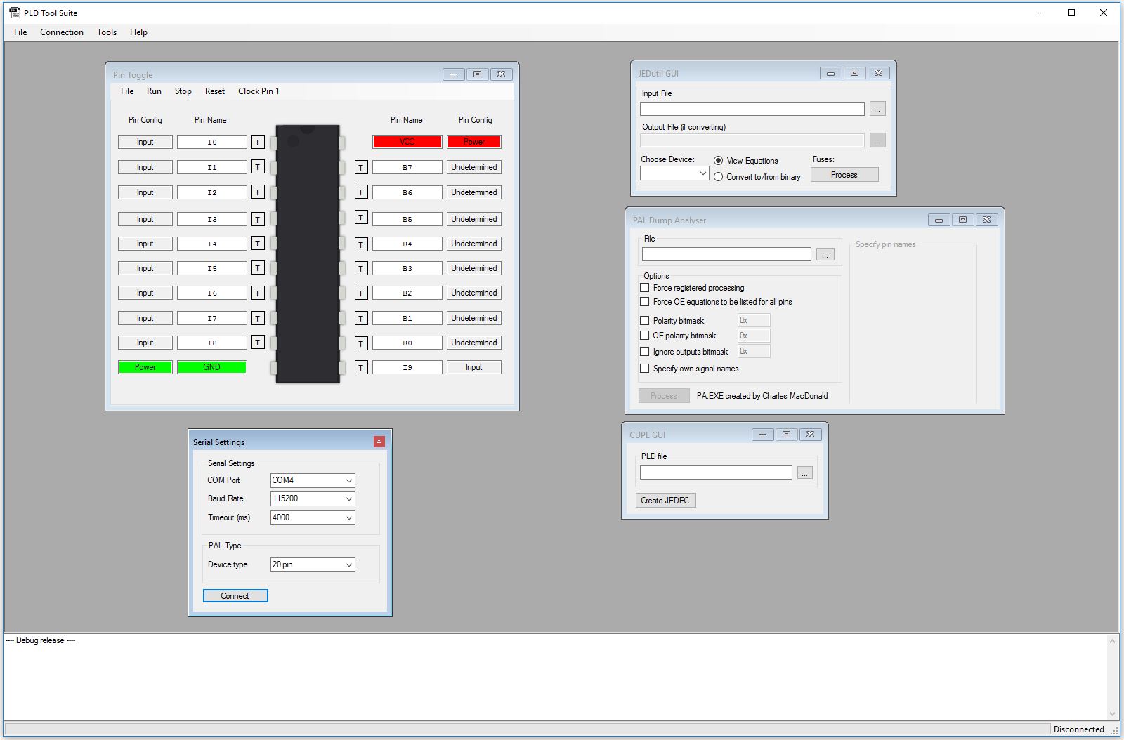
At this point I decided to rewrite my software from scratch opting for more of a suite environment for all this PLD rather than a simple bit of software.

The software as it stands right now is my proudest creation. It has GUI’s for MAME’s JEDutil and Charles’ analyser program and also the commandline version of WinCUPL too allowing everything to be done in the same place easily. It can also be set to automatically analyse a ‘dump’ and compile to a fusemap.
That’s where this project is right now. I’ve not finished with it yet but its not actively being developed either.
Hopefully I will get back to it at some point but at this moment there isn’t too much need
