frsj8112

Namco Rompers repair log

 PCB Repair Logs, Repair Logs  Comments Off on Namco Rompers repair log
Aug 032024
 

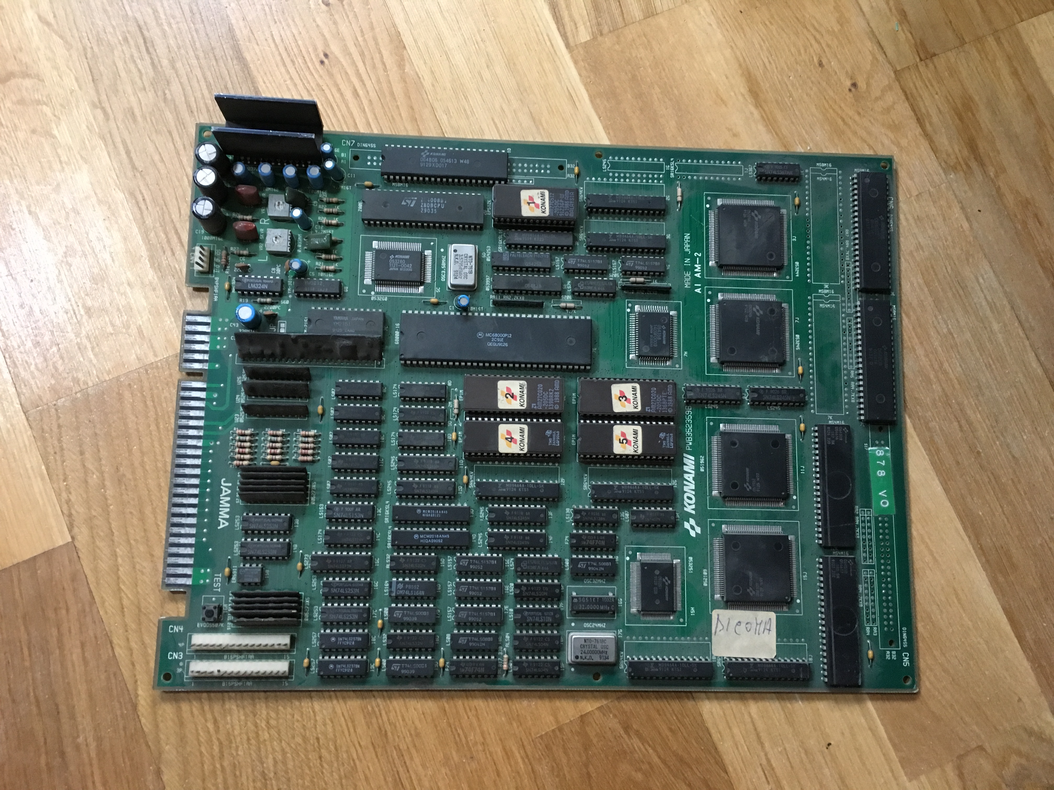
I’ve had this board in my collection for some years and I’ve made some repair work on before (replacing the cus120 on the CPU board, might put up a repair log on that as well).
I was going through my PCB collection and found that the game would not boot, there was only a black screen and not even the usual klonk sound as Namco System 1 games usually do.

Started with the basics, probed the Program ROMs with my logic probe and I did see some activity on the address and data buses.

Decided to dump the Program ROMs and verify them and they turned out to be ok.

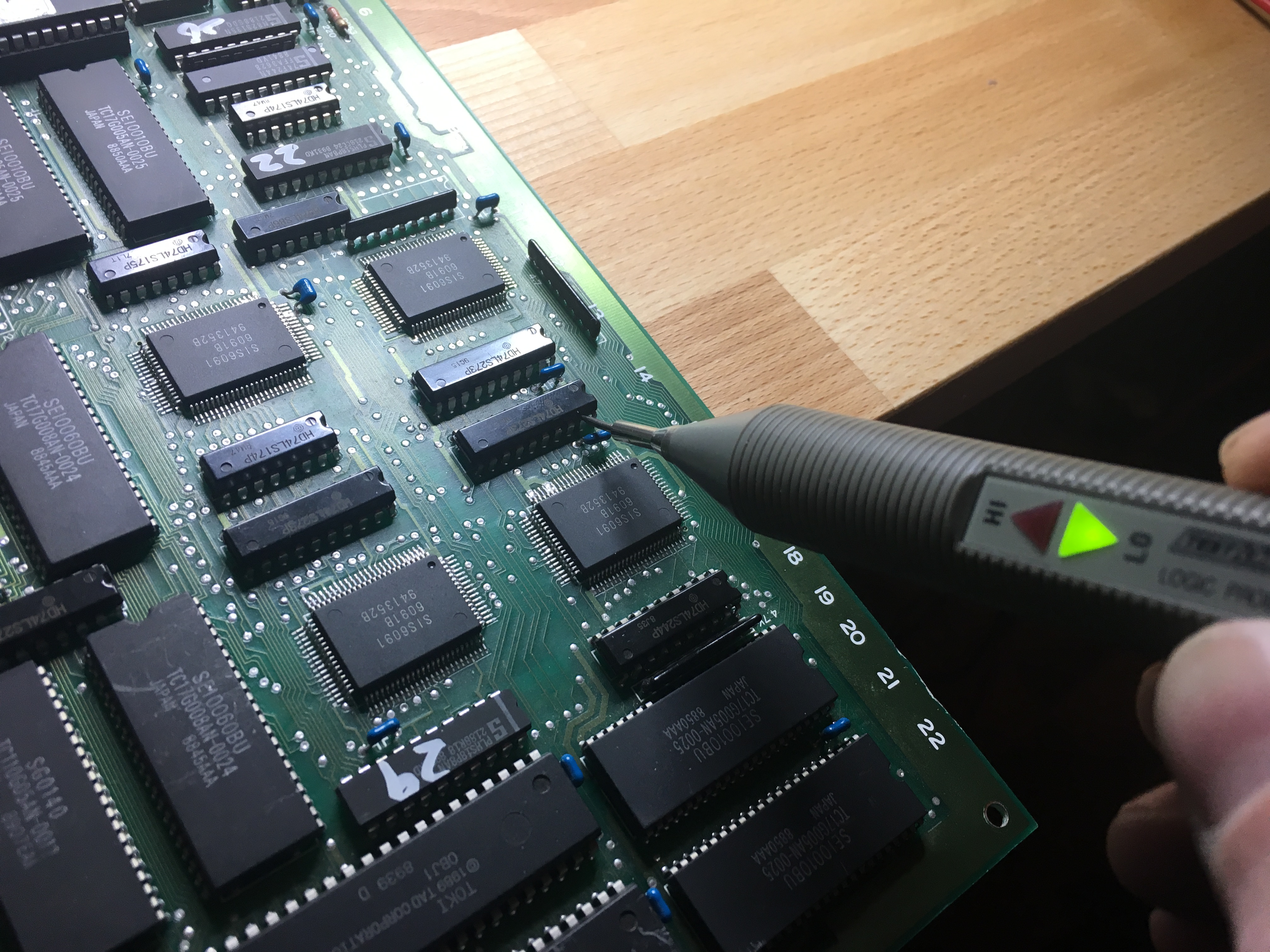
So I started to probe the address and data buses again and found an address line (A2) that was stuck low.

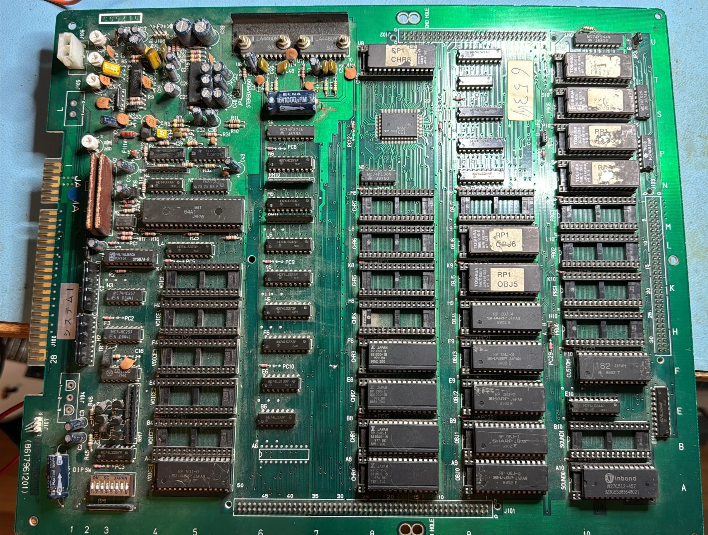
Traced this line back to a 74LS244 at E10

74LS244 is a buffer and according to the Pac-Mania schematics, pin 14 is the output which has its input at pin 6 and there was activity there

This made me quite certain that the 74LS244 at E10 was bad.
But just to be certain, I removed all Program ROMs and the Custom key chip, so none of them would interfer.

And the fault was still there.
I quickly desoldered the 74LS244 and tested it with my tester as bad
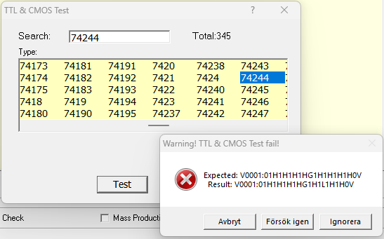
I soldered a socket in its place and replaced the IC with a known good one and now the game booted up again

Dec 022018
 

I have two Toki pcbs in storage, both with sprite errors. I saw a video from lukemorse1 (who actually inspired me to start repairing arcade pcbs) on youtube where he worked on a Toki pcb, also with sprite errors.

Here’s how the error on board #1 looked like:

So there are blocks surrounding the sprites.

From Luke’s video (https://youtu.be/Czdt_yTNRTs)ย I identified the area responsible for sprite handling and I quickly found a 74LS273 with a stuck output at pin 19:

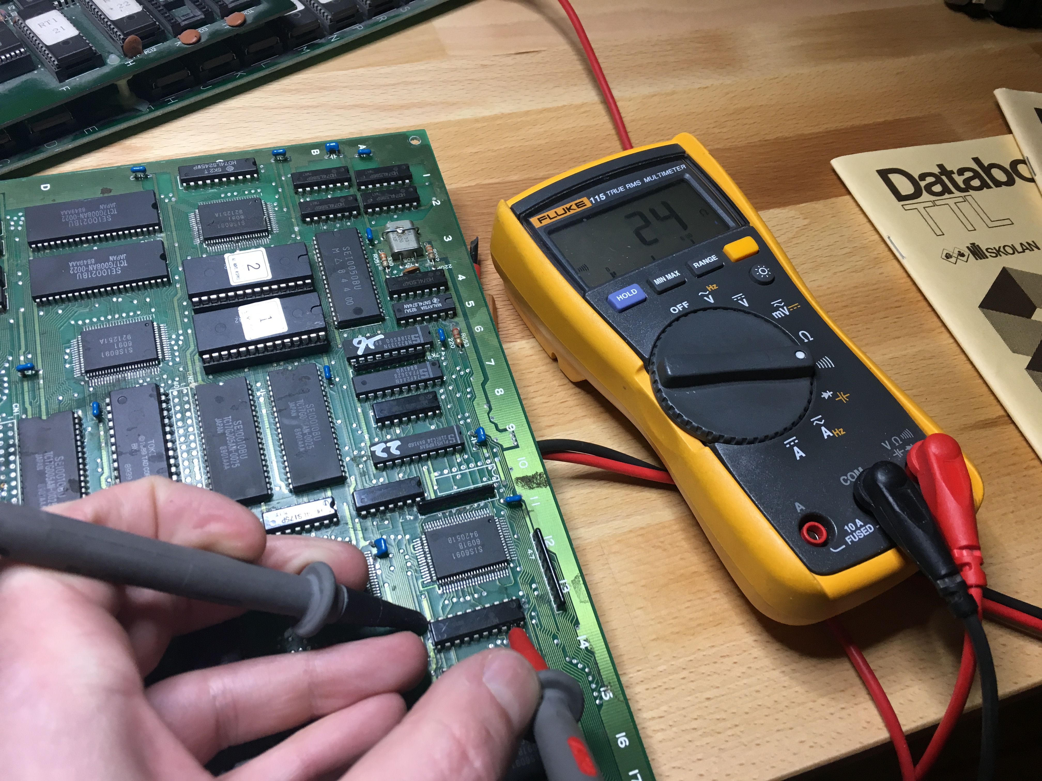
Checking with the multimeter, I found that this pin was almost shorted to ground:

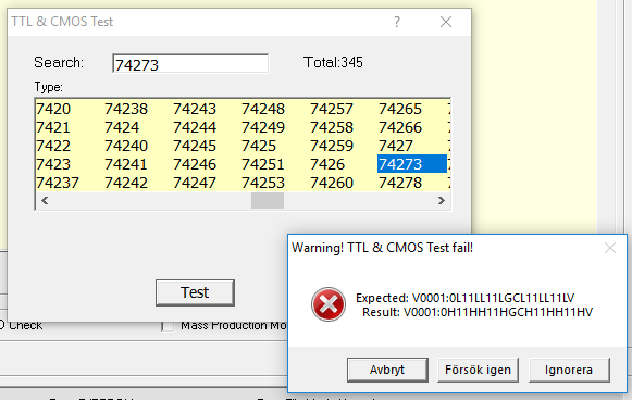
I quickly desoldered the IC and tested it with my VP-398

Replacing it with a working 74LS273 made the sprites appear as they should:


So a big thanks to lukemorse1 and also as always to caius for always helping out ๐Ÿ™‚

Sunset Riders repair log #8

 PCB Repair Logs  Comments Off on Sunset Riders repair log #8
Jun 042018
 

Was asked by a friend to repair his Sunset Riders.

When starting up the PCB, it was stuck in something resembling a watchdog fault.

But I’ve been working on Sunset Riders before and this didn’t seem like an ordinary watchdog. I felt that it went a little bit longer in the startup sequence before crashing.

The board was a bit dirty but I started with the usual:

  • Checking CPU signals like clock, reset and halt
  • Verifying the program ROMs
  • Checking the program RAM for odd signals

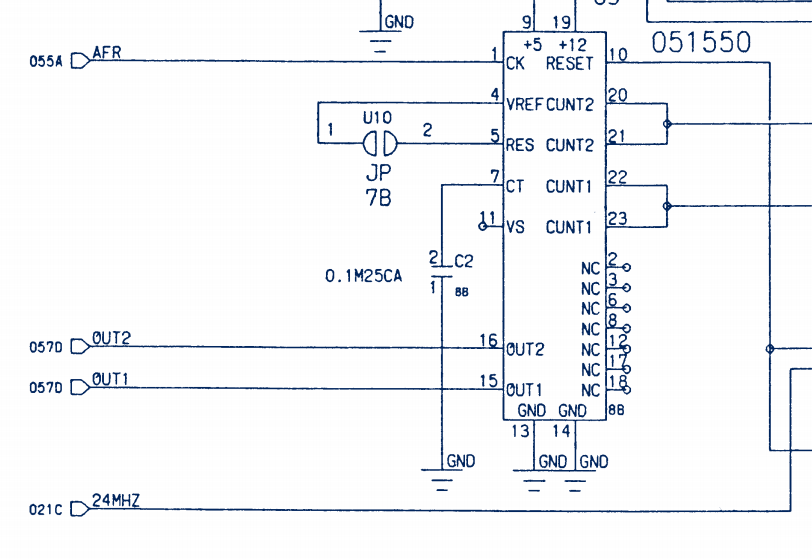
All looked ok, but then I found this at the 051550 reset signal generator.

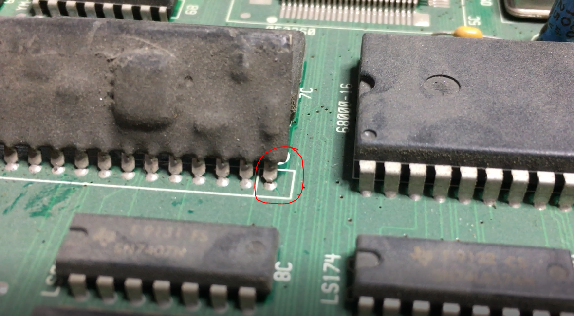
Pin 1 on the 051550 looked like a cold solder joint.

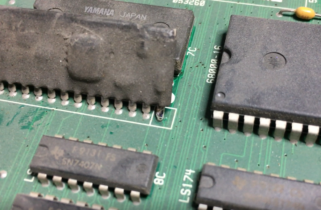
Pin 1 is the clock signal input pin on this IC and without that input, I can understand that the game doesn’t boot up properly. Gave that pin a dab of solder

And booted up the game

Board fixed without any other issues ๐Ÿ™‚

Robocop repair log #3

 PCB Repair Logs  Comments Off on Robocop repair log #3
May 162018
 

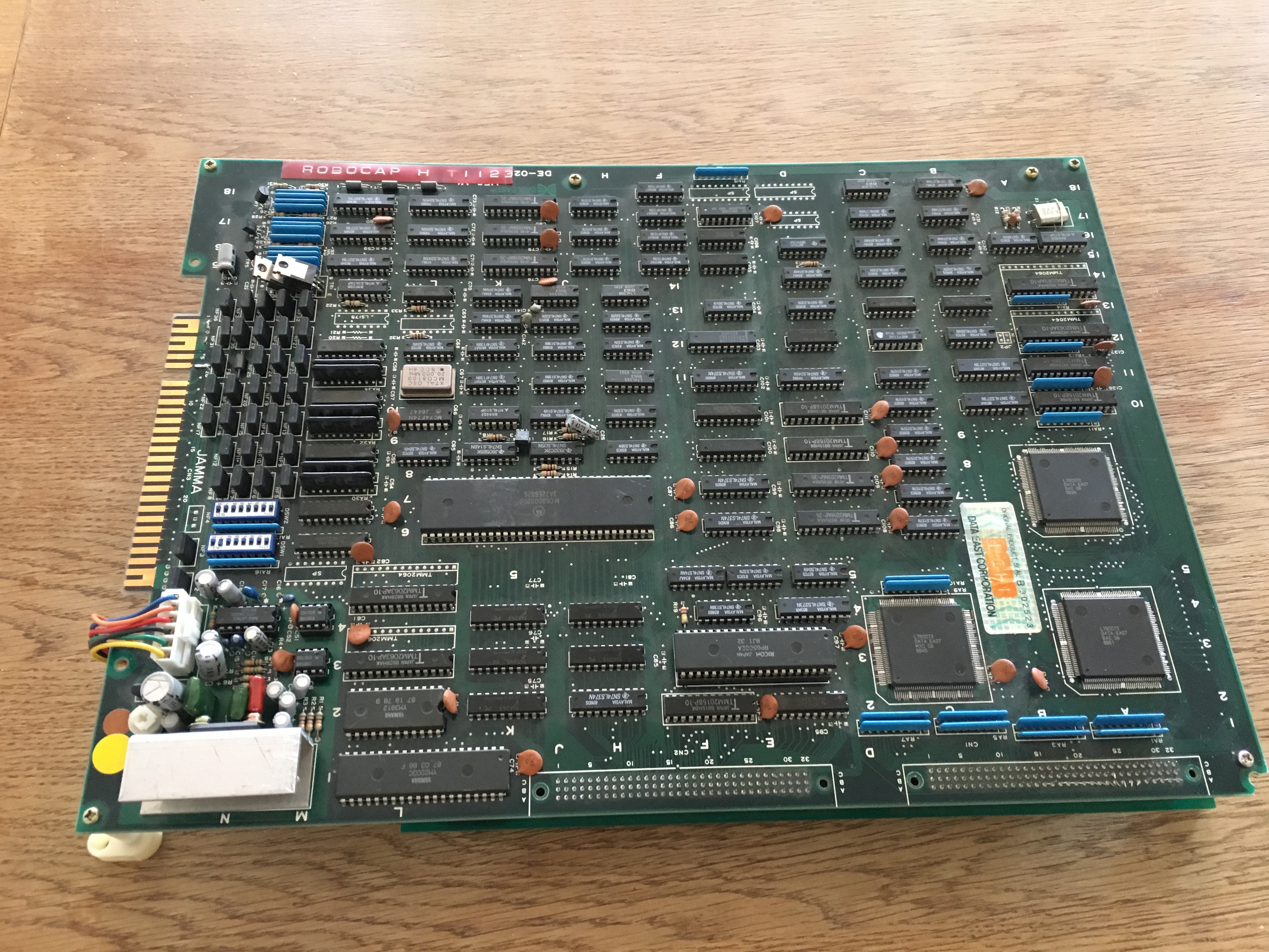
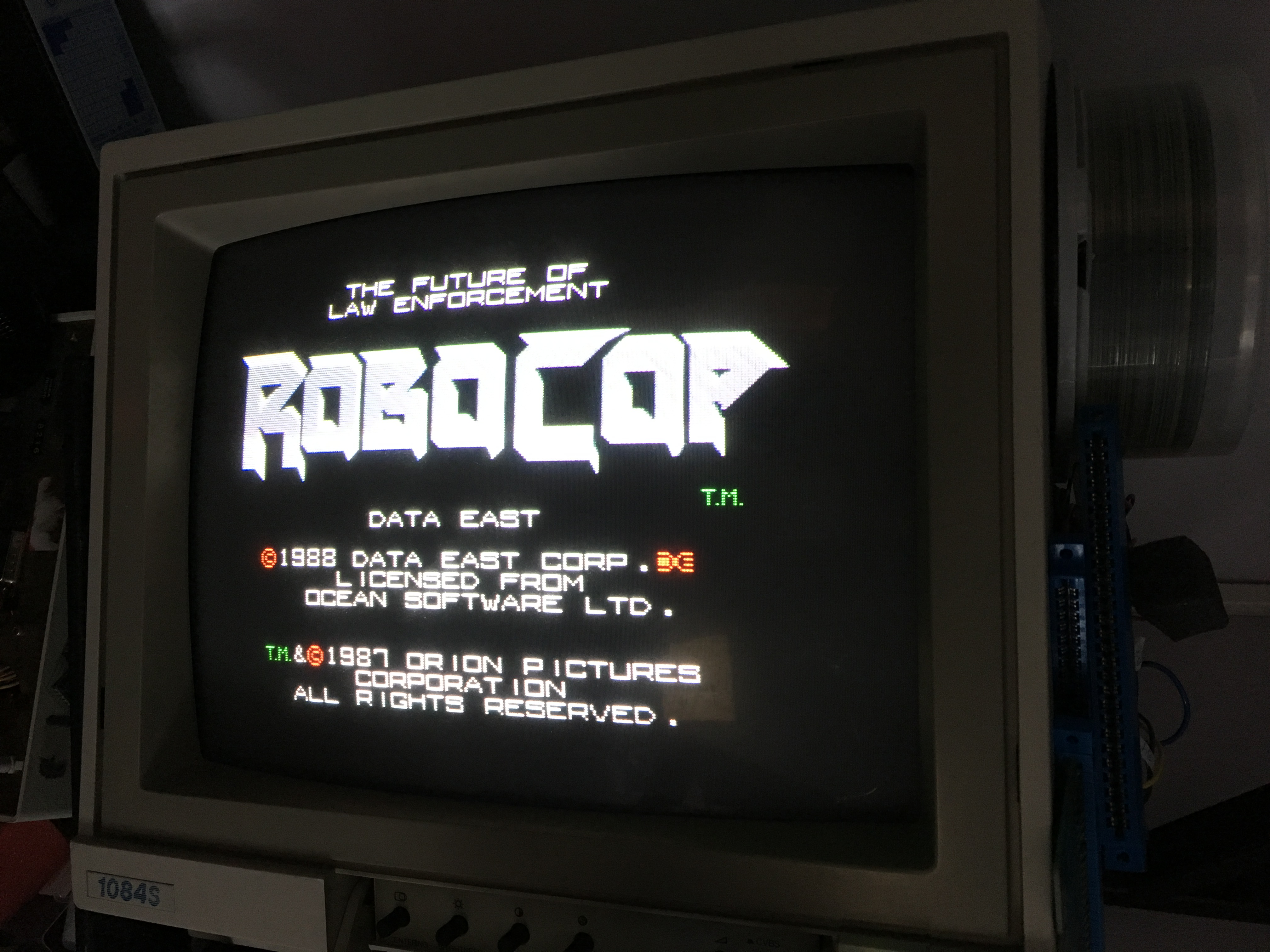
I got this Data East Robocop pcb from a friend that was totally dead.

I had more Data East pcb’s around so I could test the bottom ROM board with one of those CPU boards and it was also not working. So I started pushing the EPROMs in their sockets and after that the game booted up.

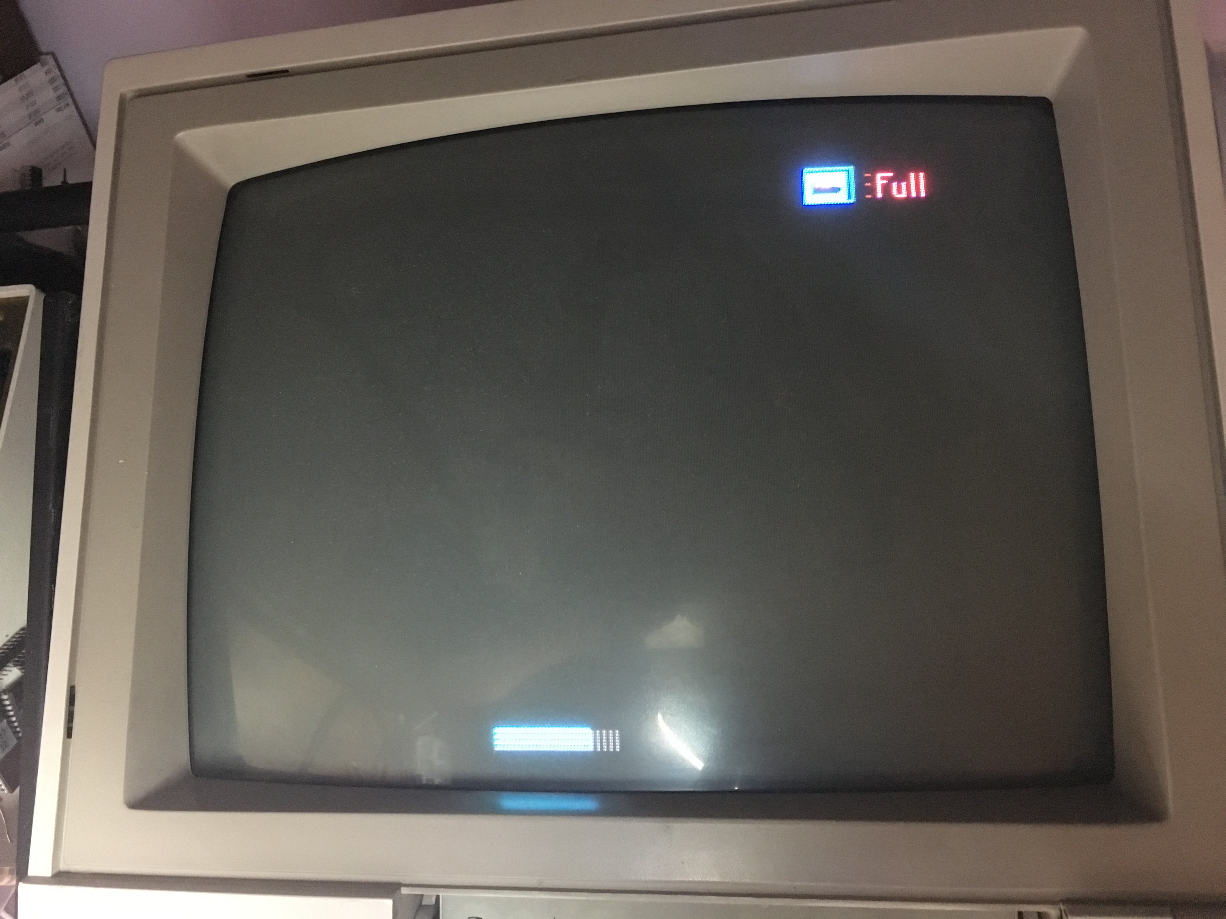
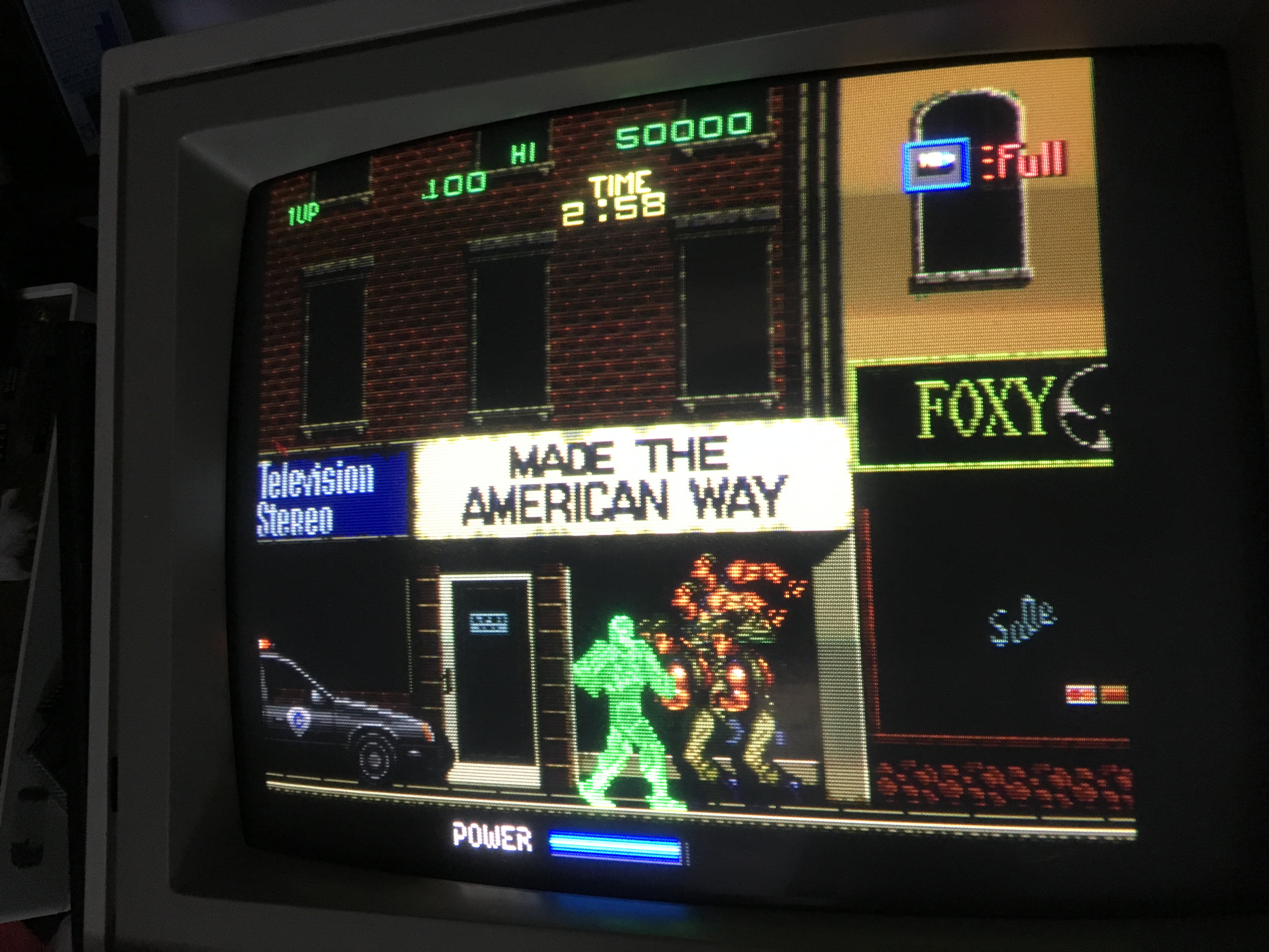
So now I tested the ROM board with it’s original CPU board and game booted but the screen was almost completely black apart from some graphical elements like the energy bar.

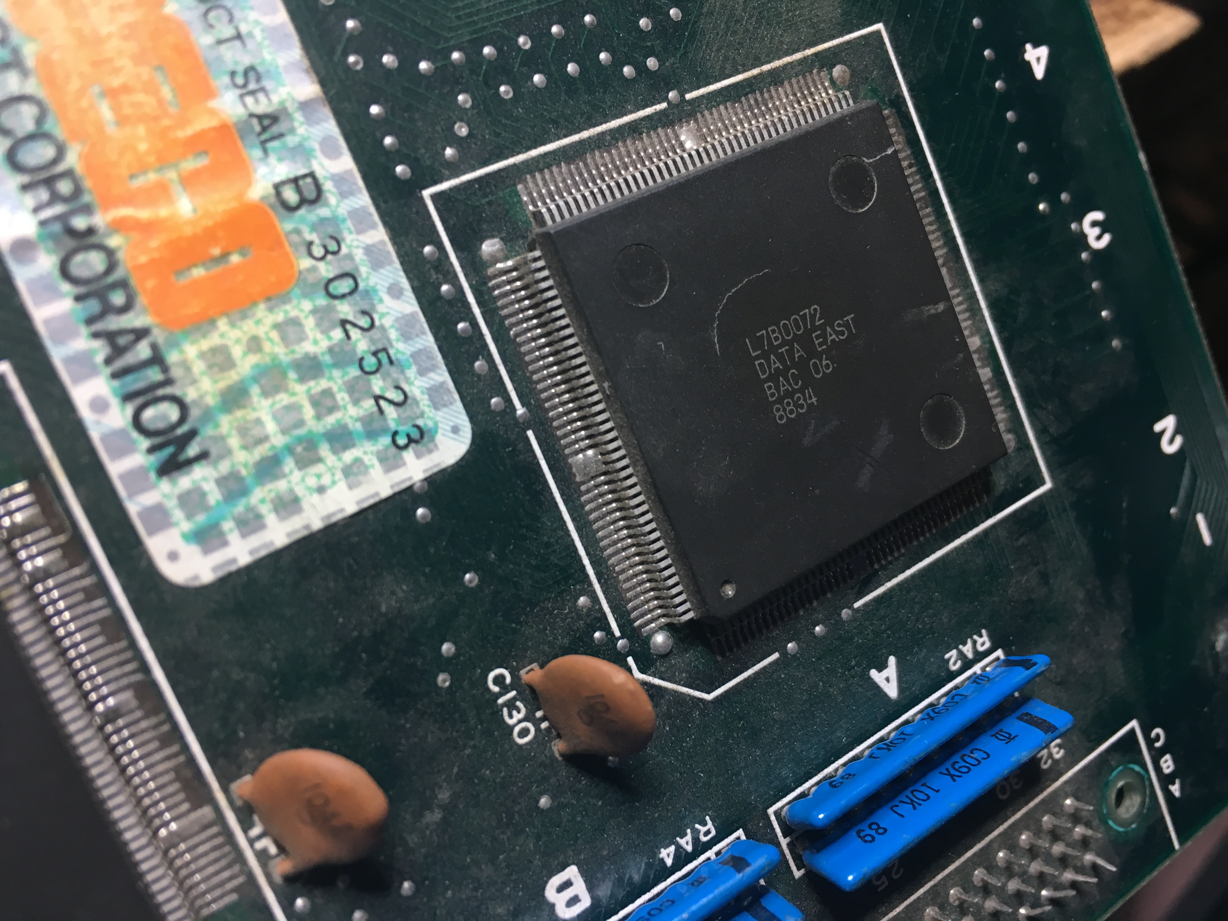
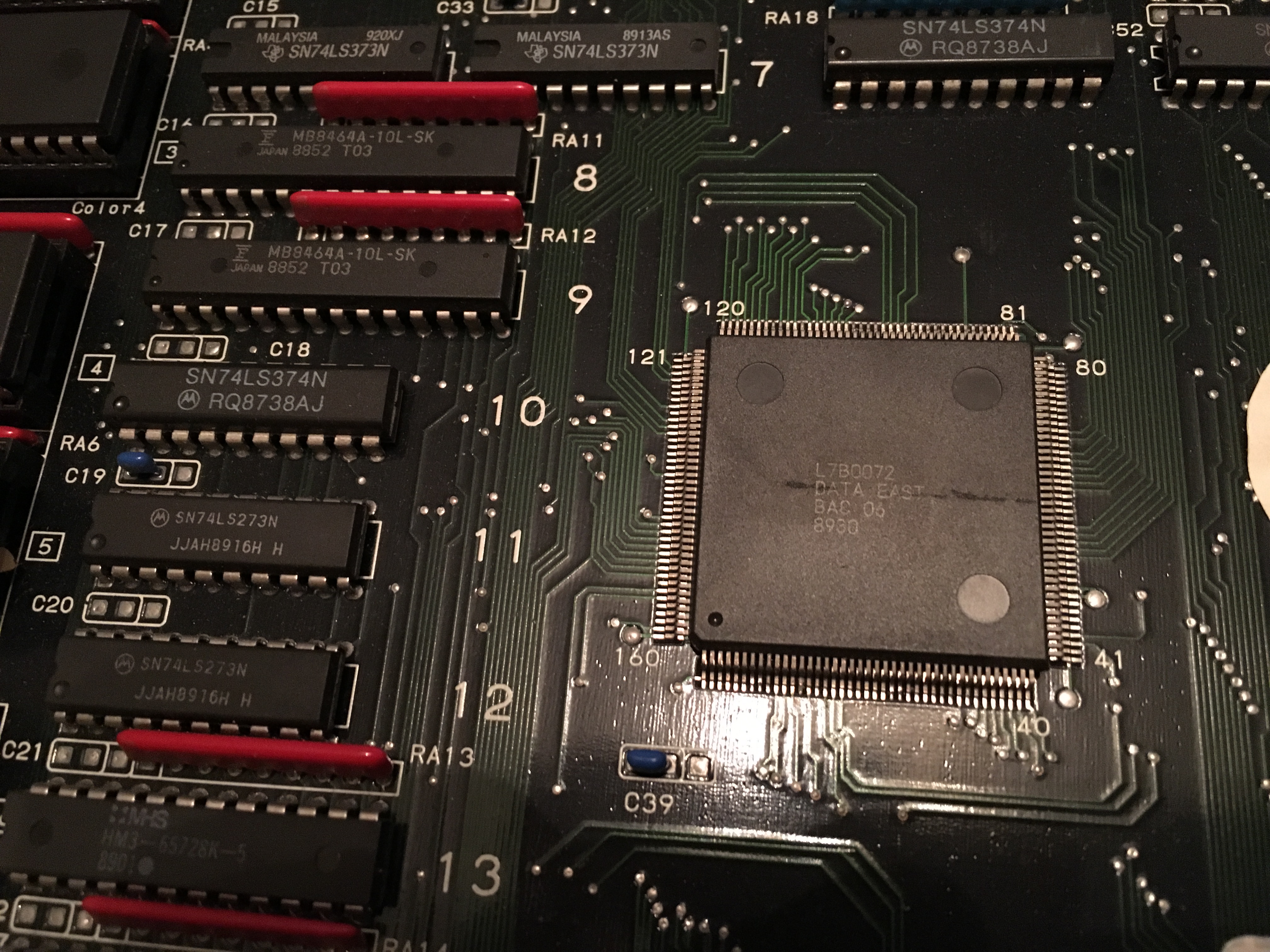
After visually going over the CPU board I found that one of the custom ASIC L7B0072 had a crack in the center of it.

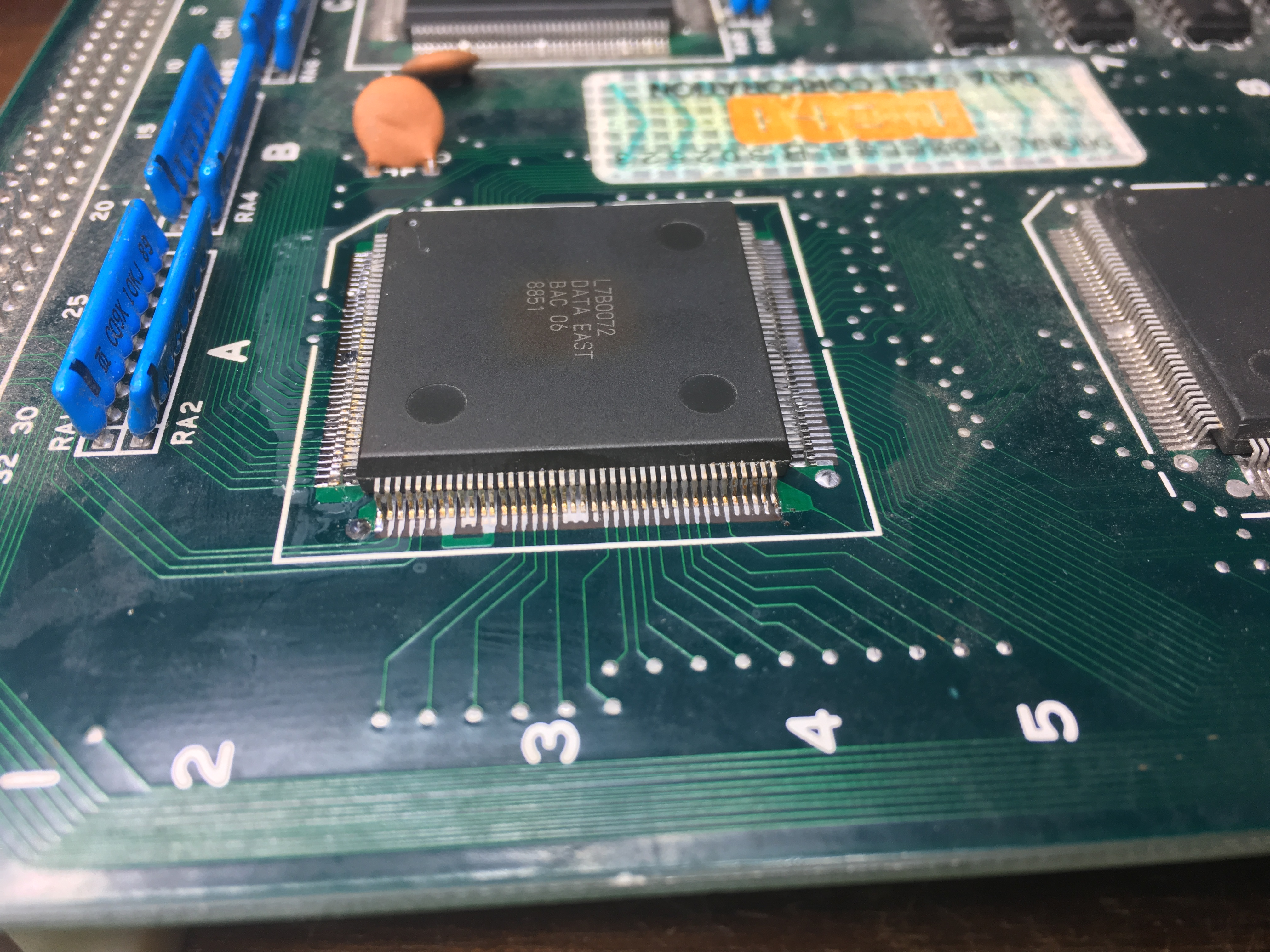
I had a broken Midnight Resistance board (not the previous repair) that had this ASIC, so I opted to transplant it over to the Robocop board.

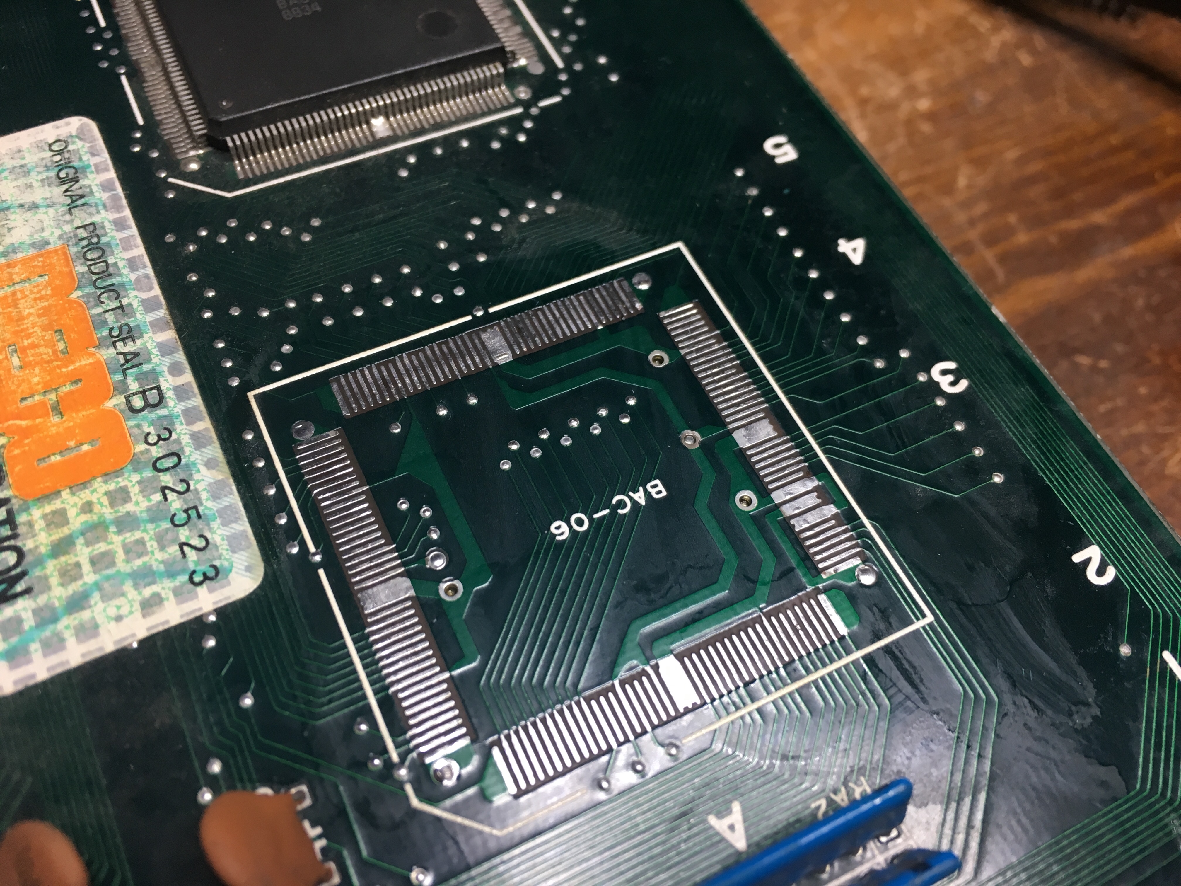
I noticed that the top of the ASIC had a brownish discoloration, but I didn’t know if it was toast or not, so I desoldered it with my hot air station and soldered it onto the Robocop board.

Confirmed that there were no shorted pins on the ASIC and booted the game, but unfortunately the transplant did not help. Some graphics appeared, but mostly scrambled characters and when coining up and pushing start, the game reset. (forgot to take a picture)

After having a conversation with caius (thanks again for all your advice) we opted to do another transplant but with a better looking ASIC.

Redid the procedure, hot air station to remove the ASICs and then soldering again and lo and behold, the game has good looking graphics once again ๐Ÿ™‚

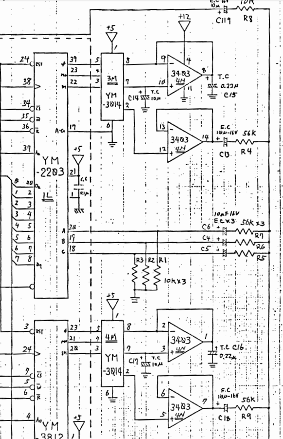
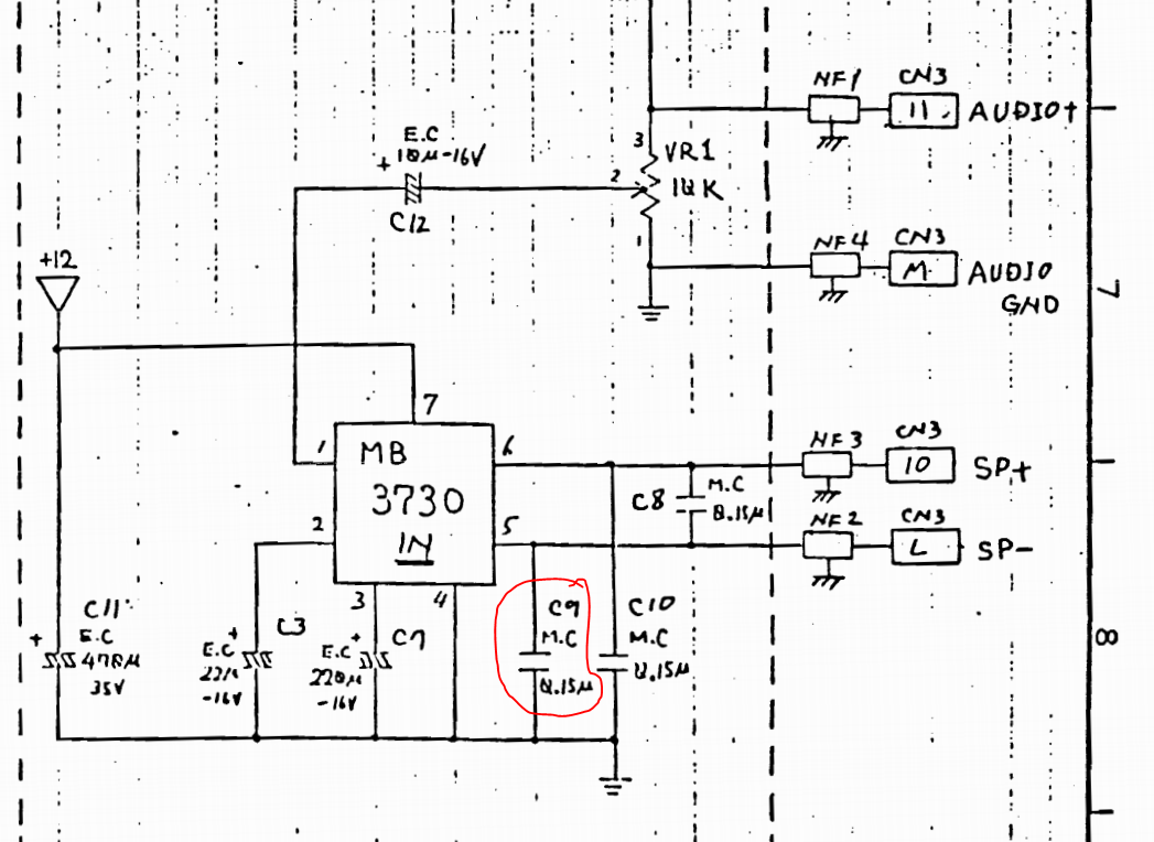
But I quickly noticed that there were no audio at all. Using my audioprobe I found that there were music been generated by the YM3014 at 4M and FX from the YM3014 at 3M and then going to the OP-AMP 3403 at 4N

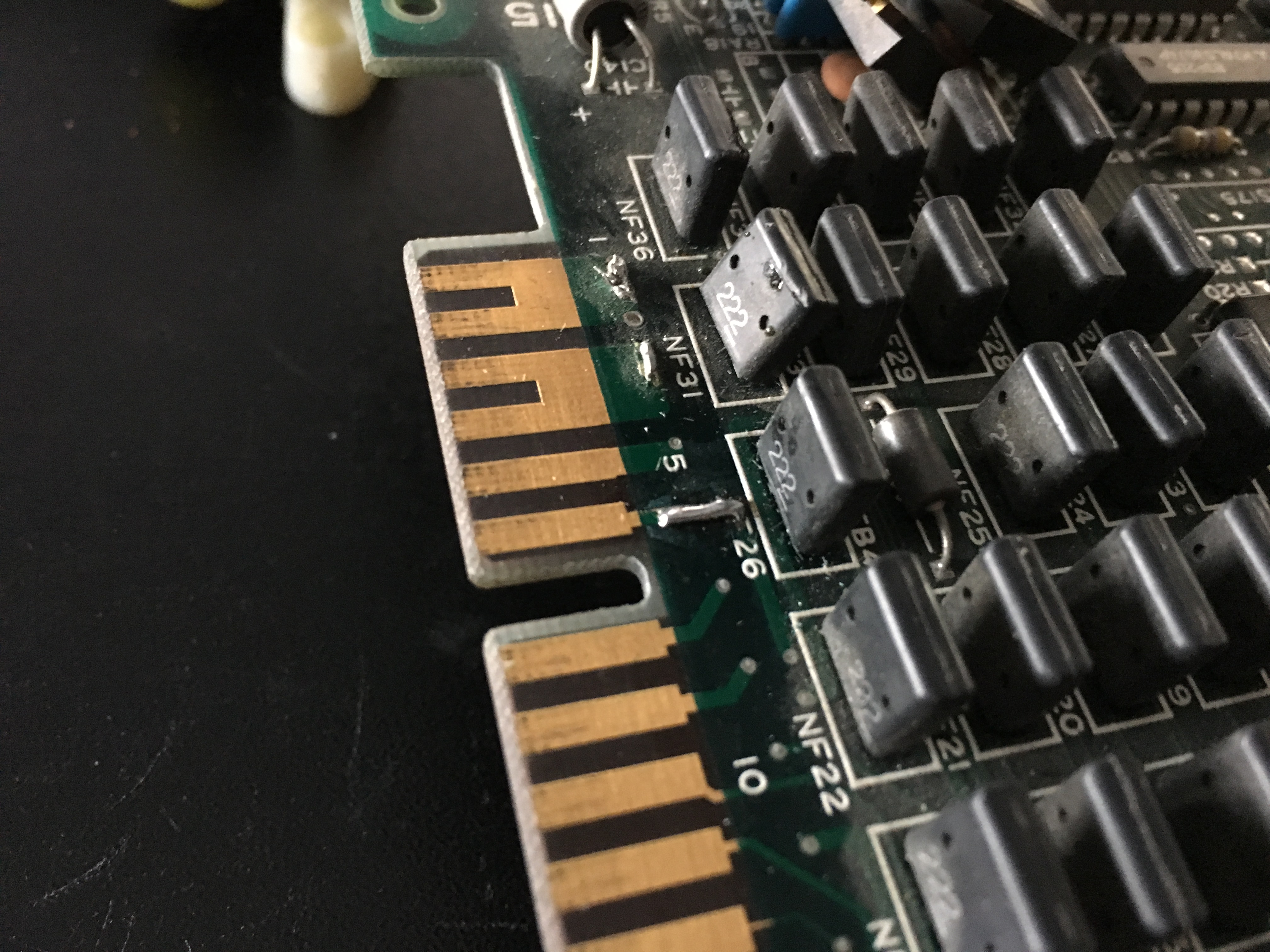
Nothing came out of the 3403, so I eventually found that there were no +12V input on pin 4 of the 3403. Checked the JAMMA edge and found a broken track. I guess that the operator had some form of voltage measuring device and somehow broke the track at some point. I soldered a little metal wire to bridge the gap and booted the game again.

Now audio could be heard for a short second and then silence again.

I eventually found a shorted capacitor atย 

After replacing the capacitor the audio was loud and clear again. Job done ๐Ÿ™‚


Midnight Resistance repair log

 PCB Repair Logs  Comments Off on Midnight Resistance repair log
May 082018
 

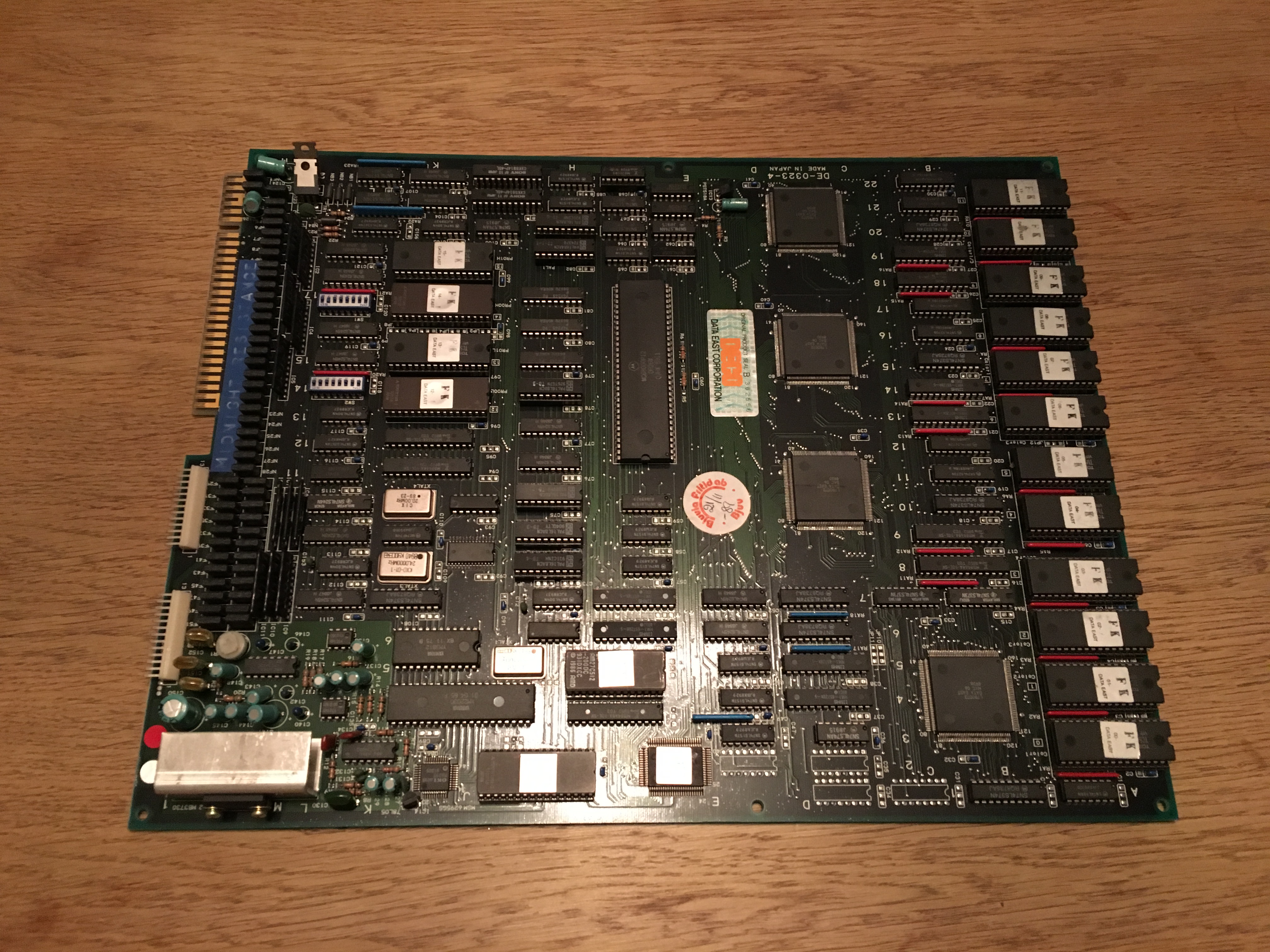
I got this Data East – Midnight Resistance pcb from a friend.

Heย said that he dropped a ground wire onto the pcb by mistake and he thought it touched the pins on one of the L7B0072 custom ICs.

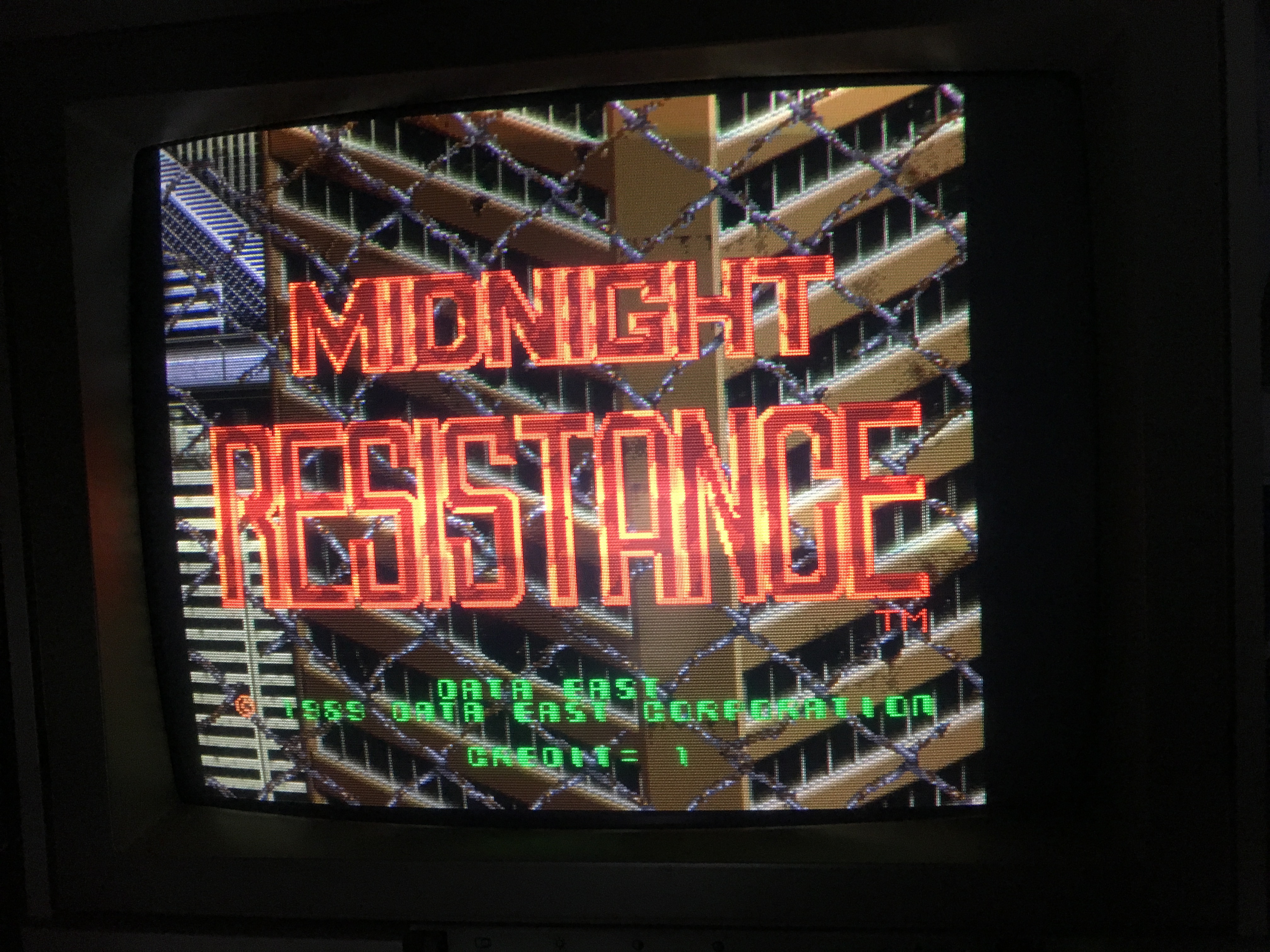
I booted the pcb and the game was running blind. Sounds and inputs was working fine, but a complete black image on the screen.

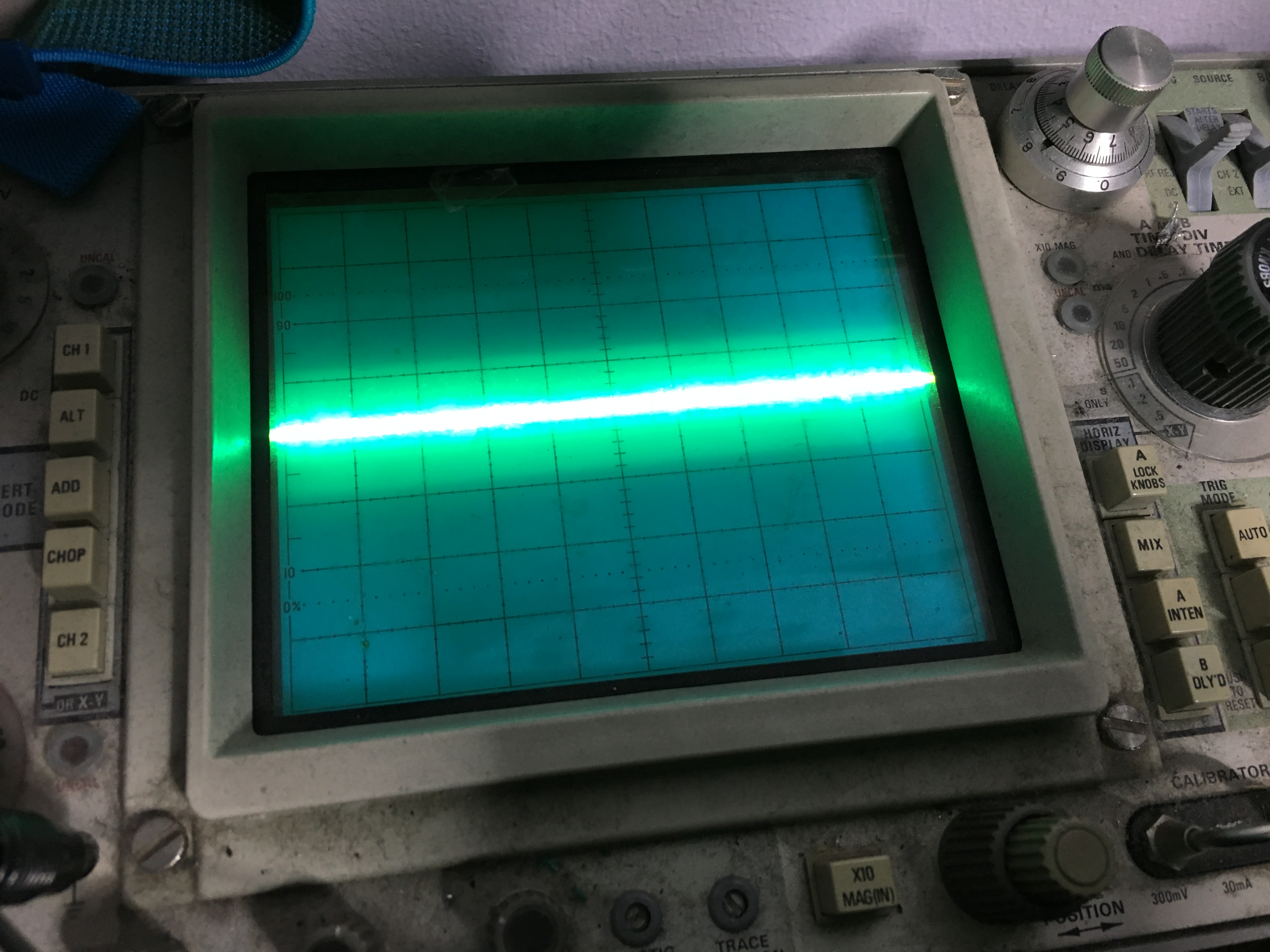
Been working on this hardware before, I knew that the palette RAM was located at J21 and J22, so I started checking their datalines with the scope

Hmm, zero activity

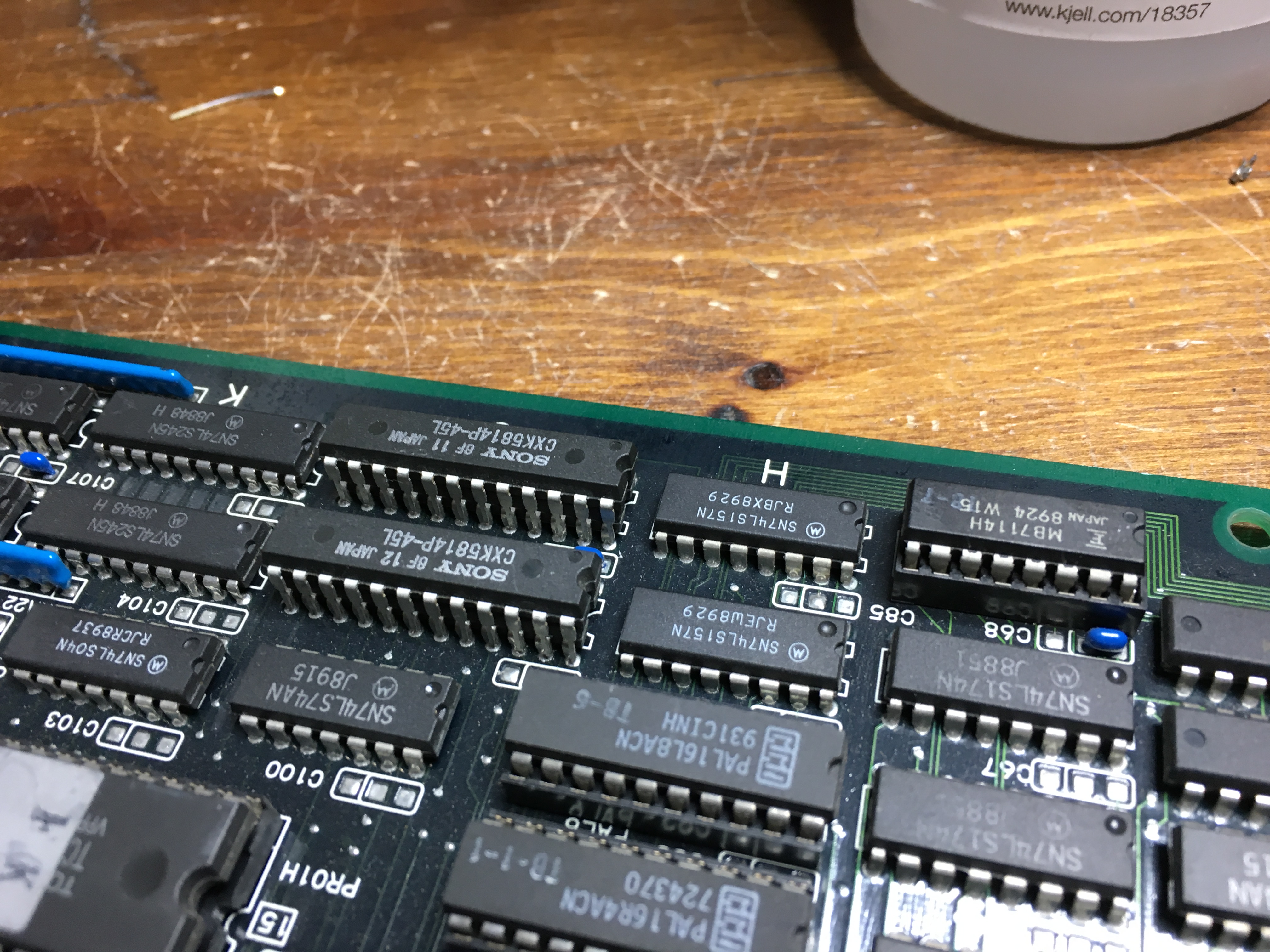
I then piggybacked a pair of new RAMs (6116 type) on top of the original RAMs

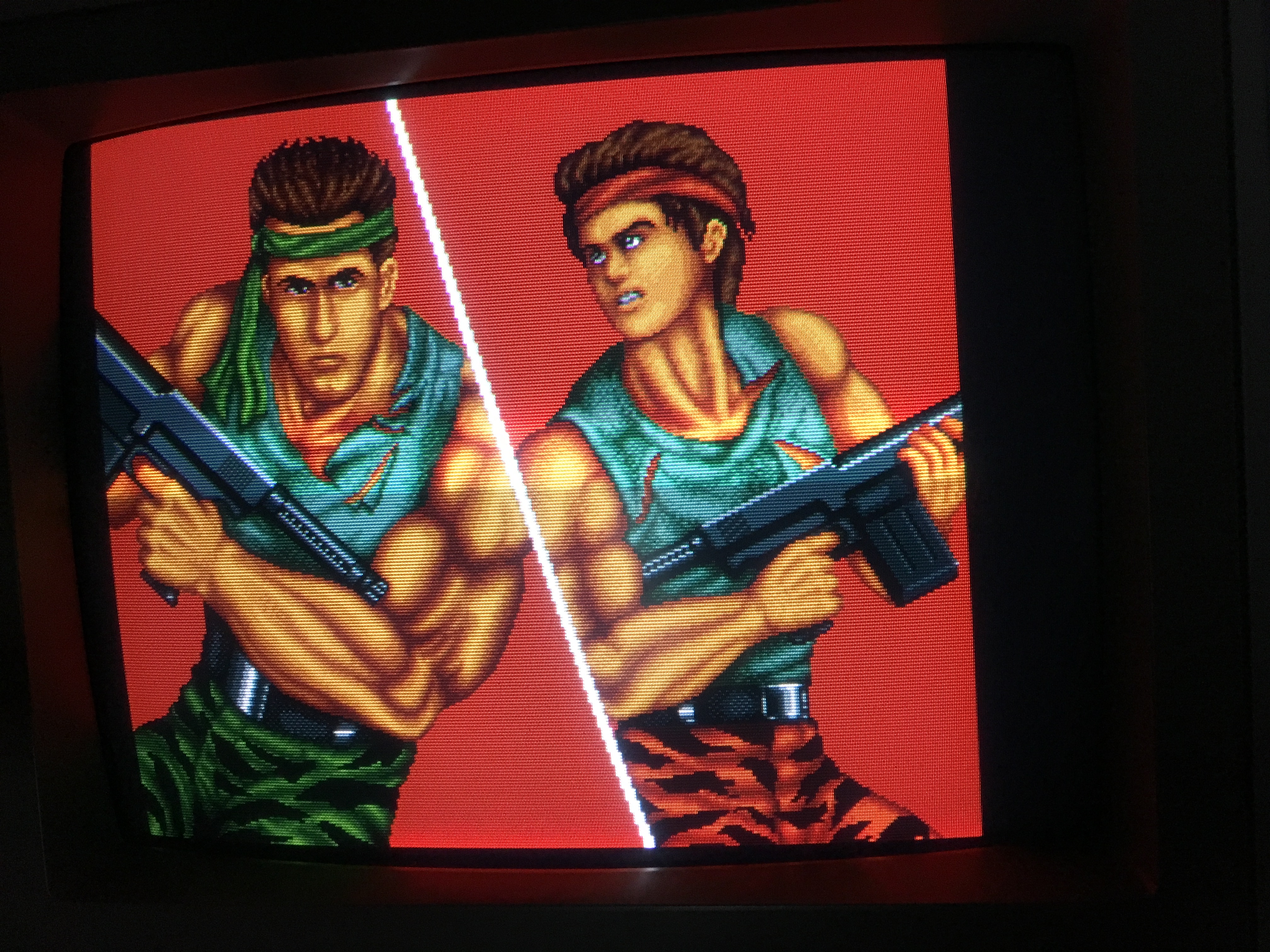
Voila, graphics are back ๐Ÿ™‚

I then promptly desoldered the RAMs

and soldered a pair of sockets in their place. And the new RAMs

Job done ๐Ÿ™‚