Corrado Tomaselli

No background in electronics. Learned everything by reading pdf books and expecially Video game logic Vol 1 by Atari and in general early Atari and Williams arcade manuals

Haunted Castle repair log #5

 PCB Repair Logs, Repair Logs  Comments Off on Haunted Castle repair log #5
Nov 252017
 

I got this board for my collection as untested from an arcade operator

Board was the typical Konami pcb manufactured in Italy ( I believe Electronic Devices had a deal with them to import the pcbs and populate certain chips in Italy).

You regognize these boards because they have sound z80 made in Italy , soldered eproms and cheap sound potentiometer

Later on, beginning of 90s they started to put also general “E.Devices” stickers on eproms in place of Konami ones, but at least the eproms were socketed

Back to this board, it booted and the graphic was OK but there was a continuous metallic sound all the time.

Ruled out DAC and OP AMPS because usually when these fails, you have at least either FM or samples working, I started to probe the sound circuit logic following the schematics.

I noticed that the commands from the main CPU were correctly sent to the sound section but as soon as the Z80 had an INTERRUPT request, the CPU didn’t aknowledge it and blocked itself

In particular:
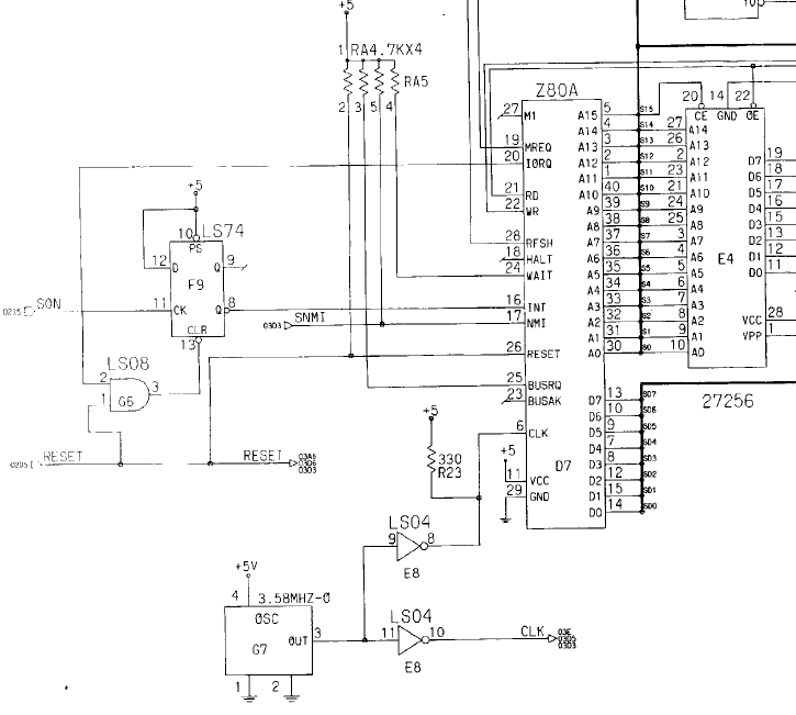
 

Signal IORQ didn’t go low, thus making the INT signal from the 74LS74 always LOW.

I proceeded to desolder the Z80 and tested it on another game with a socketed CPU and it confirmed to be bad.

While soldering the same Z80 by NEC used on proper Konami assembled boards, I also changed the sound potentiometer with an original Konami taken from another scrap game.
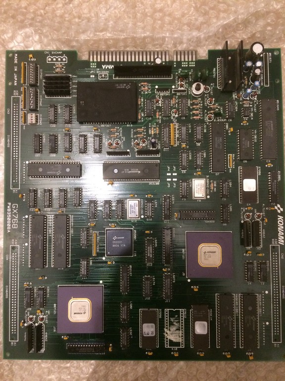
 

Game was fixed without any other issues.

Pac-Mania repair log #2

 PCB Repair Logs  Comments Off on Pac-Mania repair log #2
Nov 092017
 

I bought a faulty Pac-Mania mainly for spare parts but I gave him a chance and tried to repair it

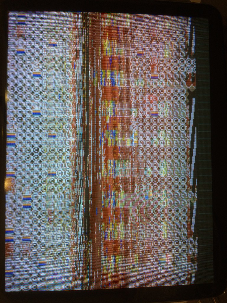
The game was missing sound roms, after replacing them, game booted and you could play but the screen was totally a mess.

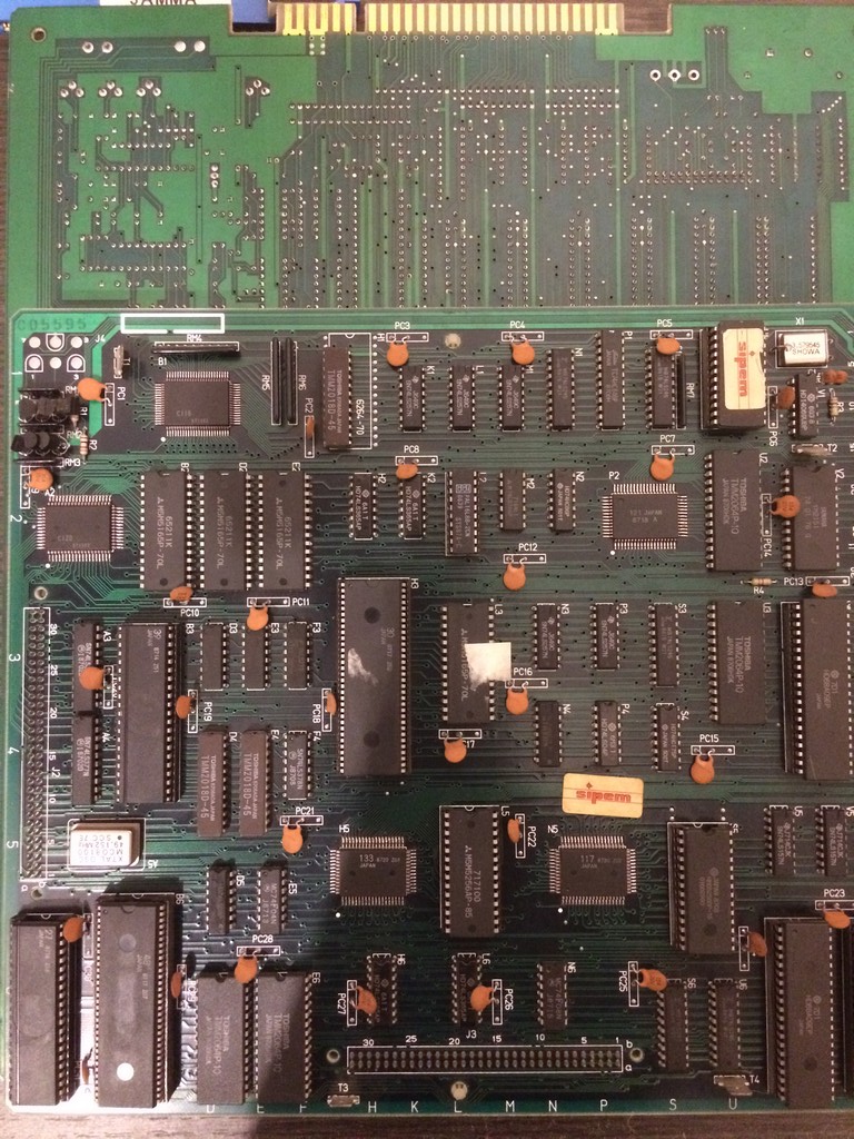
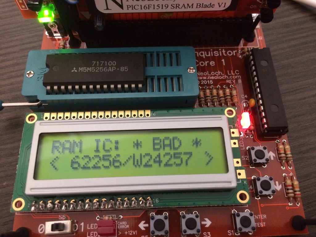
After some blind testing I started test all socketed custom chips and rams against new ones and I eventually found the culprit

in the “text” ram @L5!

It was so bad that it totally covered the screen with junk graphics

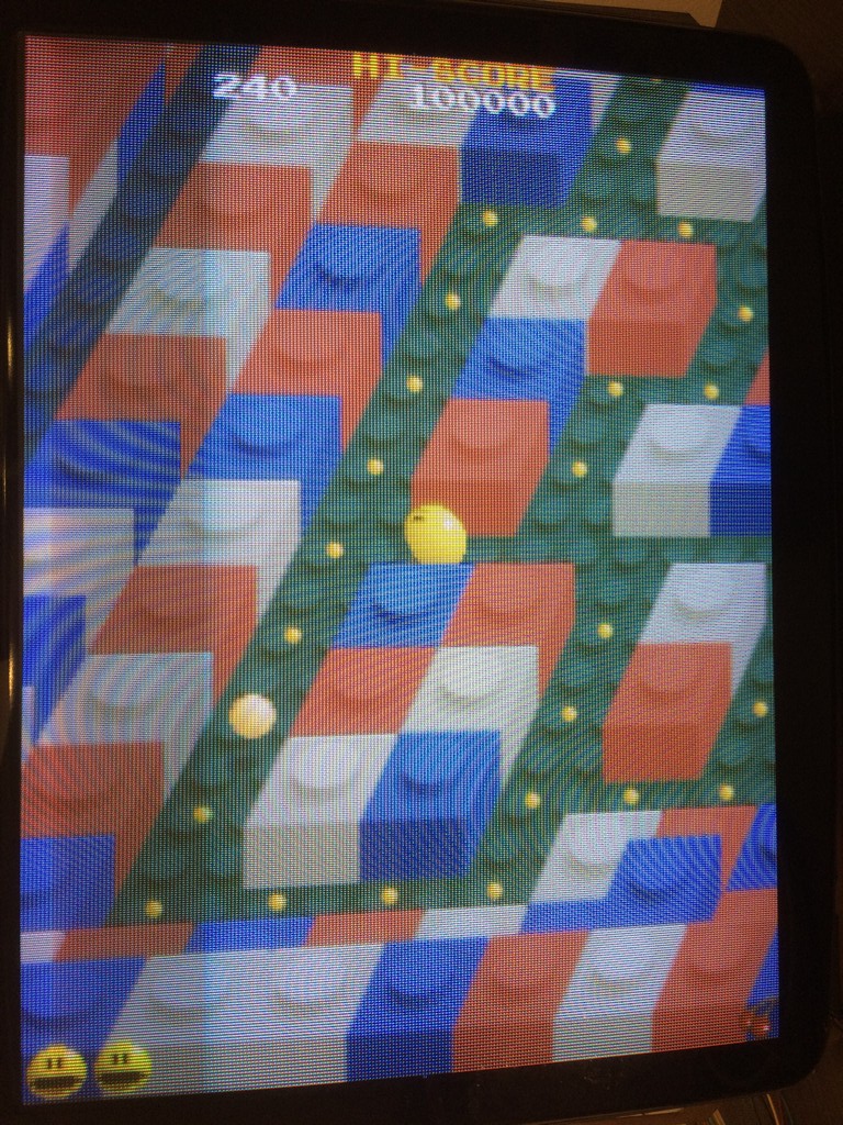
Replacing it fixed the game 100%

Pacland repair log #1

 PCB Repair Logs  Comments Off on Pacland repair log #1
Nov 092017
 

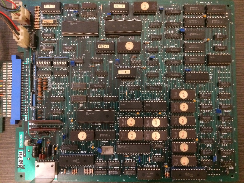
Got this Pacland, Sidam version, in mint conditions  for a repair

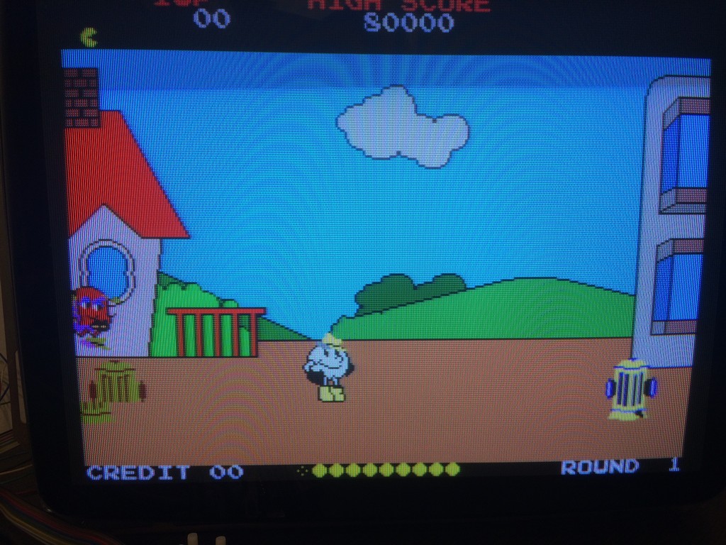
The game had some color bitplanes of the sprites shifted to the left as you can see from this pic

The sprites are handled by CUS29 and there are two 2149 rams connected.

Piggybacking a good 2149 ram on top of the one @3T restored good colours

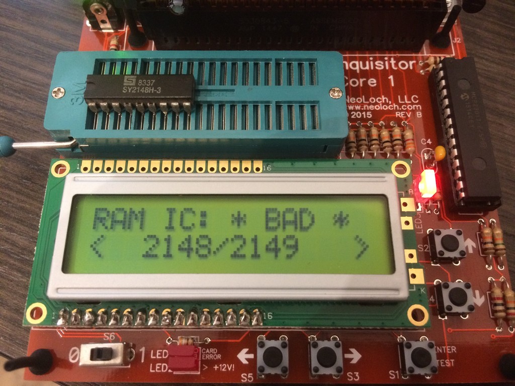
Testing it out of circuit confirmed it was bad

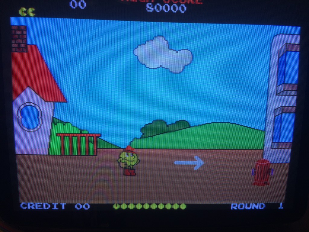
The game had no other faults and was 100% fixed

Megazone repair log #2

 PCB Repair Logs, Repair Logs  Comments Off on Megazone repair log #2
Aug 102017
 

Got this faulty pcb for my collection


Game was resetting over and over right after the first stating screen without even the possibility to see the diagnostic screen “RAM ROM OK”

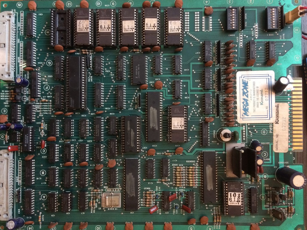
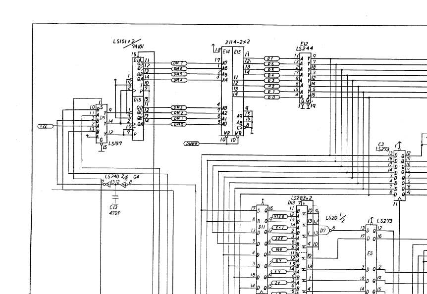
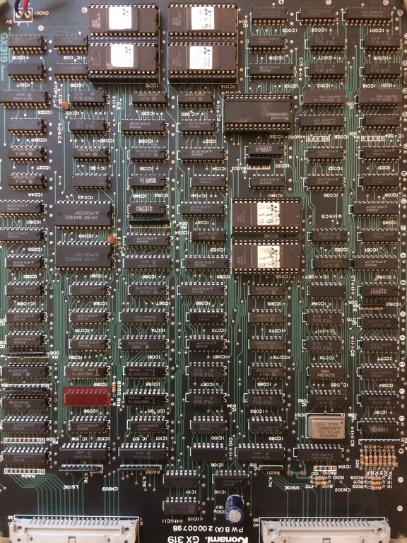
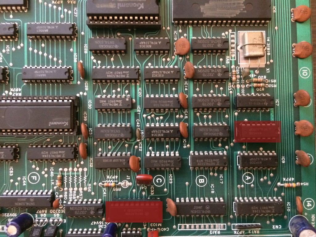
The code was running and the watchdog was triggered by some event which I eventually found in a faulty 2114 SRAM @E15 on the video board


Marked in red on the actual pcb:

After changing it, the boot process went on until it displayed RAM and ROM OK but it reset again just before screen with the white grid.

At this time I was complete blind , missing any programming skills I couldn’t check what the code missed to go on.

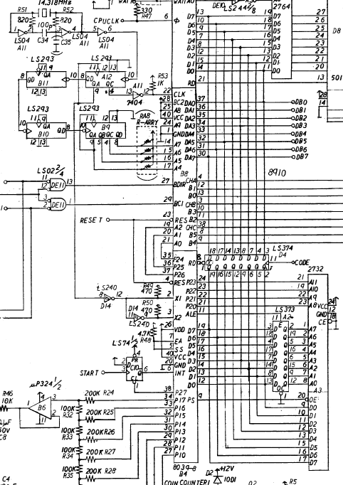
I had a suspect on the sound part and after checking the clocks on the 8039 MCU I noticed it was completely missing.

The oscillator was working correctly and from the schematics I could see that the clock for the 8039 and the AY is generated using some 4bit binary counters 74ls293, very difficult to find on other boards.


Probing pin 9 of 74ls293@A12 it was stuck high while on pin 10 I had the clock.

I proceeded to test it out of circuit but was tested good.

Not sure about the reliability of the tester, I found a Starforce boot which use one 74ls293 and I installed it in a socket on megazone.

Still reset and no clock from pin 9

The output of the IC@A12 goes to pin 8 of a 74ls240, therefore I decided to test pin 8 of IC @D14 against +5V and it gave me a short.

After changing it the game finally booted without any other faults


Jul 012017
 

These system boards from Namco has a common problem: SMD capacitors

These caps expecially the ones produced in the 90s are very unreliable and sooner or later will start to leak

On my boards there isn’t one that has the ESR in a good range.

On Namco system NA ( Emeraldia, Tinkle Pit, Super World Court) or NB ( Point Blank, Nebulas Ray), the problems you will face are sound related ( low sound or scratchy ), on ND system ( Namco Classic Collections), the SMD caps are used also for the RGB amplifier and in addition you will get colour problems.

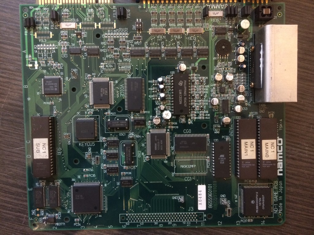
I will take as an example a Namco Classic Collection I just finished to repair and which had all the problems coming in about one week of intensive use after a while in storage.


First of all it started to have trails on the RED component of the image.

The system uses a common RGB amplier LM1203 which for example is used on the majority monitors neckboards

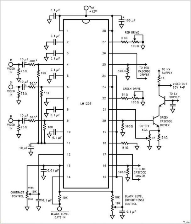
Here are the usual circuit taken from the schematics of the LM1203:

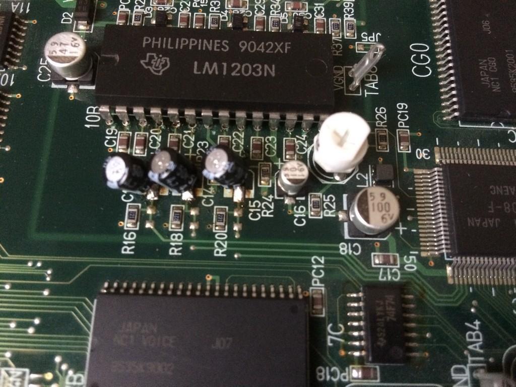
As you can see , on the inputs of each colour component you have to place a 10uF cap.

Namco engineers decided to use a 4,7uF but I tested and there are no differences between the two values.

So, if you have colour quality problems on your Namco Classics Collection pcbs, first thing is to recap the RGB input section using commercial

electrolitic caps.


I am not a fan of brute force recap, so with my ESR meter I usually check all the caps and change only the ones that have a very out of range value.

As said before, after few days I get no sound for a while and after about 5 minutes, you could hear it coming up but very scratchy.

The amplifier got also really hot after a short time.

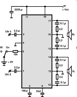
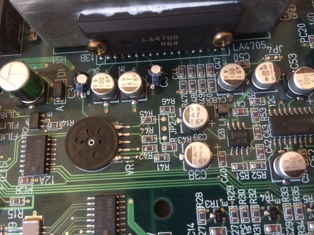
The system uses a LA4705 sound amplifier


I probed with the ESR meter all the caps and found out the both the small ones 2,2uF placed onĀ  IN1 and IN2 had a value of more than 99 ohms.

The other ones also were really not in the specification range but to get sound back it was enough to change the small ones.


As said the sound section of Namco system NA and NB is the same more or less, therefore if you start to have low sound and you don’t have an ESR meter,

change the 2,2uF, 47uF (33uF on the amp schematics) and 100uF one.