Corrado Tomaselli

No background in electronics. Learned everything by reading pdf books and expecially Video game logic Vol 1 by Atari and in general early Atari and Williams arcade manuals

Shoot Out repair log

 PCB Repair Logs, Repair Logs  Comments Off on Shoot Out repair log
Apr 172016
 

Got this game for a repair.

Game booted without problems but it was missing music and sound effects.

The amplifier was working correctly as I could hear the typical white noise coming out of the speakers.
Shoot2


Shoot3


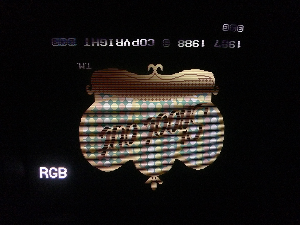
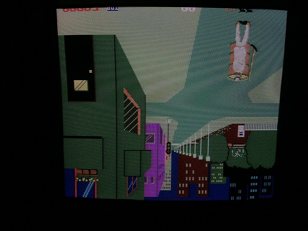
As you can see, the game is upside down and checking with Mame there is no flip dipswitch so unfortunately is one of the few horizontal arcade games which has the screen upside down (the other that I know is Athena from SNK).

Another thing you should have noticed is the copyright…..some smart italian arcade owner has hacked the original date from 1985 to 1987 to make the game looking newer….it’s unfortunately very common in Italy.

back to the real problem, I checked with my portable amplifier the input to the operational amplifier and there was no sound.

That meant that either the DAC was faulty of something in the sound circuit logic.

The DAC is a YM3014
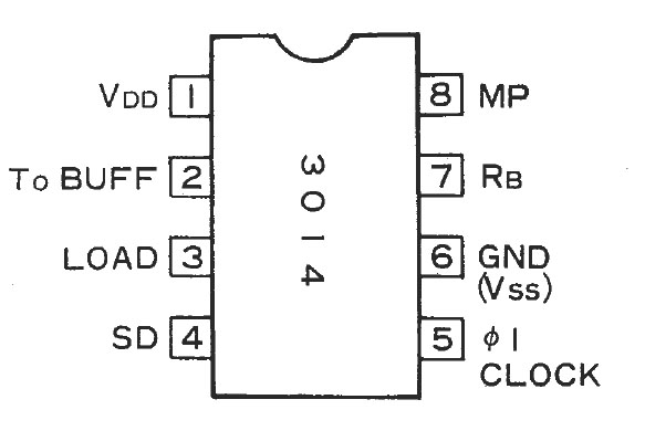
YM3014

The SD pin is the output of the YM2203 which is a digital waveform so normally you cannot check with an amp if the YM2203 is working or not.

The only thing you can hear is white noise but there is a trick:  compare the breaks between melodies (example, between coin up and start game), so the YM2203 should also stop orstart again to output signals.

With this trick I could confirm that the DAC was faulty.

Replacing the YM3014 with a good one fixed the problem as expected.
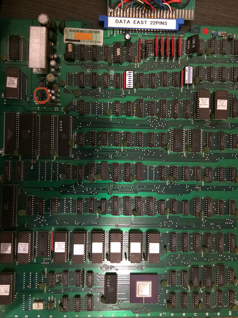
Shootout


Apr 082016
 

I bought this faulty pcb from ebay at a very cheap price.

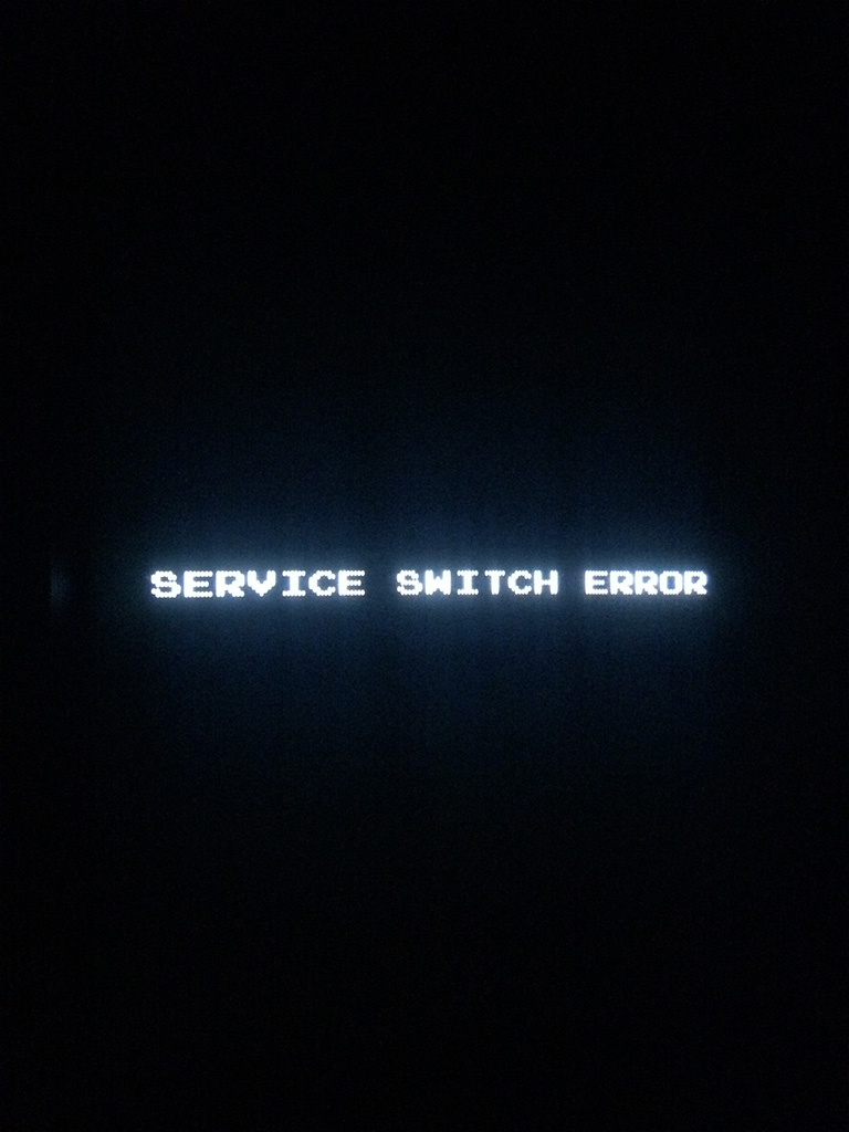
The seller mentioned that it had a “service switch error” and didn’t boot.

When I received it I could confirm the behaviour:

fh1

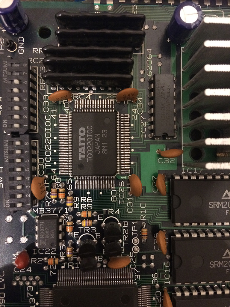
Several Taito games from late 80s to early 90s use a custom chip marked TC0220IOC which handles the inputs.

Looking at Final Blow schematics, the pinout is well documented so I started to check service signal which infact was always low on pin 36 of the custom chip


Capture


Before desoldering the custom chip, I checked the continuity of the Taito network resistor RRC4 (on Fighting hawk pcb) and I noticed that it had a very low resistance (less than 1Kohm)  to +5V in comparison to the other pins which had a 10kohm resistance.


fh2


So, for what it costed I proceeded to desolder the network resistor and see if the pcb booted.

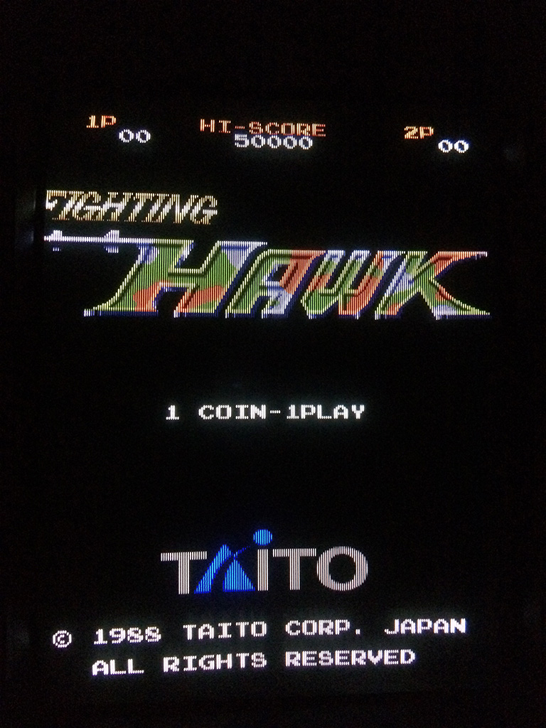
The game did  boot infact and it was a good sign, meaning that the problem didn’t come from the custom chip.

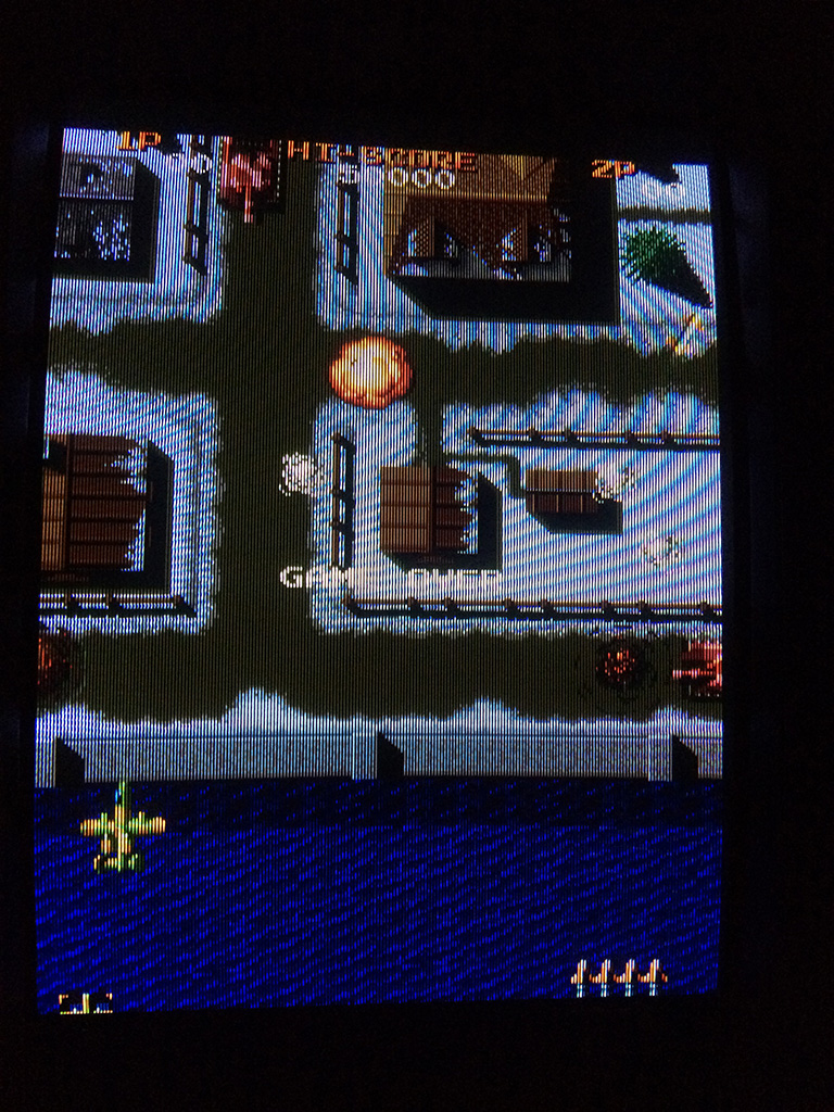
I found the same network resistance on a scrap taito pcb and the service switch was fixed but unfortunately the airplane was going up and left all the time and fired and thew bombs continuously.

After running the test mode, I noticed that all P1 and some P2 inputs were triggered!

To end the story short, I had to exchange ALL the network resistances except one to fix the game.

Looks like the game was connected reversed at one point and the network resistances probably protected the custom chip.

No further problems shown up


fh3

fh4

Super Qix repair log

 General, PCB Repair Logs  Comments Off on Super Qix repair log
Apr 052016
 

Got this game for a repair.

The pcb was missing one program rom and a graphic rom.

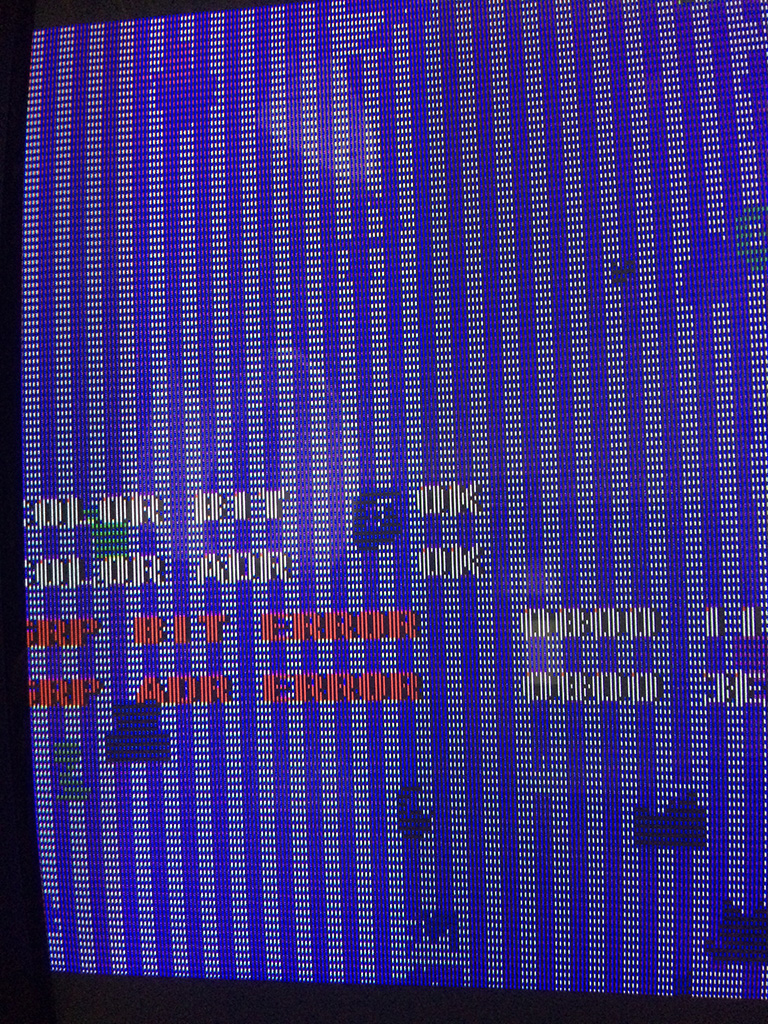
After checking which version was the game, I burned the correct eproms and I got this screen:

sqix1


A ram was reported bad but I didn’t know which one.

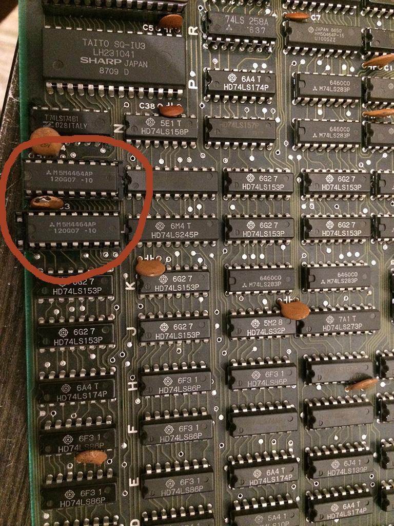
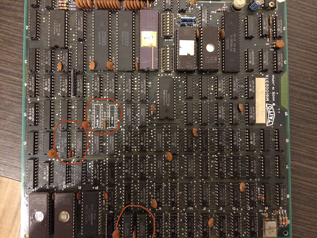
There were 2x 6116 SRAMS and 6x DRAMS type 4464.

When the error message is shown, the game get stuck in a loop and continuously checks the status, therefore I discovered that shorting pins of the DRAM @9L and 9M changed the hexadecimal value of the error.

With a logic probe the signals were oscillating but I decided to desolder them and put some sockets and test other drams I had to see if the problem changed or better could be solved.

Please note that all the DRAMS I had were taken from dead boards and I had no way to test them out of circuit.

So I proceeded to place the sockets and installed some drams chip and I got always different bits until finally it passed the POST test!

sqix2


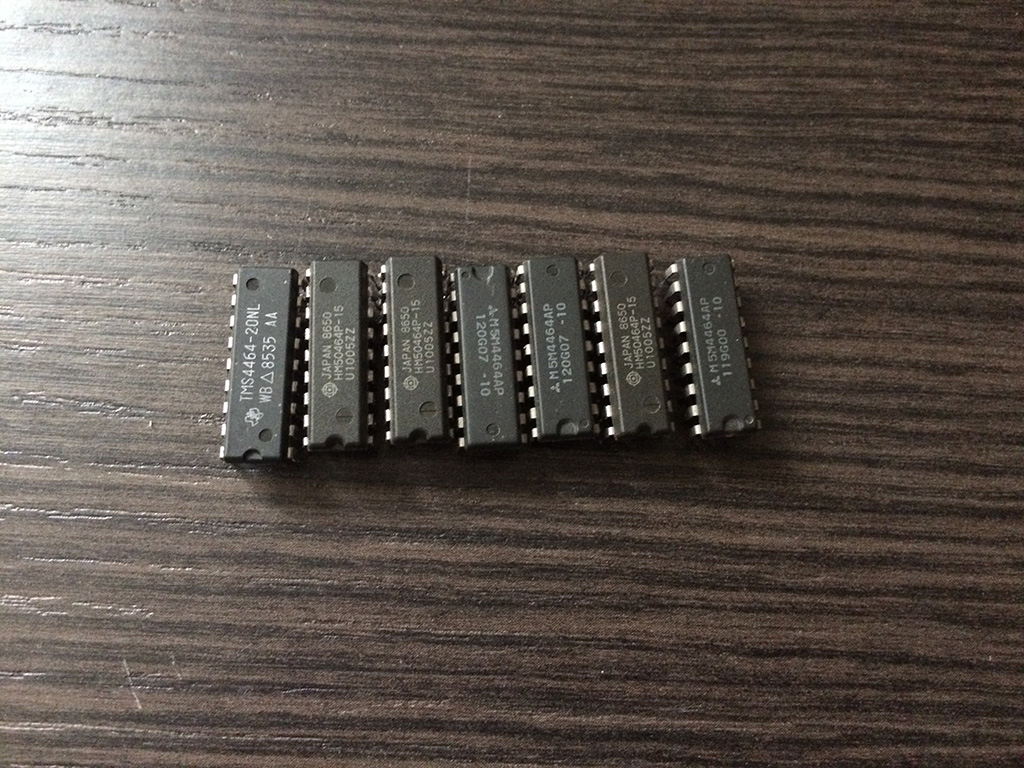
Turned out that I had several defective DRAMS chips and I took the chance to use Super Qix as a DRAM tester 🙂

Below are a collection of defective DRAMS, as you can see they are all from different brands…

sqix4


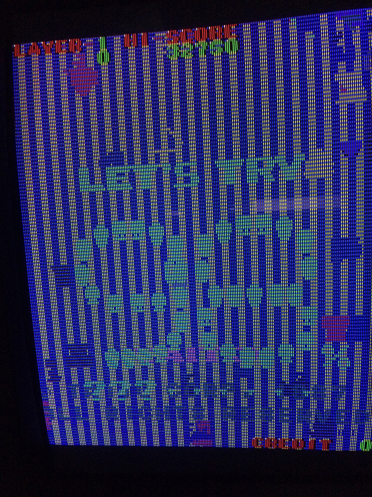
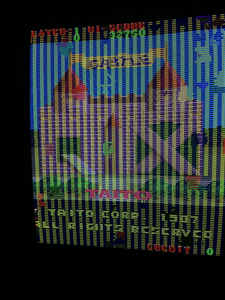
Back to Super Qix, , after changing the DRAMS, the game passed all the tests without further errors but I got this:

sqix3


The game had still the gfx messed heavily even if the ram test was reported good.

I shorted two pins of DRAMS @6S and 6R and I could see some better picture beneath the mess, so I decided to change also those two drams

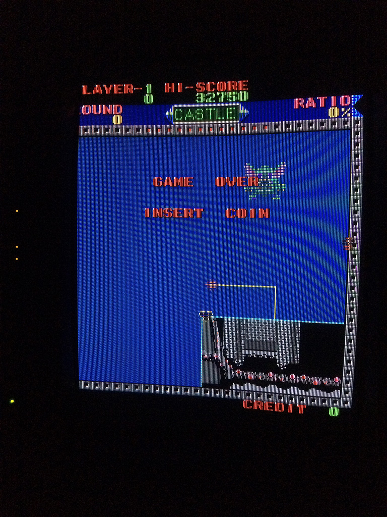
I started the game board without them in place and I got this:

sqix5


It was a good sign but to be 100% sure there were faulty I placed them back on the sockets @9L and 9M and I got again the error on the post screen!

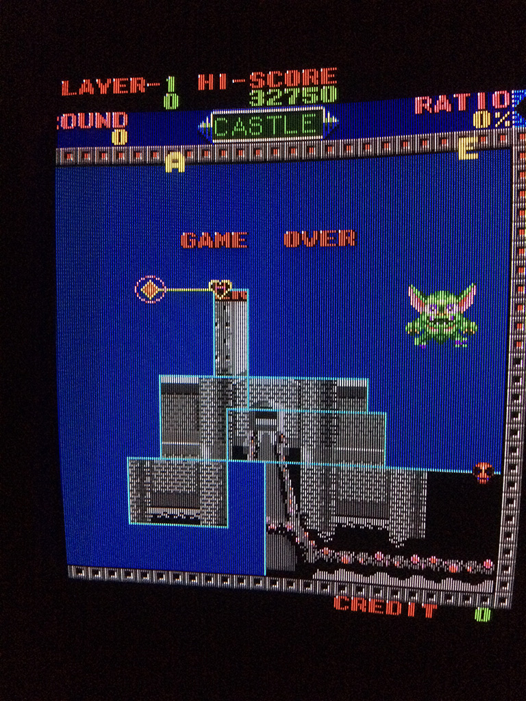
After placing two good drams I got this:

sqix7


Decided to go straight to the next two drams @5P and 5M and replaced without any further thoughts and…..

sqix8


Problem 100% fixed! Game had no further problems

So turned out that the game had all the 6 drams faulty but the game checks only 2 Drams out of 6x.

The other checks are done on the color sram and program sram.

sqix6

Pang repair log #4

 PCB Repair Logs, Repair Logs  Comments Off on Pang repair log #4
Apr 042016
 

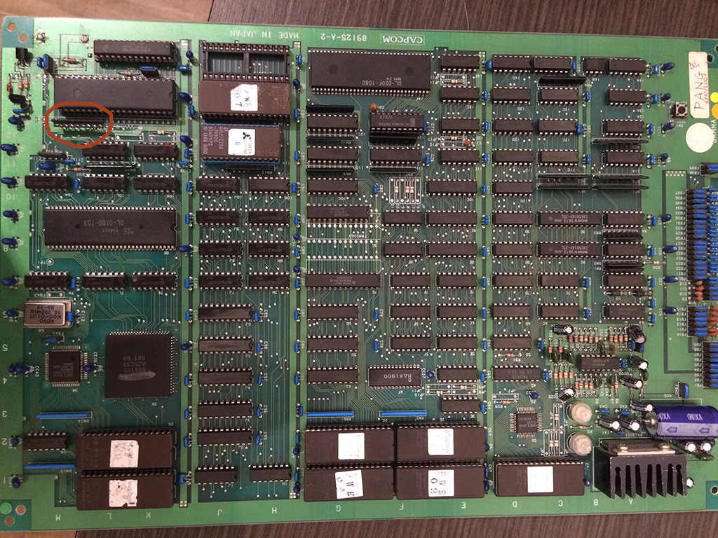
9 years ago I got a Pang for my personal collection. It was still with original battery and I carefully changed it with a new one because I didn’t like the wire wrap mod to desuicide it.

Unfortunately 1 year ago while testing the kabuki desuicider the game didn’t boot anymore, steady blue screen.

After testing succesfully the kabuki desuicider on another board it was clear my Pang developed a problem.

For more than a year I never managed to repair it until I got a Fluke 9010A which showed a problem on the z80 bus, the READ signal was not driveable.

I immeditely noticed that it had a very low resistance to gnd.

Near the Z80 there is a resistor network 4,7kohm.  the read signal was connected to a pin of this network which had only a resistance of 427ohm.

pang

I decided to desolder it and install a new one but the game didn’t boot.

I decided to let the game rest for some more time until one day I discovered that the game sometime booted , sometimes not but when it booted it crashed soon after.

Upon closer inspection I discovered that I soldered very loosy a pin of the network resistance!

After resoldering it better , the game booted without problems!


Ghosts ‘n Goblins (bootleg) repair log

 PCB Repair Logs, Repair Logs  Comments Off on Ghosts ‘n Goblins (bootleg) repair log
Apr 042016
 

Got this bootleg board for a repair.

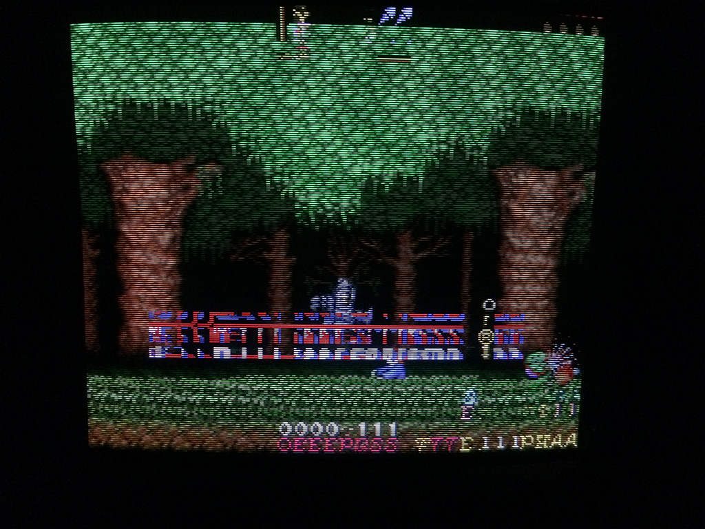
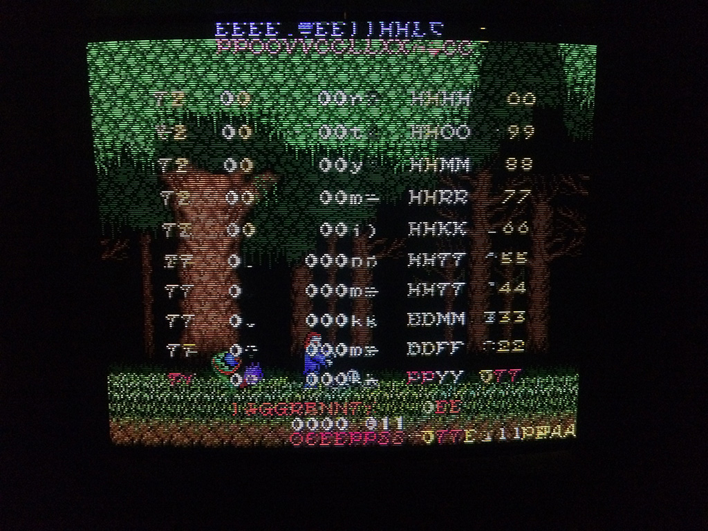
The game could be played with music and sound but had a problem on the text layer:

gng2

gng3


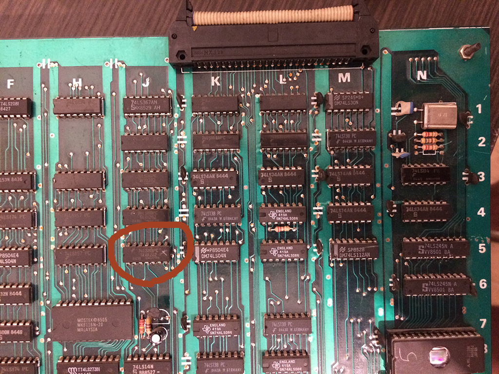
I started probing around until by shorting carefully  pins of some TTLs I found the circuit of the text layer on the upper board.

A 74LS86@5J had all its output in the grey area (2.2V):


gng1


Changing it with a new one solved completely the issue:


gng4

gng5