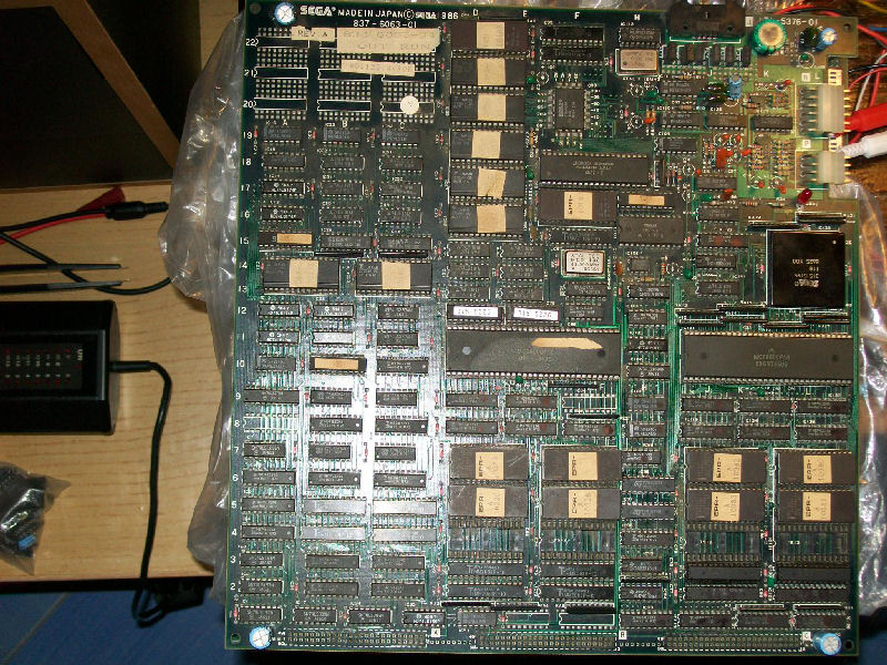
Another board from my friend ‘robotype’, this is the time of a genuine Sega Out Run:
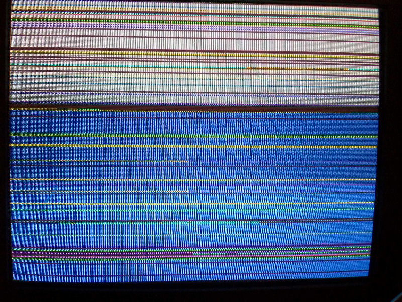
Once powered up I was greeted by a colored stripes static screen:
Since I already repaired an Out Run board with same issue I remebered that this is a symptom of active watchdog and infact this was confirmed by probing RESET and HALT pins on main 68000 CPU.I wanted to use my Fluke 9010A troubleshooter but due the presence of a custom memory mapper between main CPU and RAMs (which, indeed, generates dinamically the memory map on boot) I wasn’t able to do it.
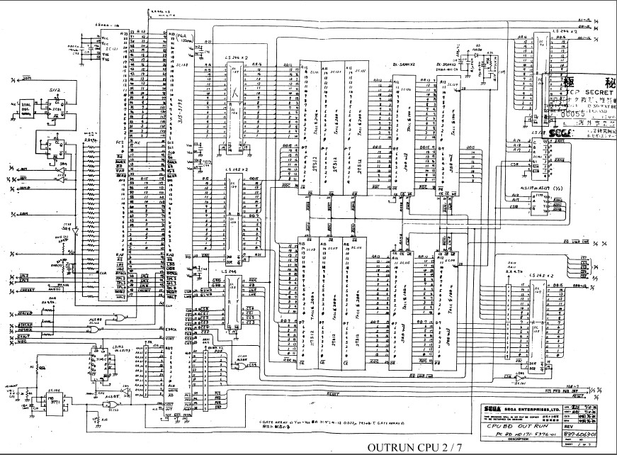
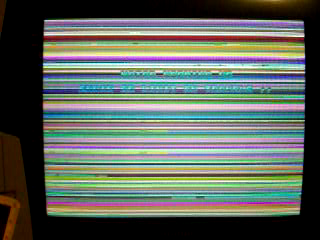
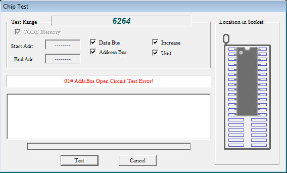
For first I read the four program ROMs and they were good.So I went to probe the CPU/RAM/ROM circuit and I found many CPU address lines tied LOW or HIGH.Piggy backing the two 74LS244 @IC136 and IC137 didn’t change nothing but when I did it on the two TMM2063 (6264 compatible) WORK RAMs @IC115 and @IC130 I got this screen in which I could descry the welcoming message of a successful boot:
This lead me to desolder the two RAMs which were confirmed as faulty from my tester
PAL UpdatesComments Off on Galmedes & Gaplus PAL dumps
May122015
Today it’s time to do some PAL updates.
Our finest contributor ‘coolmod’ sent in dumps of two unprotected devices (PAL16L8 and PAL20L8) from a Galmedes PCB (which runs on TAITO Bonze Adventure hardware). I took care of converting them to GAL format (both GAL20V8 and GAL22V10 conversions available of the PAL20L8) and he successfully tested them on his board. Thank again to him for this contribution.
Today I received a Gaplus PCB and tried both the MAME dump and the one on our database but neither worked so I dumped device (there is no part name but it should be a PAL16L8) from my board. Dump is tested and working in a GAL16V8 targeting device.
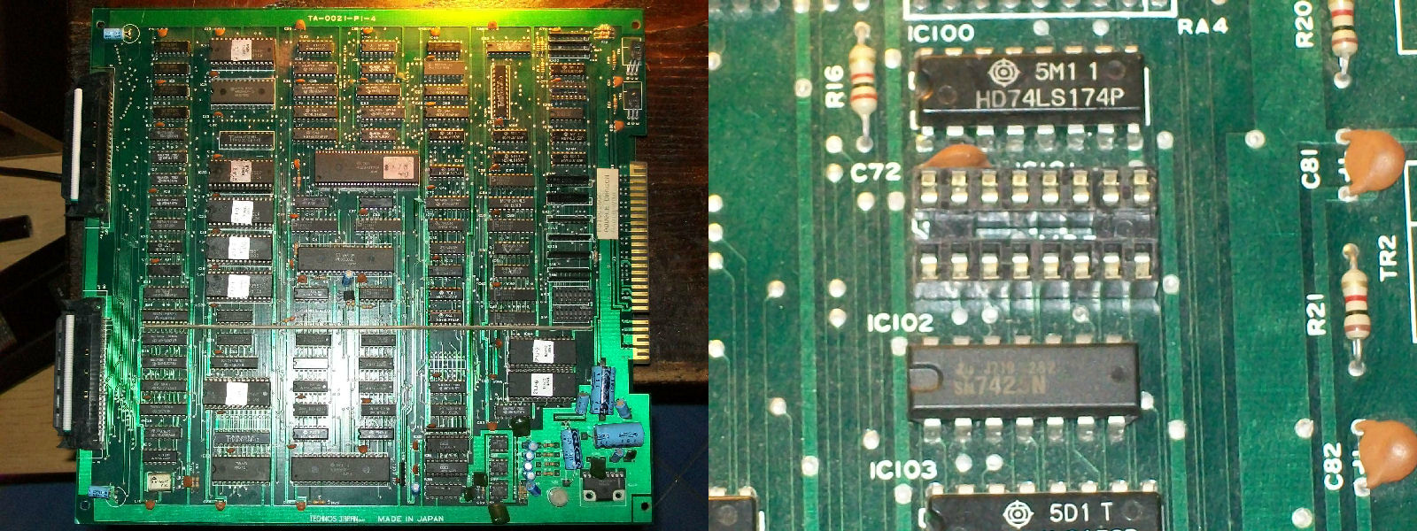
I had this PCB since many years, honestly I couldn’t remember when I got it or where.The only sure thing is that it was faulty.Condition was pretty good for a such ‘aged’ board but it was missing a BPROM @IC101 as you can see:
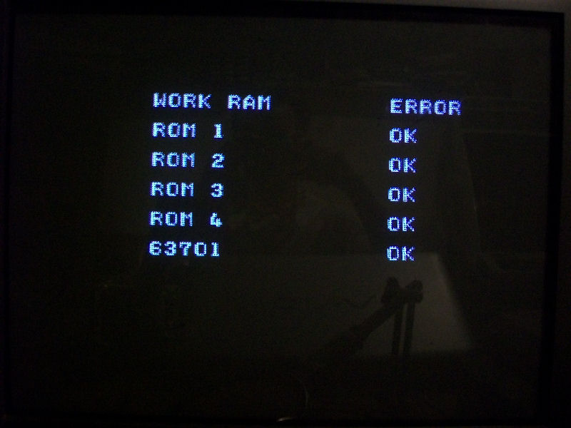
Original part is a Fujitsu MB7114, pretty impossible to find nowadays so I opted for a 82S129 which an equivalent one.After burned the device with the correct file supplied by MAME, I powered on the board and some times it got stuck on RAM/ROM TEST showing error on WORK RAM:
Other times it booted into game but sprites were missing, could not coin up, screen was unstable and speed was kinda accelerated.When I got this strange behaviours, the fist thing I check is the main CPU, in this case an Hitachi HD63C09.Probing it I found that PIN2 and PIN4 were stuck LOW, they are respectively the NMI and FIRQ interrupt lines:
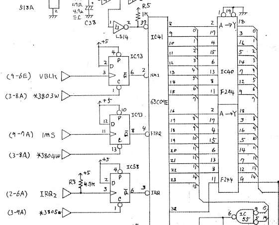
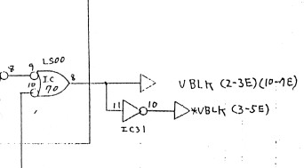
So this meant that CPU was undergoing a request of interrupt from external devices (an interrupt is a signal to the processor emitted by hardware or software indicating an event that needs immediate attention).As you can see from the above schematics these two signals are generated by a 74LS74 @IC73 so for first I went to check it and I found missing CLOCK and CLEAR signals input on PIN3 and PIN13 respectively.In particular CLOCK on PIN3 is the VBLANK signal and this is generated by a NAND gate of a 74LS00@IC70 on VIDEO board :
Comparing it in-circuit revealed it was faulty:
Once replaced it I got no more WORK RAM error and strange behaviours, game was playable but all sprites were missing:
This a common fault on all Double Dragon PCBs since object generation circuit is wide and made of many components (it occupies five sheets of the .PDF schematics).
So, following the schematics I checked this part of circuit and all was fine until I came across to this section:
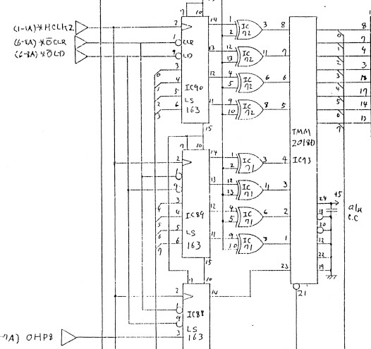
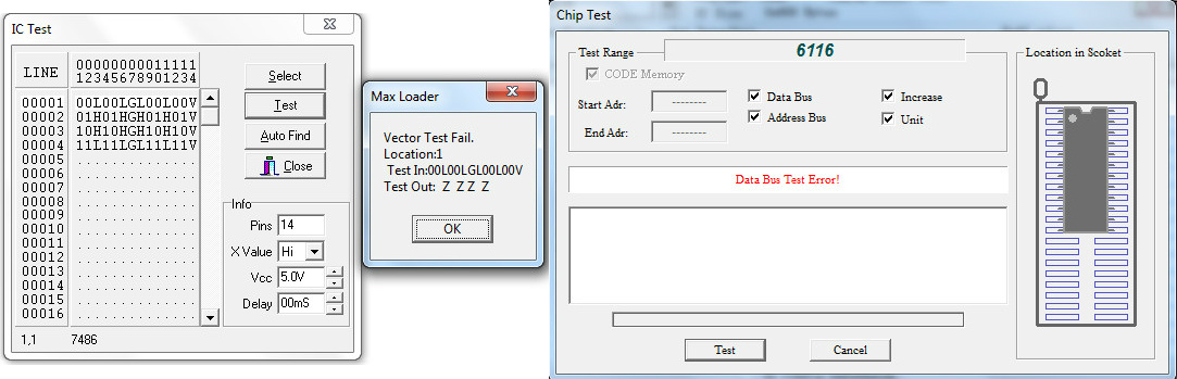
The 74LS86 @IC72 had stuck outputs and these are tied to some ADDRESS lines of a TMM2018 SRAM which had some silent DATA lines, too.So I prontly desoldered them and they failed once tested out-of-circuit:
I thought my job was done but I was wrong since this improved the sprites but not fully restored as they still missed some lines symptom of missing DATA:
So I kept to check the OBJECT circuitry until I come across the TMM2018 SRAM @IC20 which had four silent DATA lines (PIN14-PIN17).I piggybacked it and magically all sprites were restored:
PCB 100% fixed and another one preserved!
Just a note for future reference : there are five TMM2018 (6116 equivalent) sprites RAMs and they are @IC73, @IC81, @IC84, @IC120 and @IC7 on VIDEO board.
This will be a long repair log so if you have better to do, come back later… 🙂
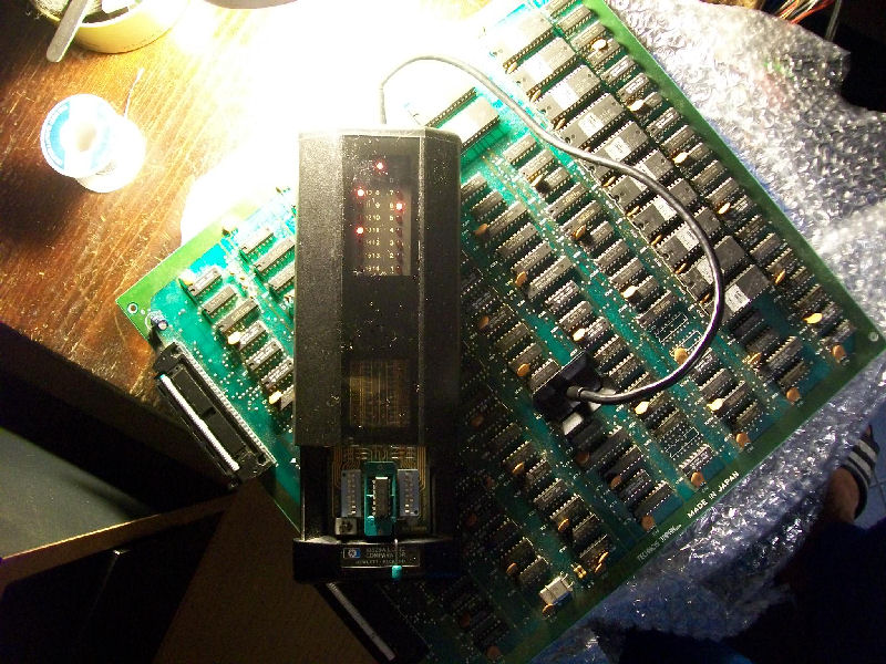
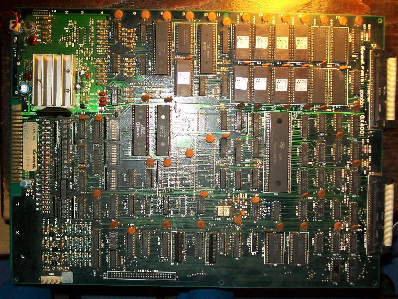
Got this Konami Nemesis PCB from my friend ‘robotype’.Board was in very good condition despite its age (it’s 30 years old)
but bought from him as not working and infact it was just so :
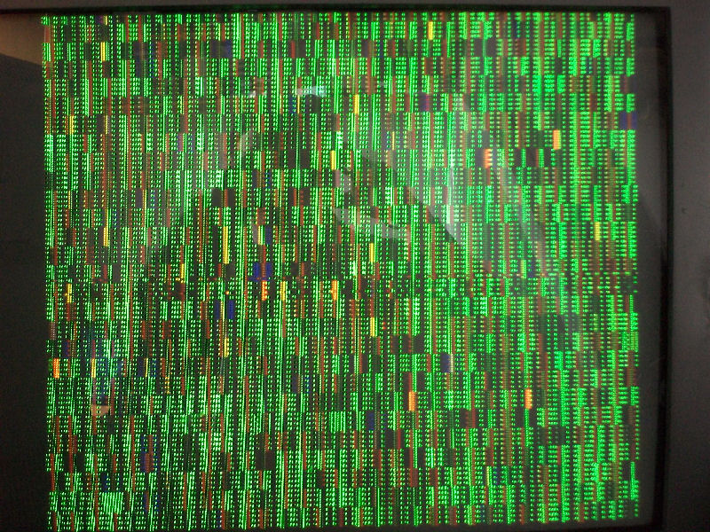
All I got was this static scambled screen.First I checked main CPU 68000, it had random activity on DATA/ADDRESS bus) but, worst thing, it was was burning hot to the touch!
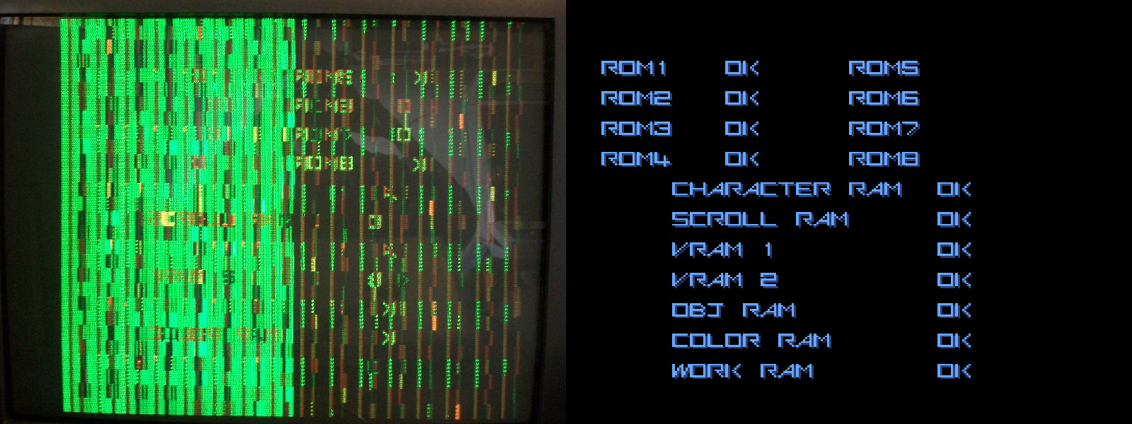
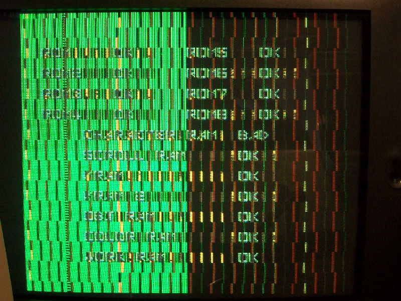
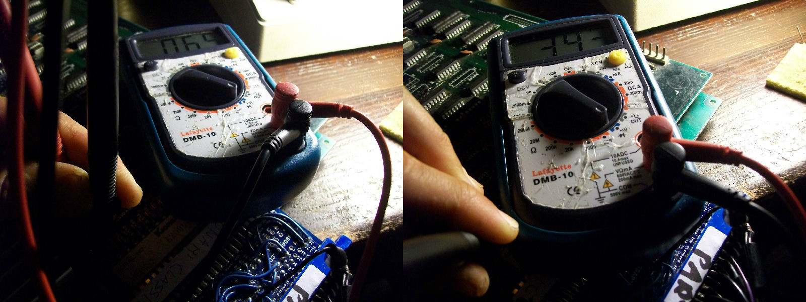
So I decided to replace and socketed it (faulty one showed a resistance of only 65 Ohm across VCC and GND).With a new CPU fitted situation was a little improved but still some address lines were stuck LOW or HIGH.Fired up my Fluke 9010A with a 68000 POD and I could successfully test the WORK RAMs (four MB8464).So there was someting that drove the address lines.Piggybacking the 74LS244 @17L on CPU board I could descry the RAM/RAM initial check and comparing with a good one from MAME, ‘CHARACTER RAM’, ‘VRAM 1’ and ‘VRAM 2’ were apparently reported as bad:
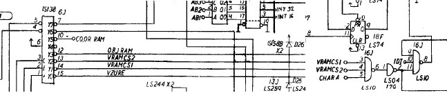
Probing the VRAM 1 ( TC5533 @ A15 and C15) and VRAM 2 (TC5533 @ D15) on VIDEO board revealed that their enable lines were stuck HIGH.These signals are generated by a 74LS138 @6J which I tested good with my HP10529A logic comparator then are routed to a 74LS10@16J :
this gave me troubles on PIN8 when compared with a good reference chip.Testing it out-of-circuit confirmed it:
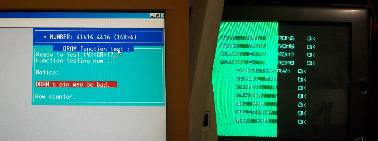
Replacing it cleared the VRAM 1 and 2 error but still CHARACTER RAM was reported as bad:
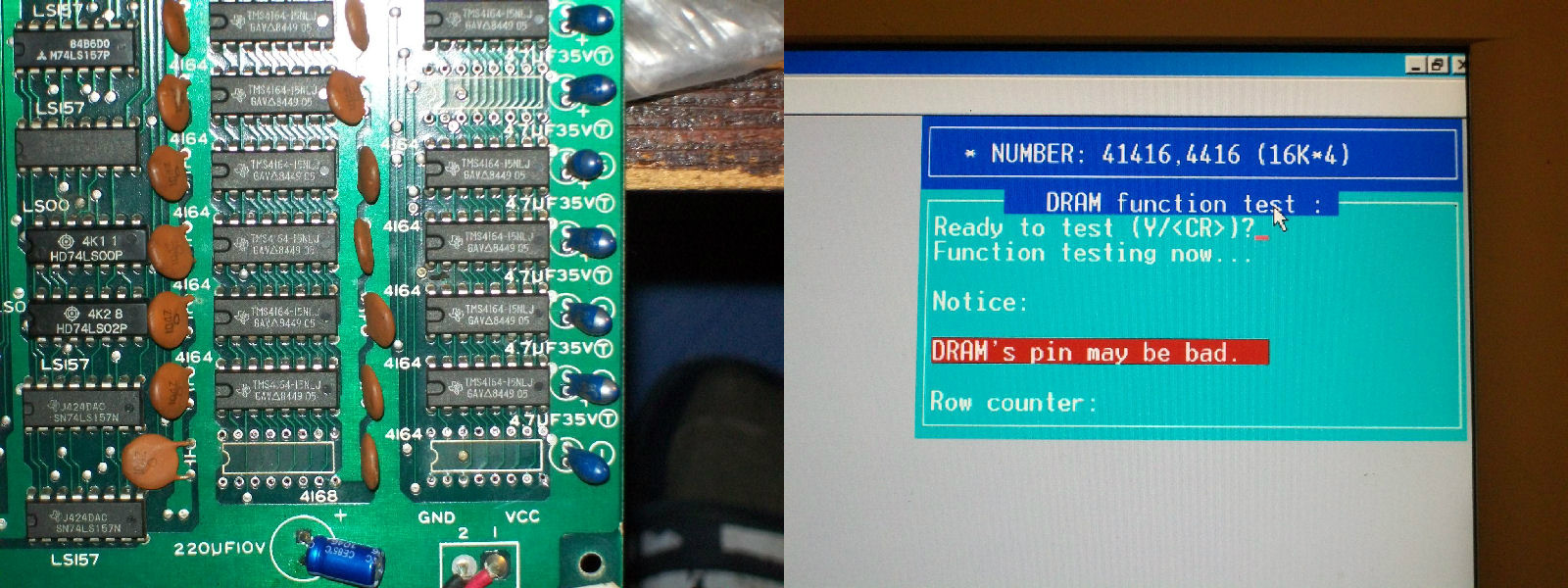
Character RAMs are eight 4416 DRAMs on the VIDEO board.Probing them I found that the three ones @2A, 2B and 4A had two DATA output lines stuck high while all address line were toggling properly.Once desoldered I tested them out-of-circuit and they failed miserably.Replacing them cleared the error on startup:
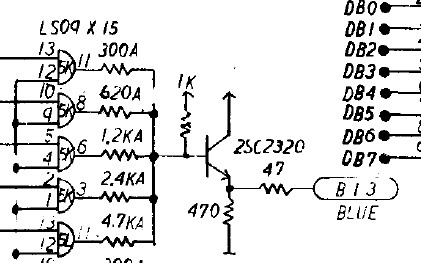
Finally I could pass the RAM/ROM TEST and enter into the game but clearly there was more work to do on.As you can see from pictures above screen was greeenish symptom that blue color was wrong.This color is digitally generated from this part of circuit:
st
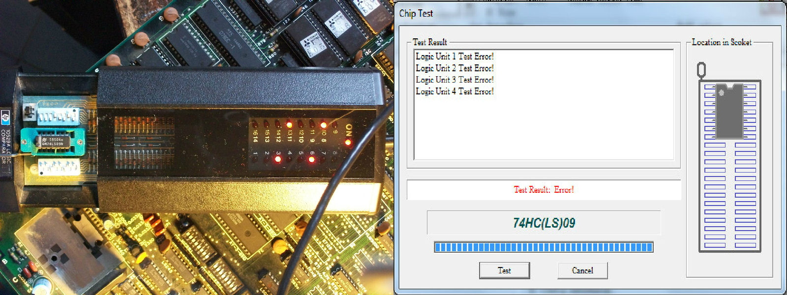
So I probed the 74LS09 @5K with my logic comparator which gave me troubles on all its outputs.It failed once tested out-of-circuit:
Colors were restored but sprites were completed missing replaced by vertical lines across the left half of the screen
Object RAMs are sixteen 4164 and probing them revelead that three of them (@2G-2H-6H) had stuck DATA output (PIN14).They were bad tested out-of-circuit:
But sadly this improved sprites a little as you can see:
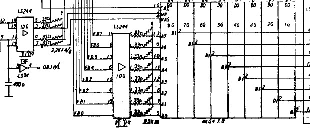
So I went again to probe object RAMs and found that all write enable lines were stuck high!There are two WR lines and each one is shared by eight DRAM.With the help of schematics I traced them back to a 74LS244 @13G which had some stuck outputs:
Piggybacking it restored sprites completely:
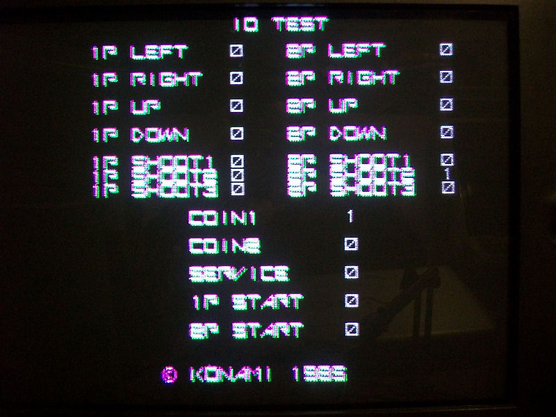
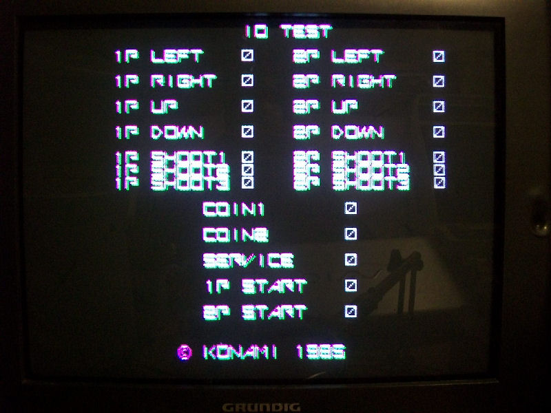
Graphics were perfect now game has no sound and two inputs were stuck as confirmed by I/O TEST:
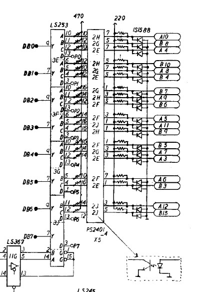
Looking at schematics I traced COIN1 back to a NEC PS2401 optocoupler @2H, piggy backing it cleared the fault so I replaced it.Piggybacking the one @2E for 2P SHOOT2 didn’t fix anything so fault was elsewhere .Between JAMMA edge inputs pin and PS2401 optocoupler there are some protection diodes (1S1588 type):
Probing the one @D1 connected to the 2P SHOOT2 revelead it was almost short-circuited as it showed a forward voltage drop of few mV compared to a good one:
Replacing it and inputs were all correctly working:
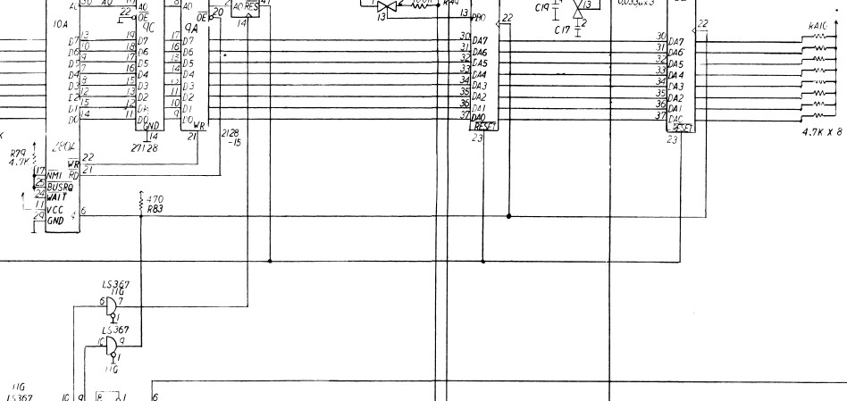
Lastly : the lack of sound.Probing the digital audio circuitry I noticed that Z80 and two AY-3-8910 sound generator were missing clock and this is generated by a 74LS367 @11G on CPU board:
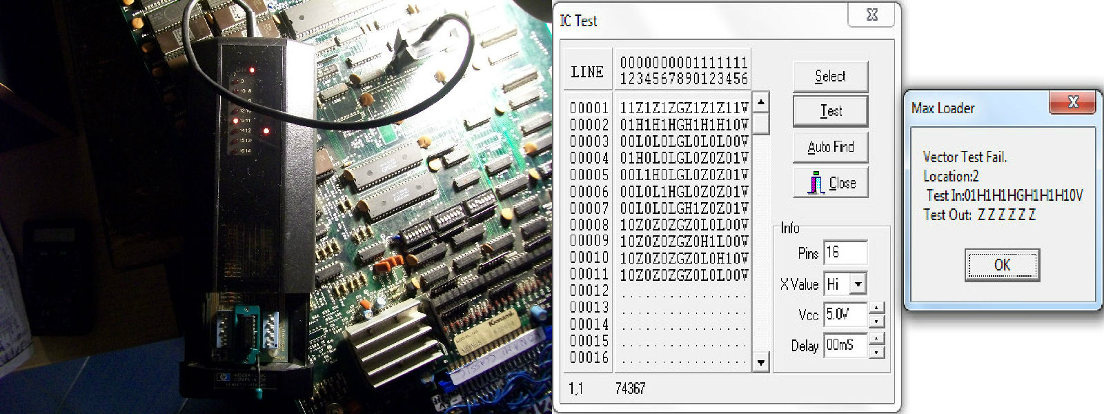
Comparing and testing it out-of-circuit confirmed it was bad:
But still had no sound at all.So I went to probe the analog section.Diverting the input of the LA4460 amp to an external amplifier I could hear sound so I replaced it.But some music tracks were clearly missing.From MAME source: sound is generated by a Konami SCC ‘005289″ ,a two channel sound generator indeed, each channel gets its waveform from a prom (4 bits wide).Address lines A0-A4 of the prom run to the 005289, giving 32 bytes per waveform. Address lines A5-A7 of the prom run to PA5-PA7 of the AY8910 control port A, giving 8 different waveforms.PA0-PA3 of the AY8910 control volume.
Probing the two 6301 BPROMs I found that address lines A5-A7 of the one @7A were inactive and, as described in MAME, they are addressed by the control port A of a AY-3-8910.This lead me to replace the AY-3-8910 chip @7E and this fully restored the sound.Board 100% fixed!
Just a quick note : all the TTL replaced were by Fujitsu manifacturer.
Do you have an oscilloscope and you never use it?Don’t sell it, now I will explain how to turn it into a simple but effective component tester.
The name “Octopus” maybe doesn’t say anything alone but if you google it along the words “curve tracer” you will obtain thousands of result.In few words an “Octopus” curve tracer is a small circuit that used in conjunction with a scope allows to display the voltage across a component under test on horizontal (X) axis versus the current through that component on the vertical (Y) axis.A scope set to X-Y mode is required (most of them have this feature).
There are lot of variants of “Octopus” circuit, personally I choose this one:
since it applies small voltage (less than 1VAC) and current (less than 1mA) allowing to test unpowered components also in circuit without risk of damaging them.
As you can from picture above circuit is made of very few common parts : there is a transformer 120VAC to 6.3VAC ( I’m in Europe so I used a 220VAC one), three resistors (the 560 Ohm and 100 Ohm ones forms a voltage divider to obtain 1VAC , then the 1KOhm one limits current to 1mA) and two probes.
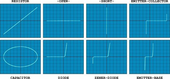
This circuit will produce a “signature” waveform on the oscilloscope to aid in the testing and analysis of shorts, opens, and leakage in just about any electronic component including resistors, capacitors, inductors, diodes,transistors and digital ICs too.Each component has a characteristic waveform (called “Lissajous” pattern), some examples:
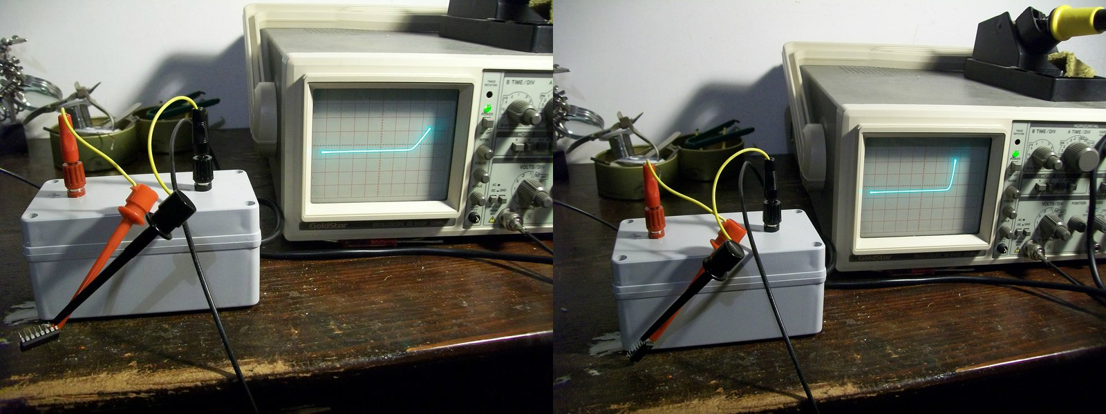
Now, you will wondering what this device has to do with arcade?Well, personally I find it very uself when I probe ICs out of circuit.For example, in my last repair I was unsure if a 74LS367 was good or not since I got discordant results from my testers.Probing it with the curve tracer and comparing its patterns with the ones of a good known IC removed all doubts:
On the right the pattern generated from a good IC (74LS367), on the left the one from the defective one.Specifically you can see how the junction (internally a TTL contains transistors) of an output (PIN9) is weakened compared to the good one (pattern doesn’t have the healthy ‘L’ shape of a good diode/base to collector junction)
Obviously this curve tracer can be used also to test components in-circuit (thanks to the low voltage/current applied) but in this case experience is needed as components can interact each other producing misleading results.The best option would be having a good board as reference.
If you want to read more about, I recommend you this document: