Caius

Irem M92 double repair log #1

 PCB Repair Logs  Comments Off on Irem M92 double repair log #1
Aug 112016
 

For the uninitiated the Irem M92 is an arcade platform introduced in 1991 by Irem.Technically speaking the system is  made from a top and bottom board, the top (main) board is common across the games, but the bottom (game) board can vary game to game.Each game has an encrypted sound cpu.Here are hardware specs:


  • CPU : V33 @ 9 MHz, V30 @ 7.159090 MHz
  • Sound Chip : YM2151 @ 3.579545 MHz, GA20 @ 3.579545 MHz
  • Other Chip : GA21, GA22

List of games on this platform:

  • Blade Master / Cross Blades! (1991)
  • Dream Soccer 94 (1994)
  • GunForce (1991)
  • Gunforce 2 / Geostorm (1994)
  • Hook (1992)
  • In the Hunt / Kaitei Daisensou (1993)
  • Lethal Thunder / Thunder Blaster (1991)
  • Major Title 2 / The Irem Skins Game (1992)
  • Mystic Riders / Gun Hohki (1992)
  • Ninja Baseball Batman / Yakyuu Kakutou League-Man (1993)
  • Perfect Soldiers / Superior Soldiers (1993)
  • R-Type Leo (1992)
  • Undercover Cops (1992)

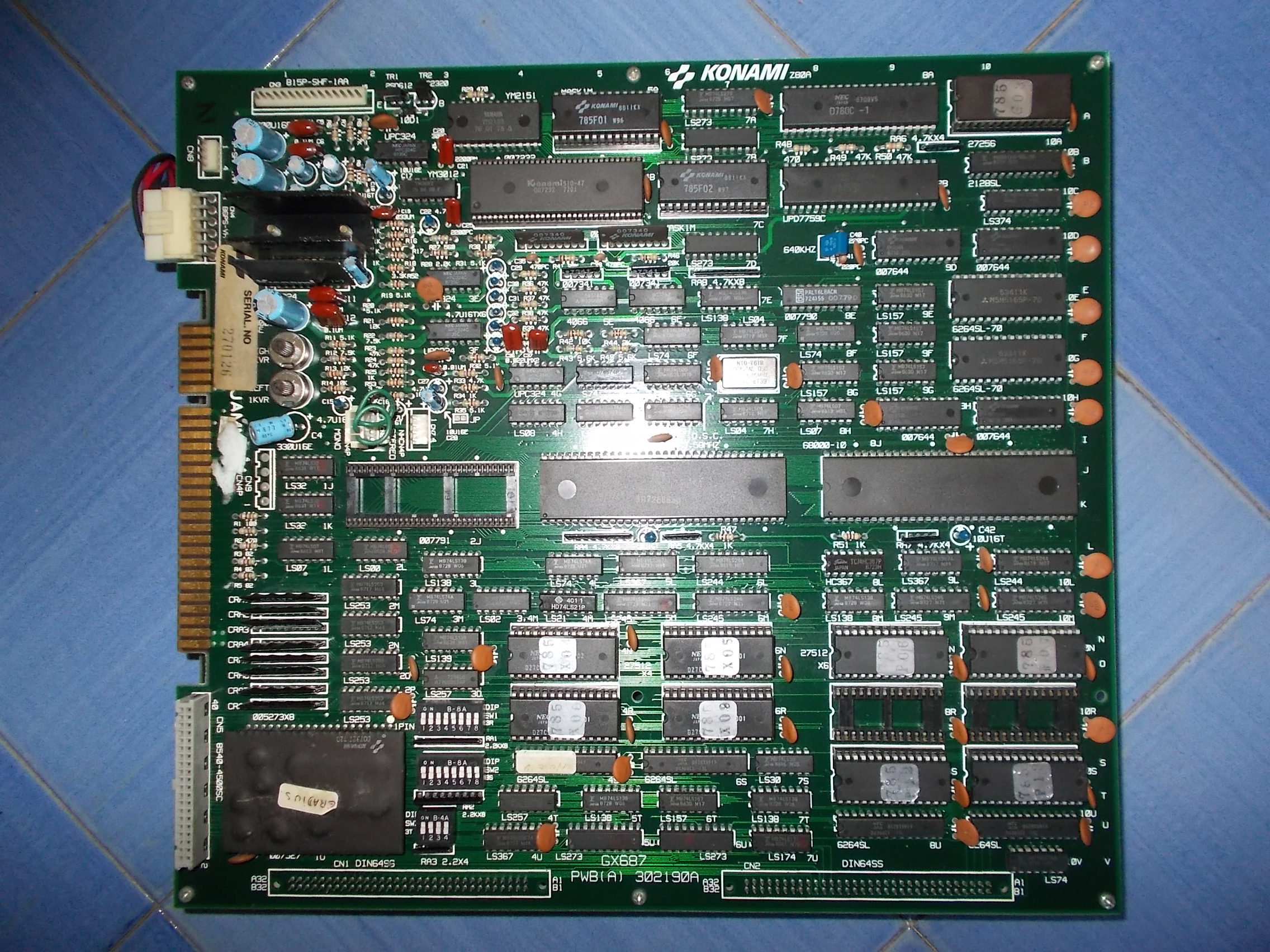
With these premises I begun my troubleshooting on an Undercover Cops and GunForce PCBs.

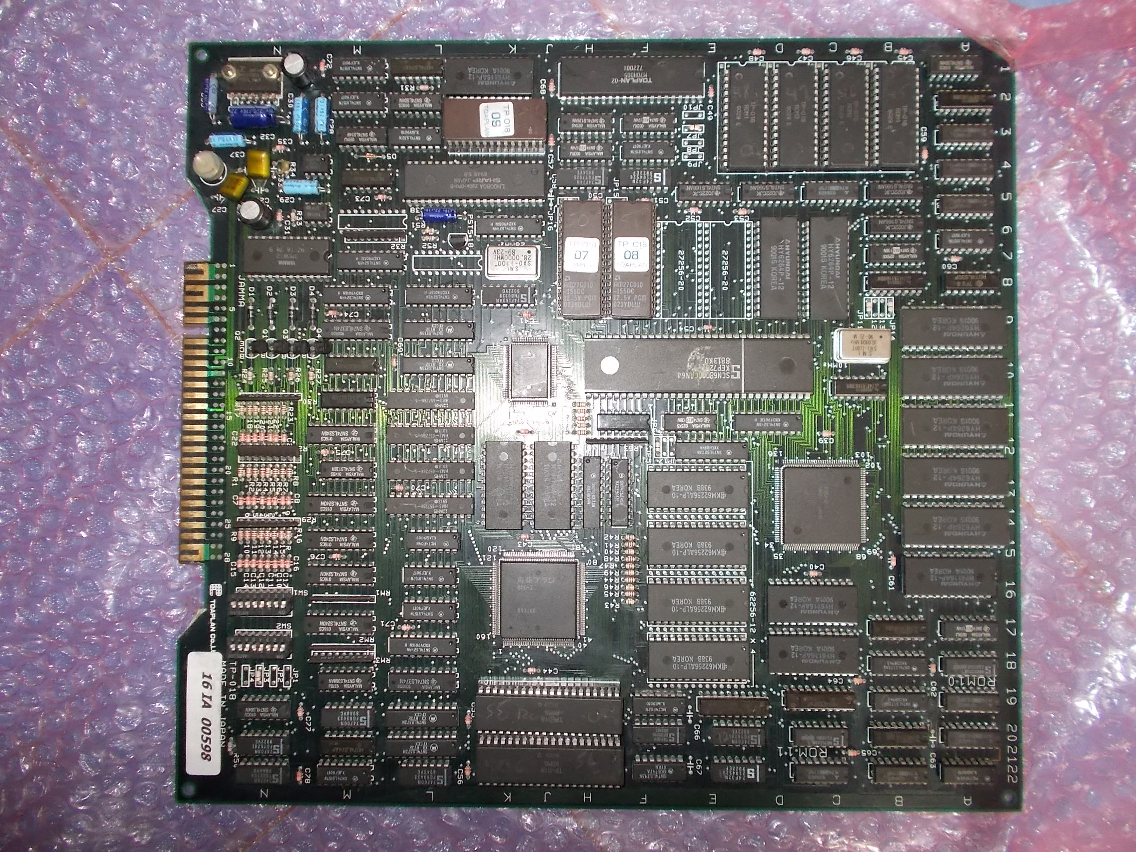
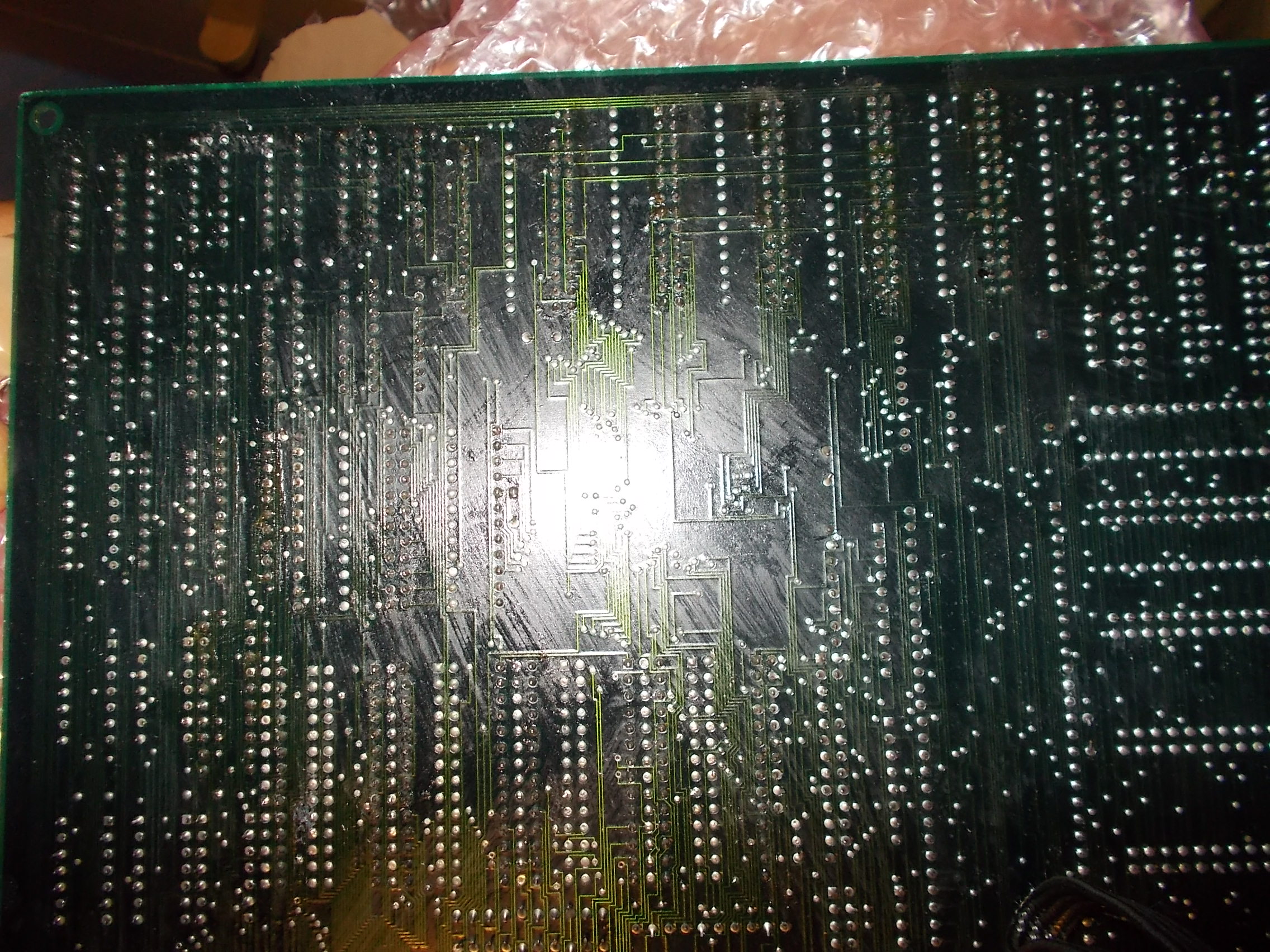
I bought the first as faulty:

100_8497

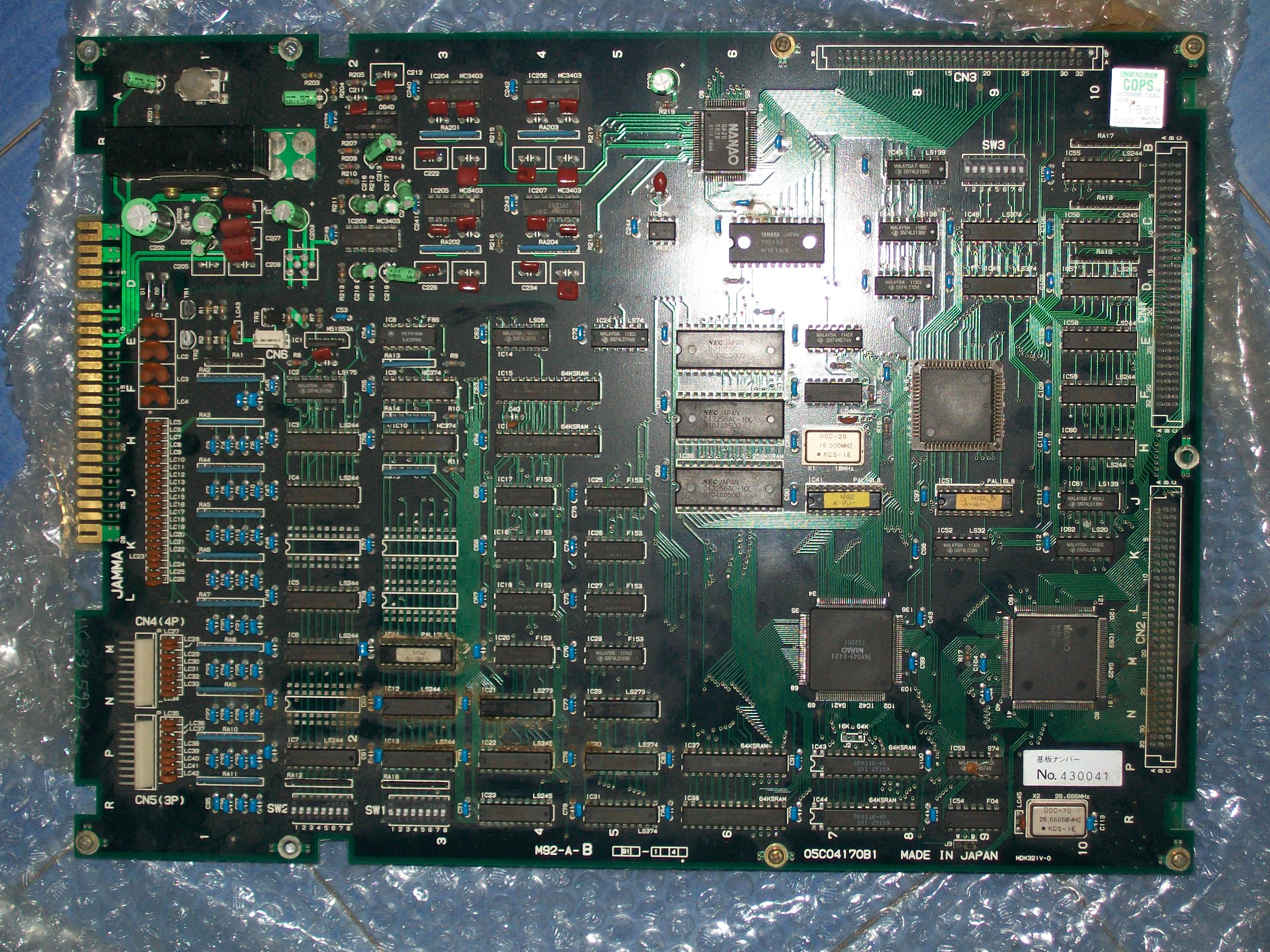
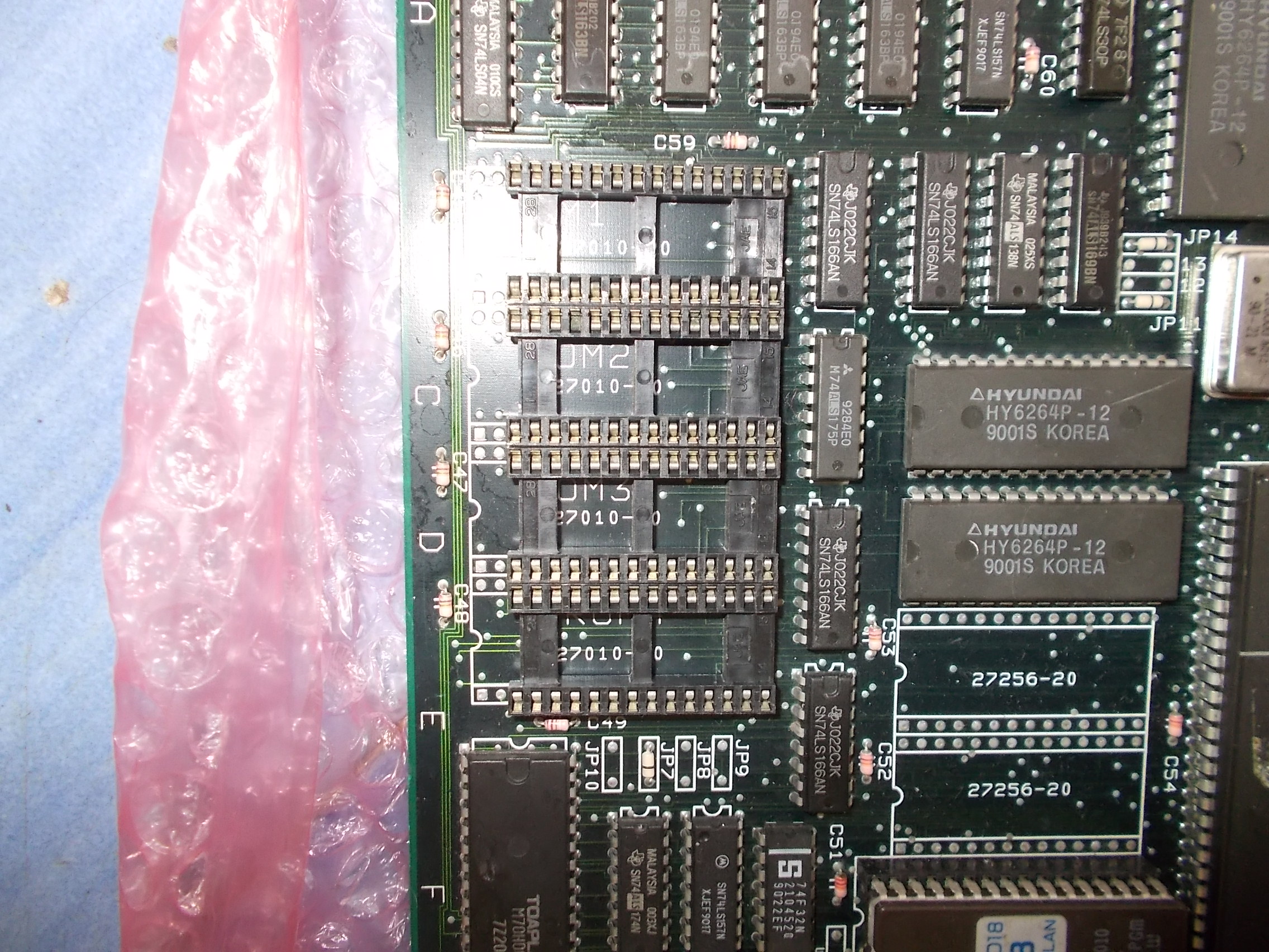
Seller warned me about severe corrosion in some area of PCB, this was confimed once received the board, it seems like the board has been stored in a very humid place :

100_8498

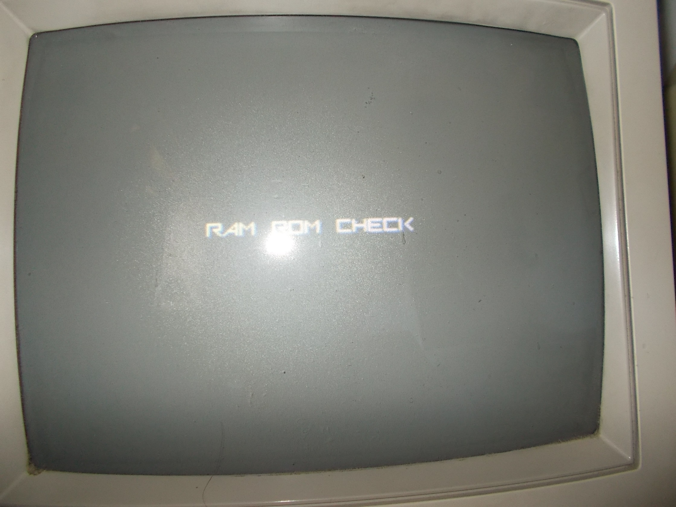
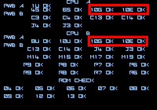
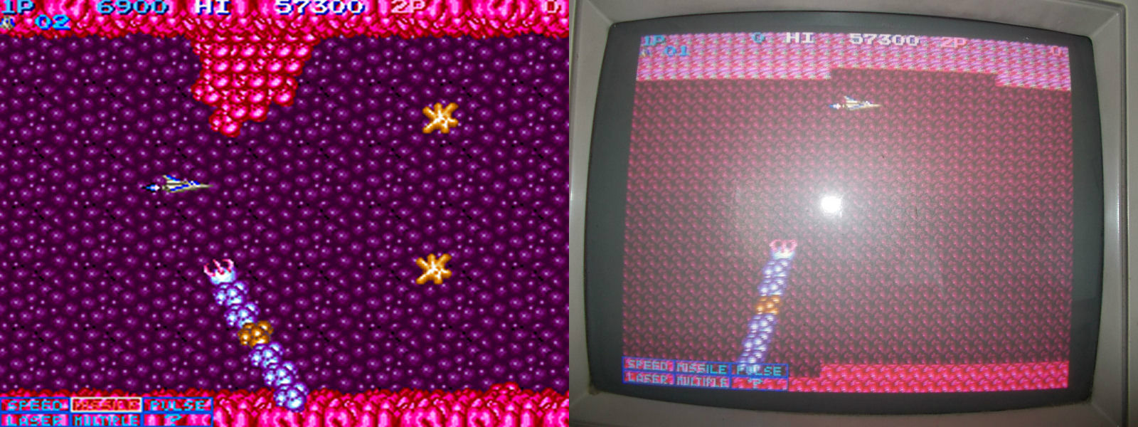
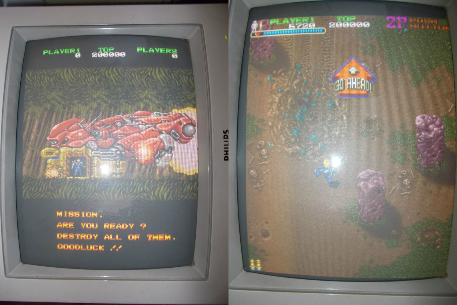
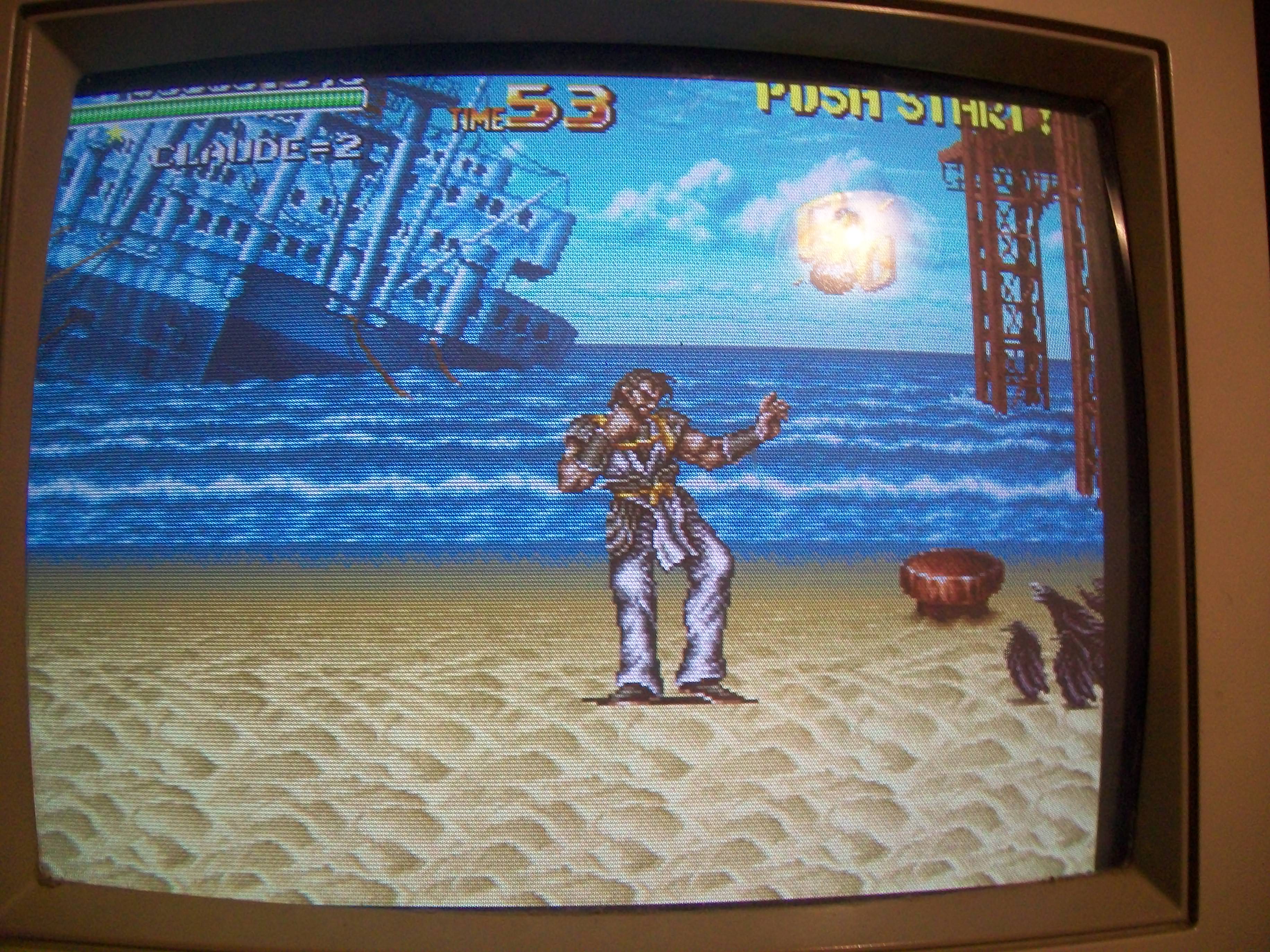
Anyway, once powered it up I got this:

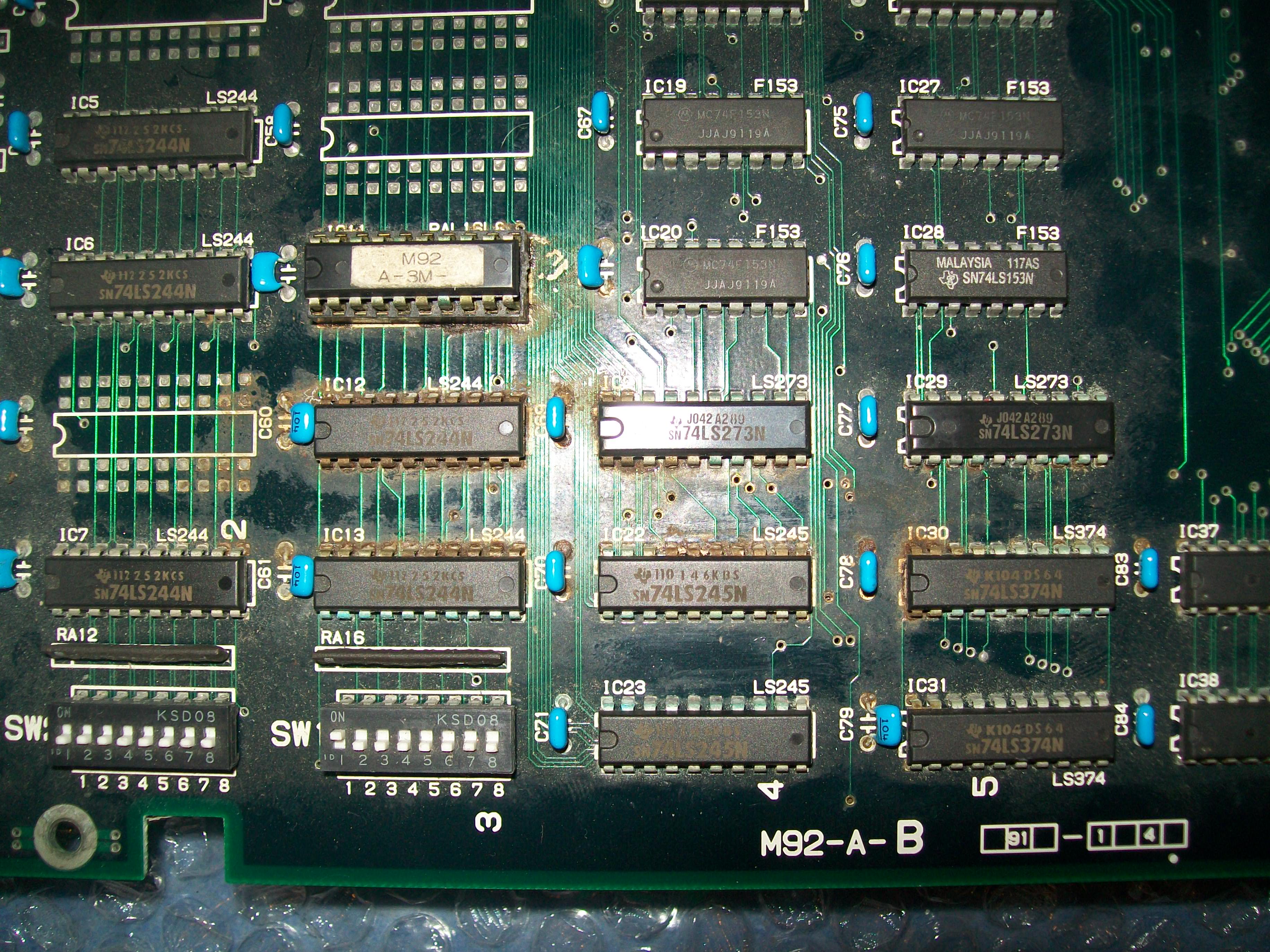
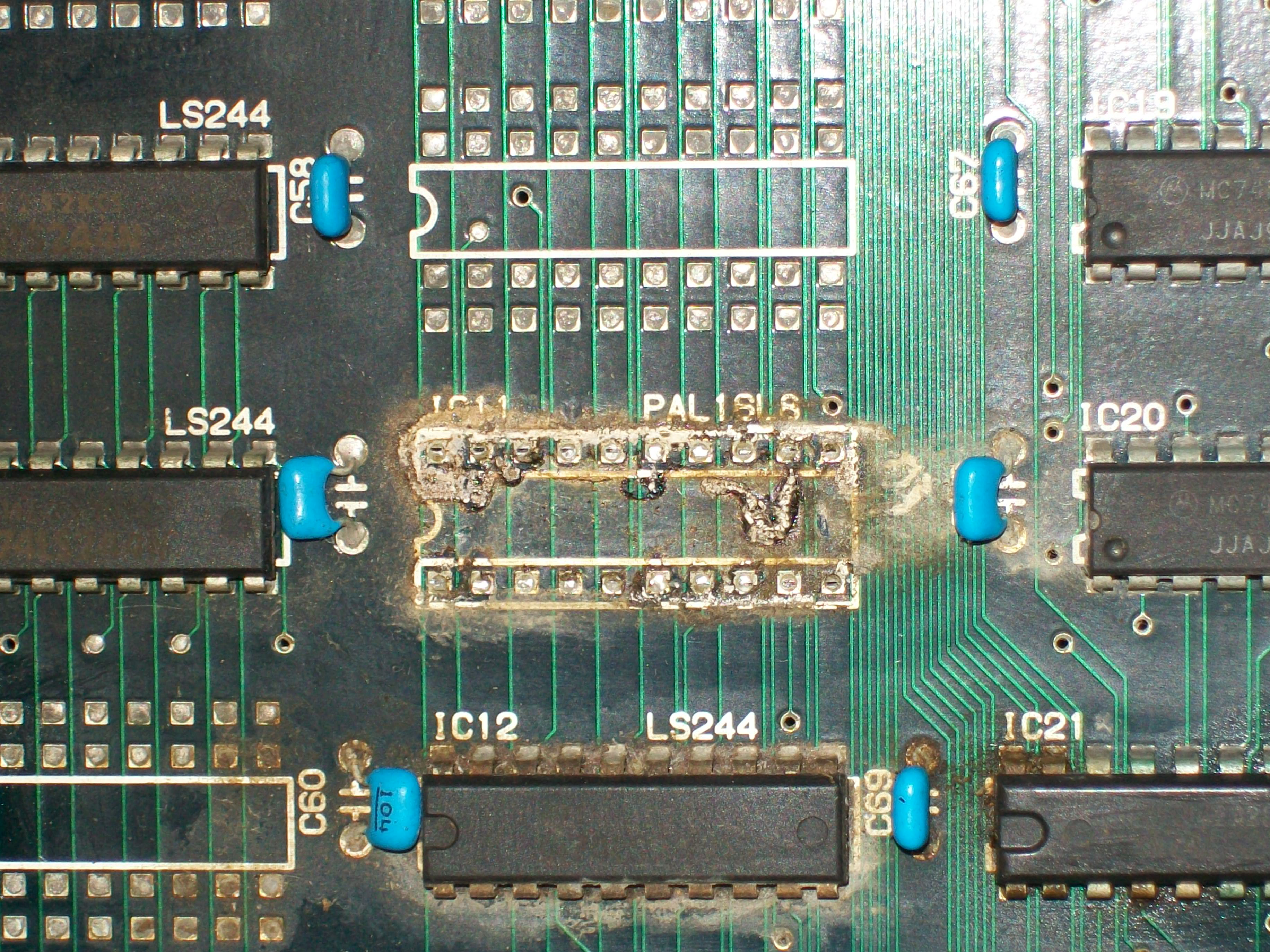
Game actually played blind.I noticed that if I pressed the PAL marked “M92-A3-M” @IC11  graphics were restored in a bad way though:

100_8503

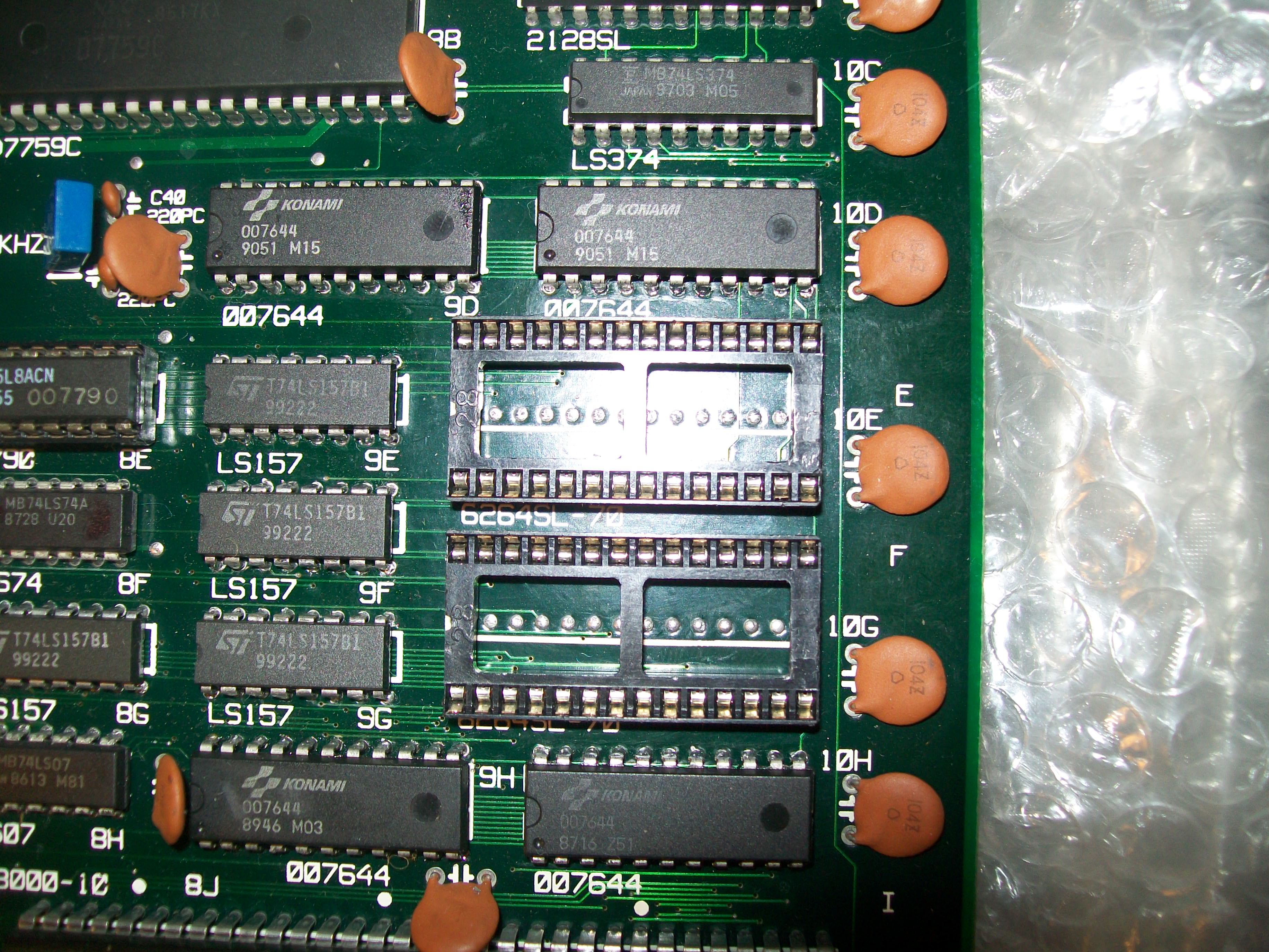
This was not a case since this PAL was located in the corroded area so I decided to remove the socket.Underneath I found this scenario:

100_8501

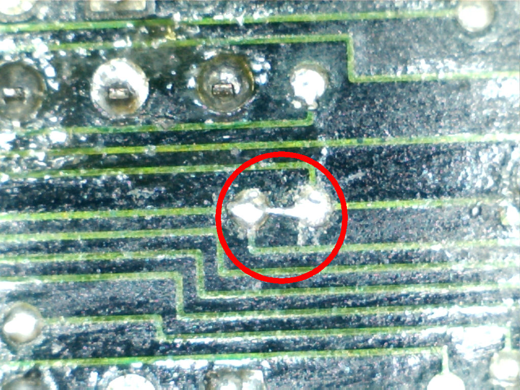
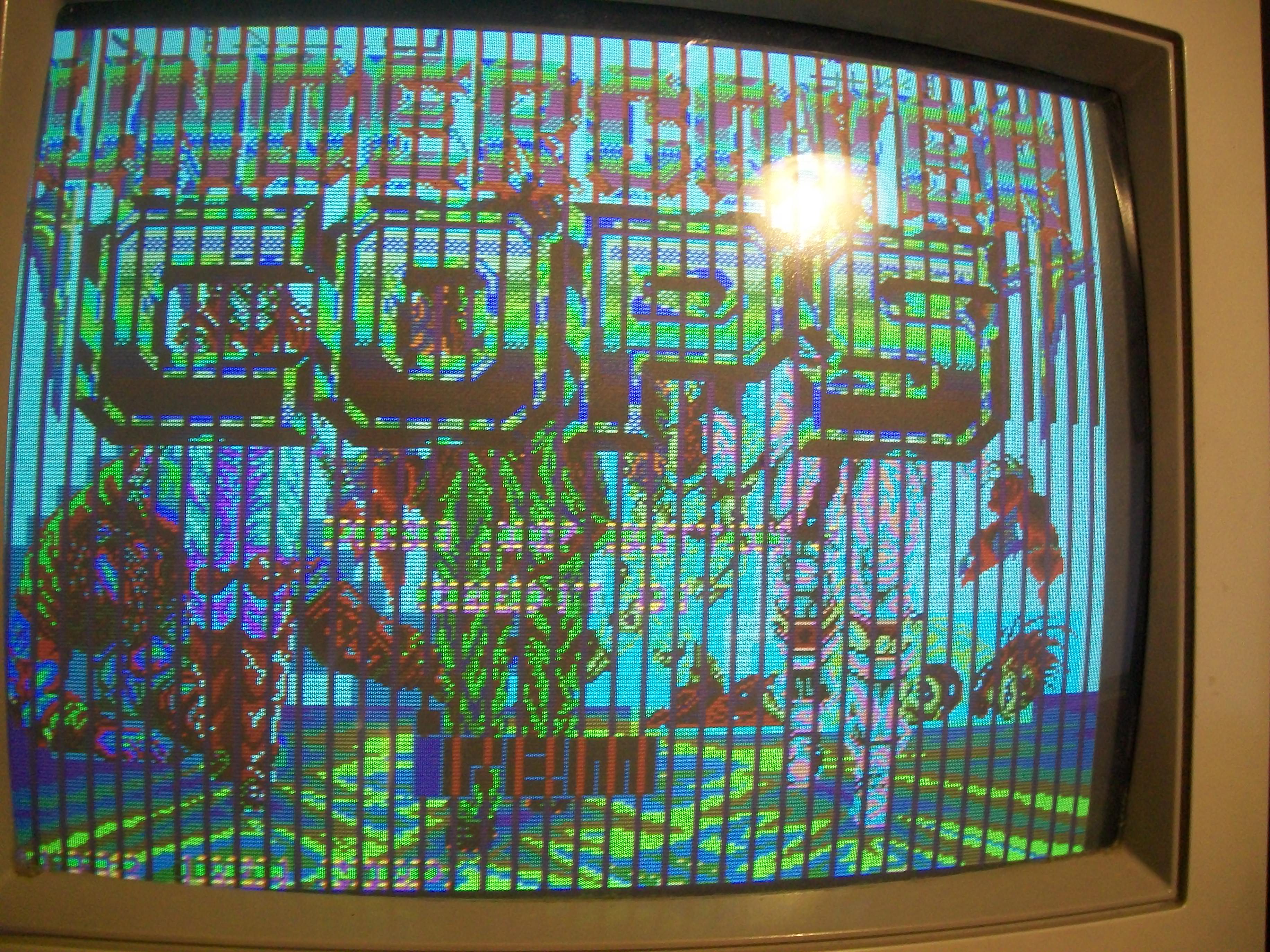
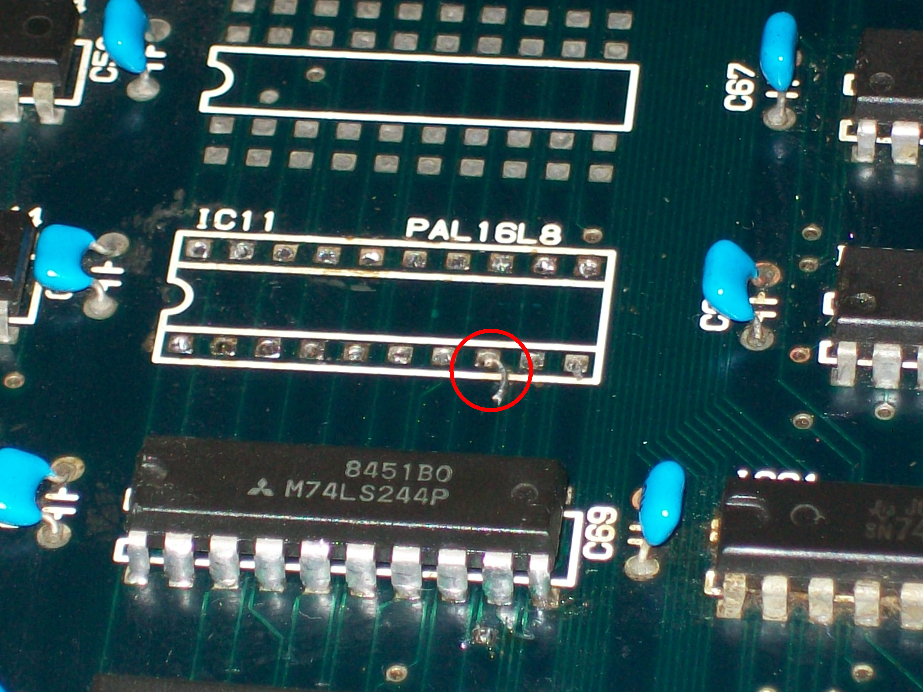
After cleaning from corrosion, I checked all the connections and found a missing contact bewteen pad of pin 8 (an input of the PAL) and its trace which I promptly patched with some kynar wire:

100_8509

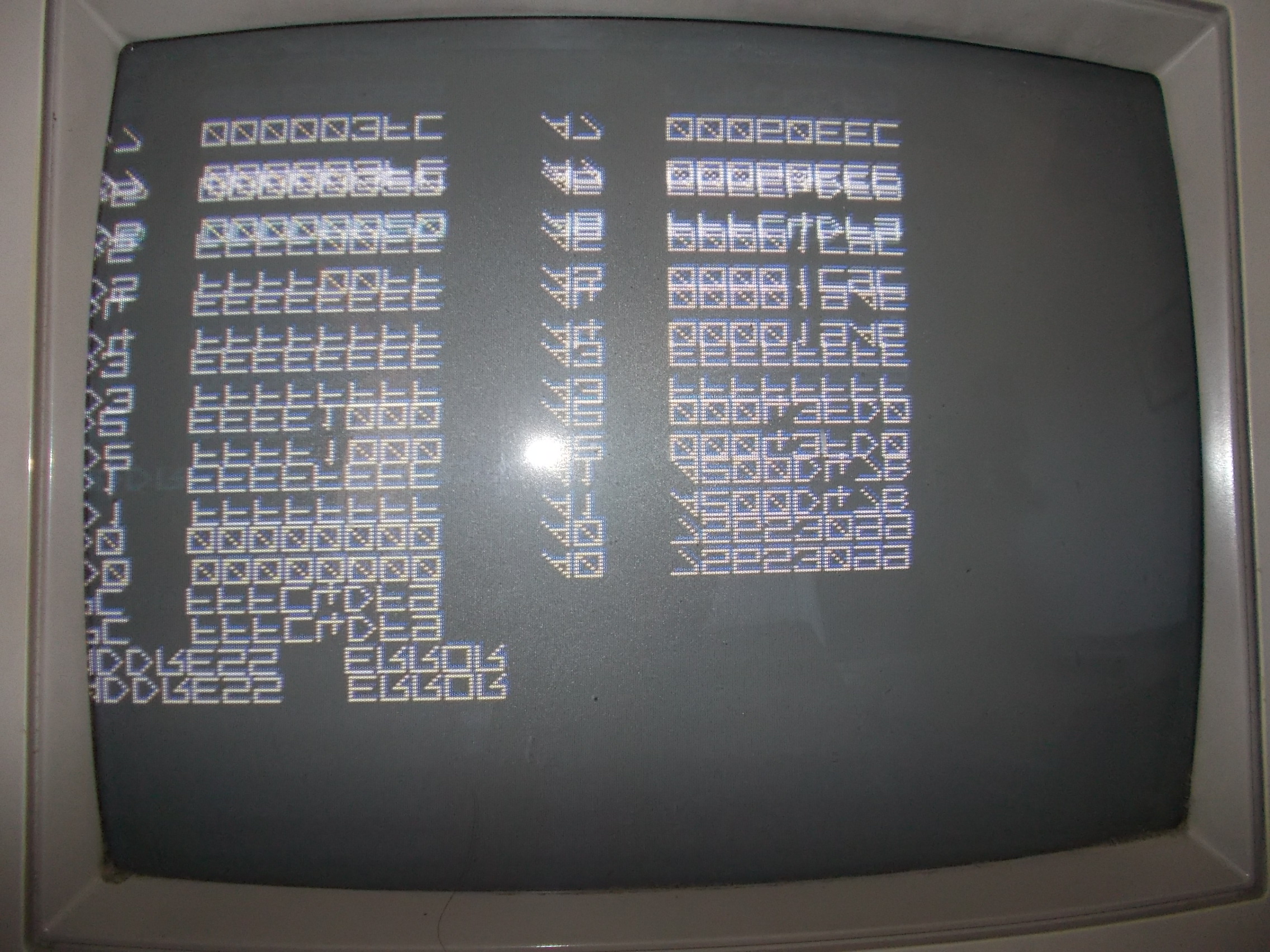
With this fix graphics were almost good but there were jailbars all over the screen:

100_8507

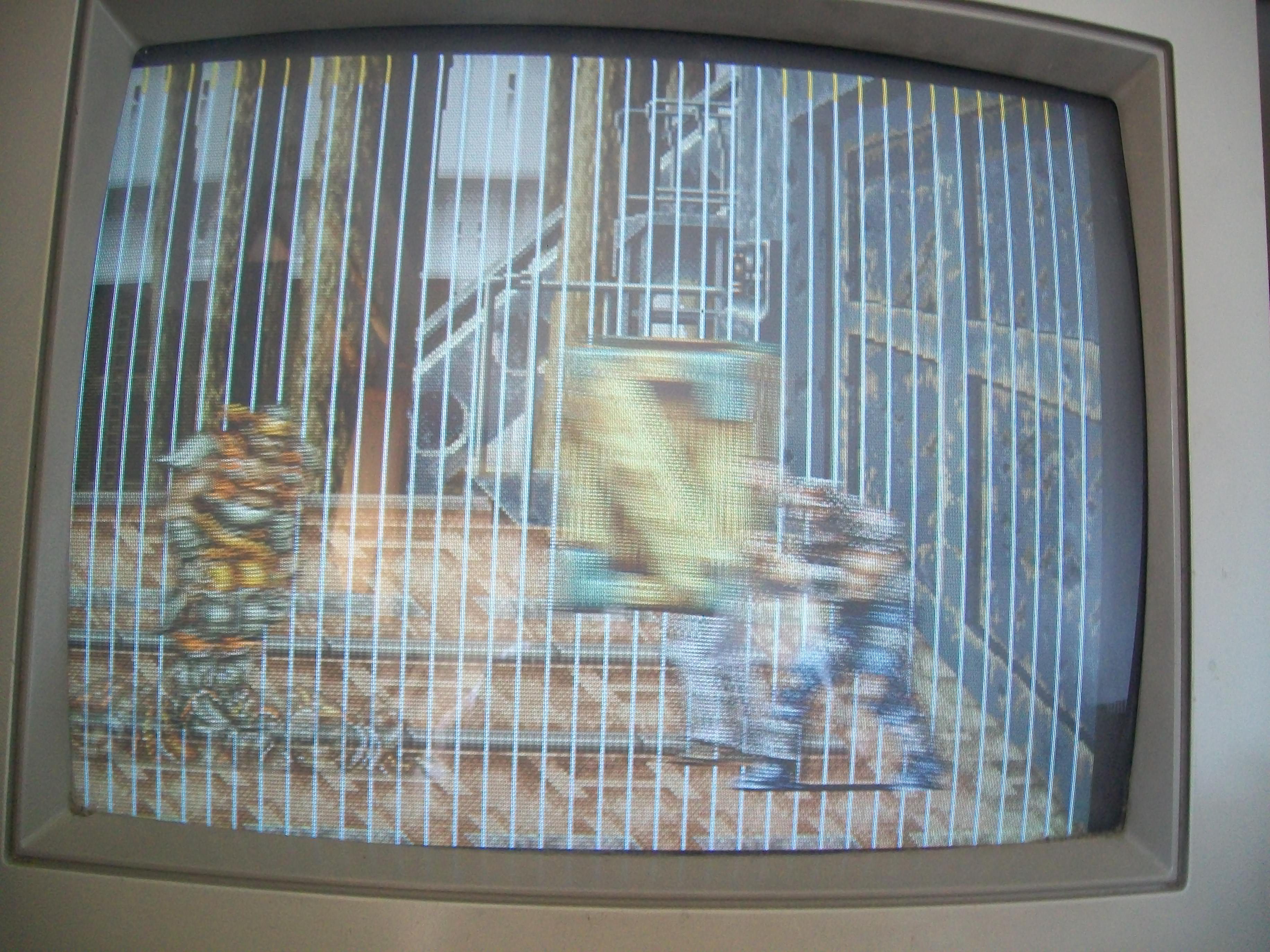
Again, pressing a specific area of the PCB restored graphics temporarily so I started to look around until I was able to locate the cause of that issue:

100_8515

lifted_pins

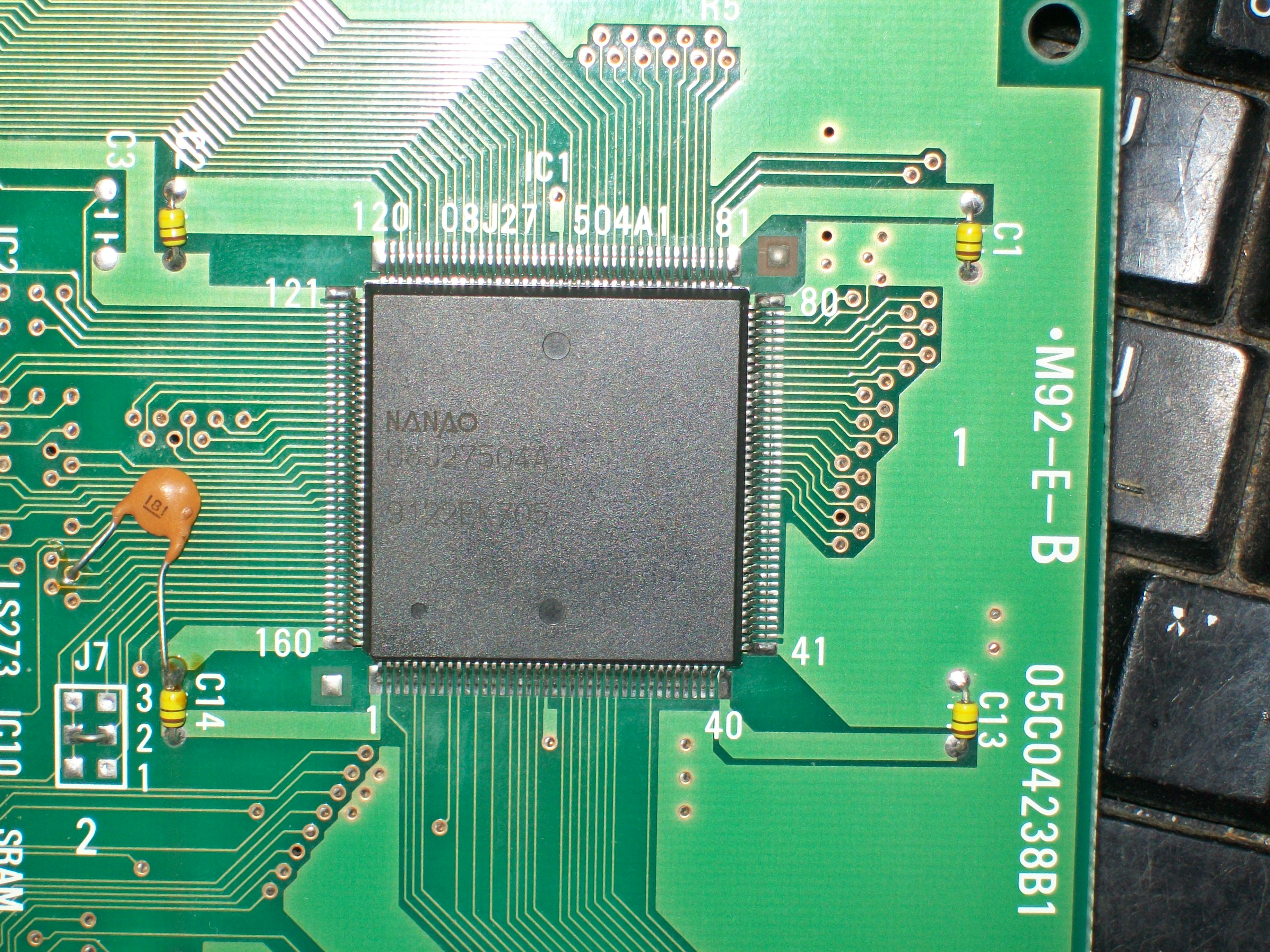
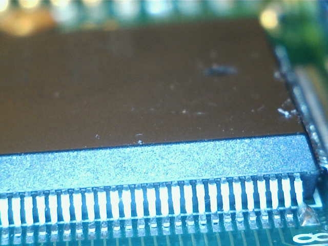
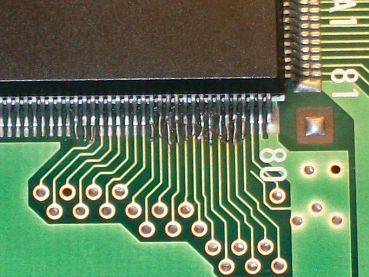
Several pins of a custom ASIC on the video board were lifted.Since the pads were corroded too,a reflow was not enough to ensure a good soldering so I decided to reinforce it using some pieces of AWG3o wire :

100_8520

This fixed this first M92 board completely:

100_8505

So I moved on the GunForce PCB:

100_8522

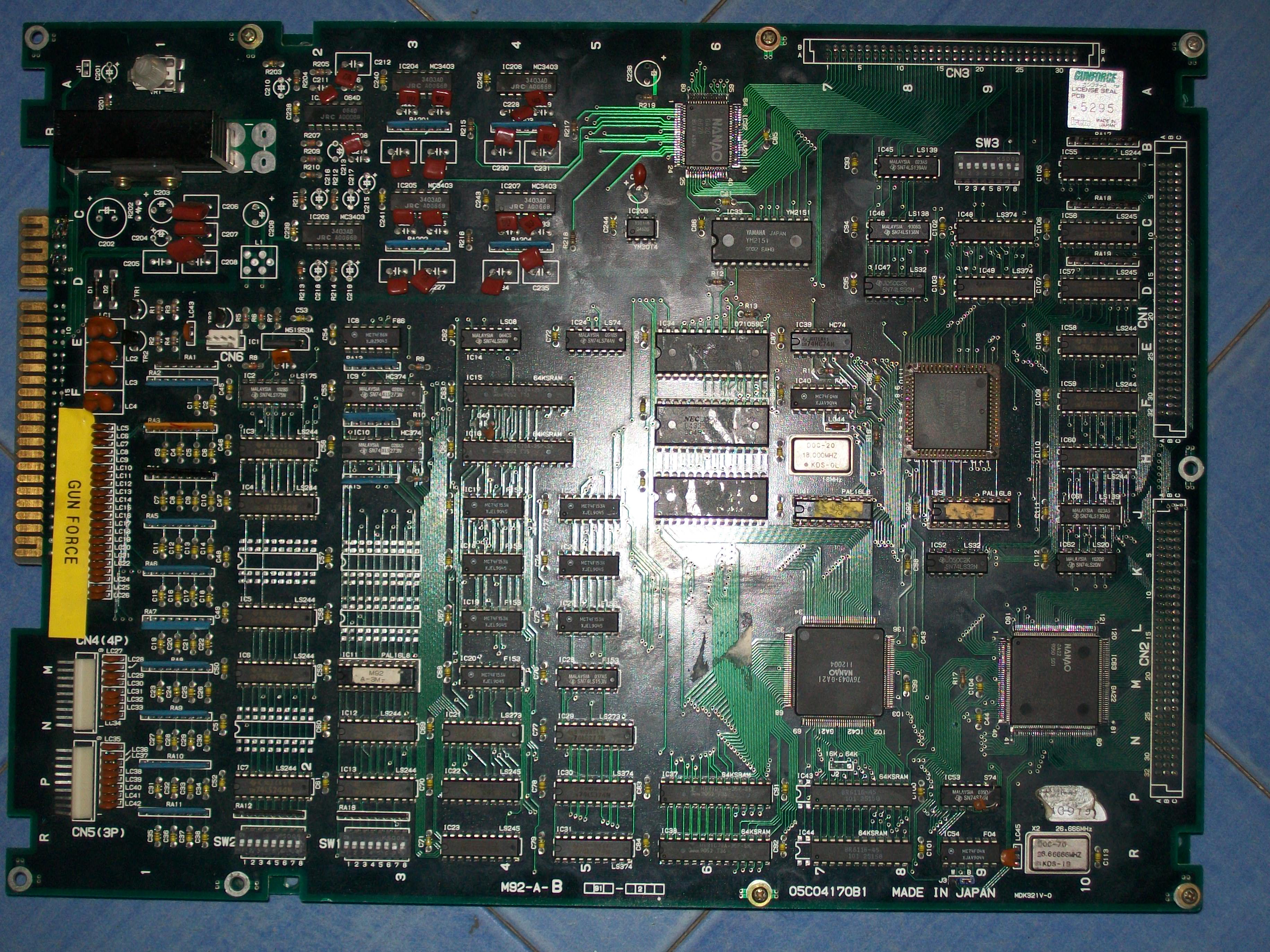
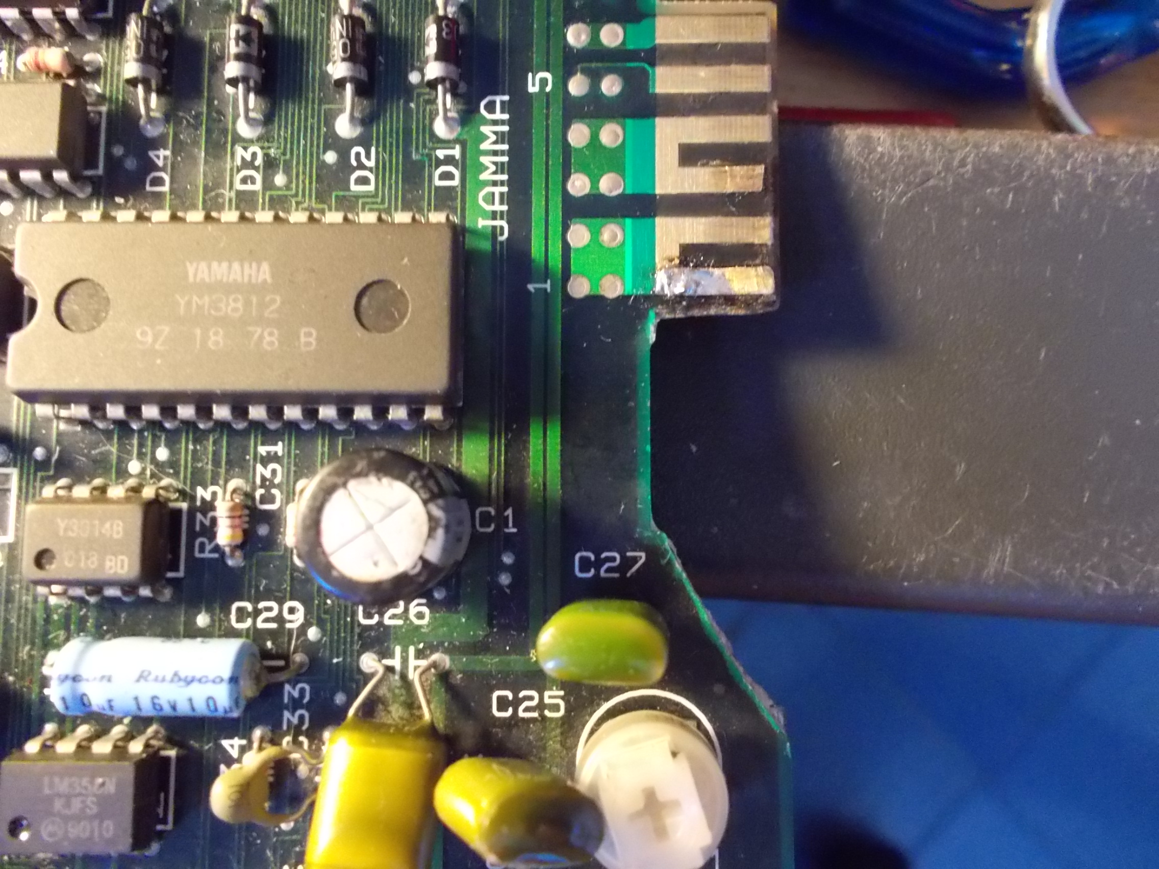
First thing I noticed after my visual inspection was the lack on many electrolytic capacitors in the audio circuit:

missing_capacitors

Board booted up but video as disturbed and a rustling sound was present on backgorund :

Usually this issues are caused by increased ESR of elecrolytic capacitors which inject disturbs on video circuit as well.The previous repairer thought about this and therefore removed all the electrolytic capacitors but this didn’t cure the problem.But He forgot to check the main amplifier:

100_8527

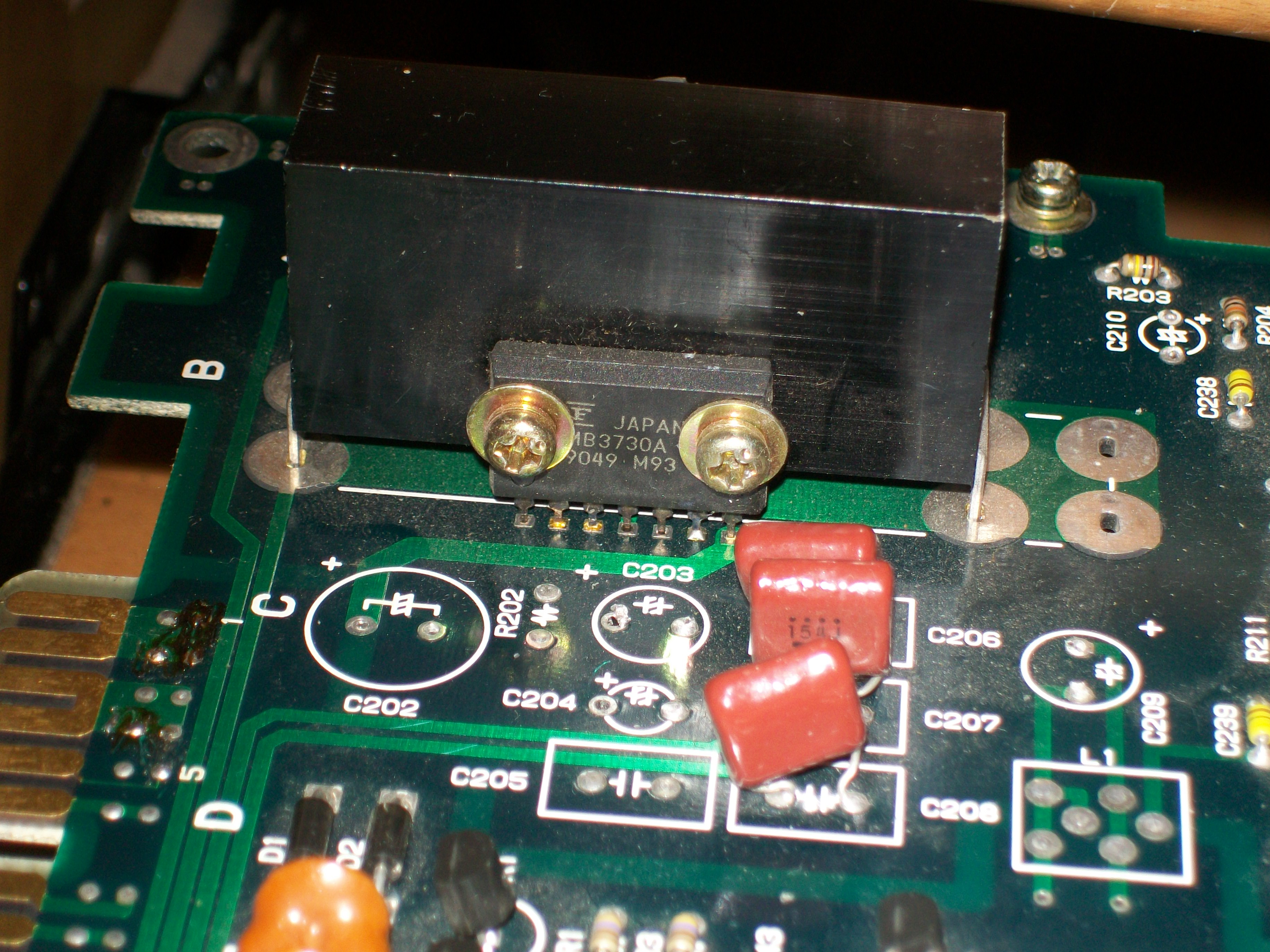
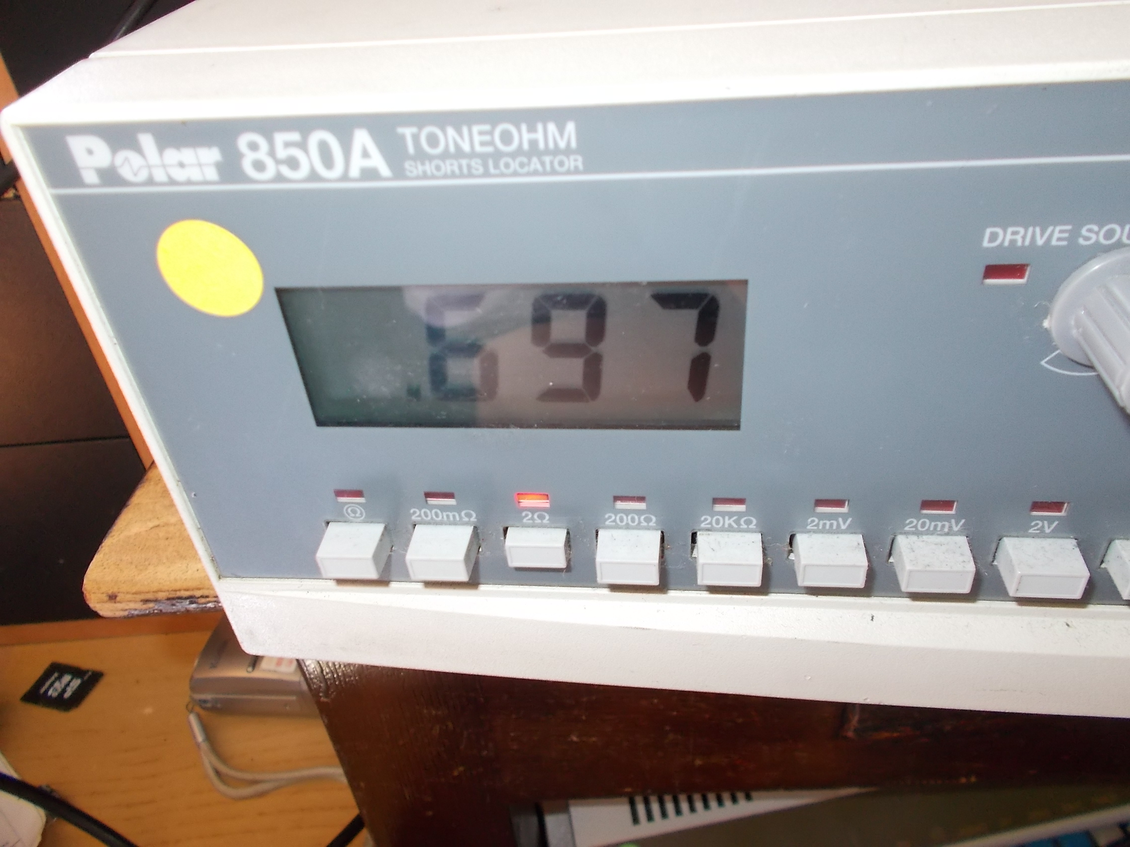
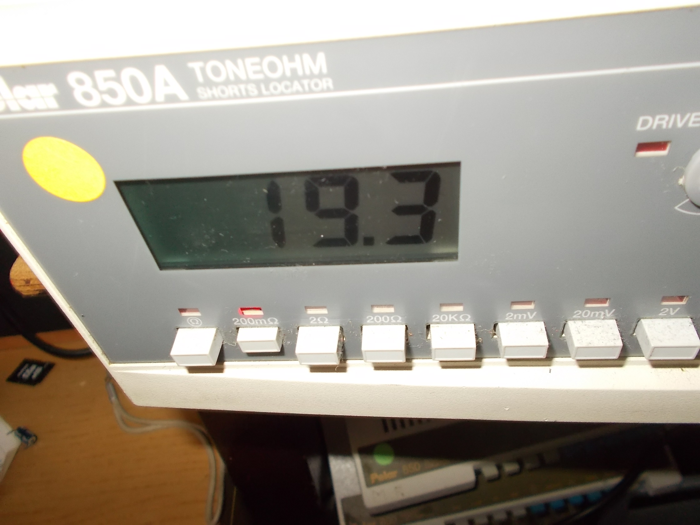
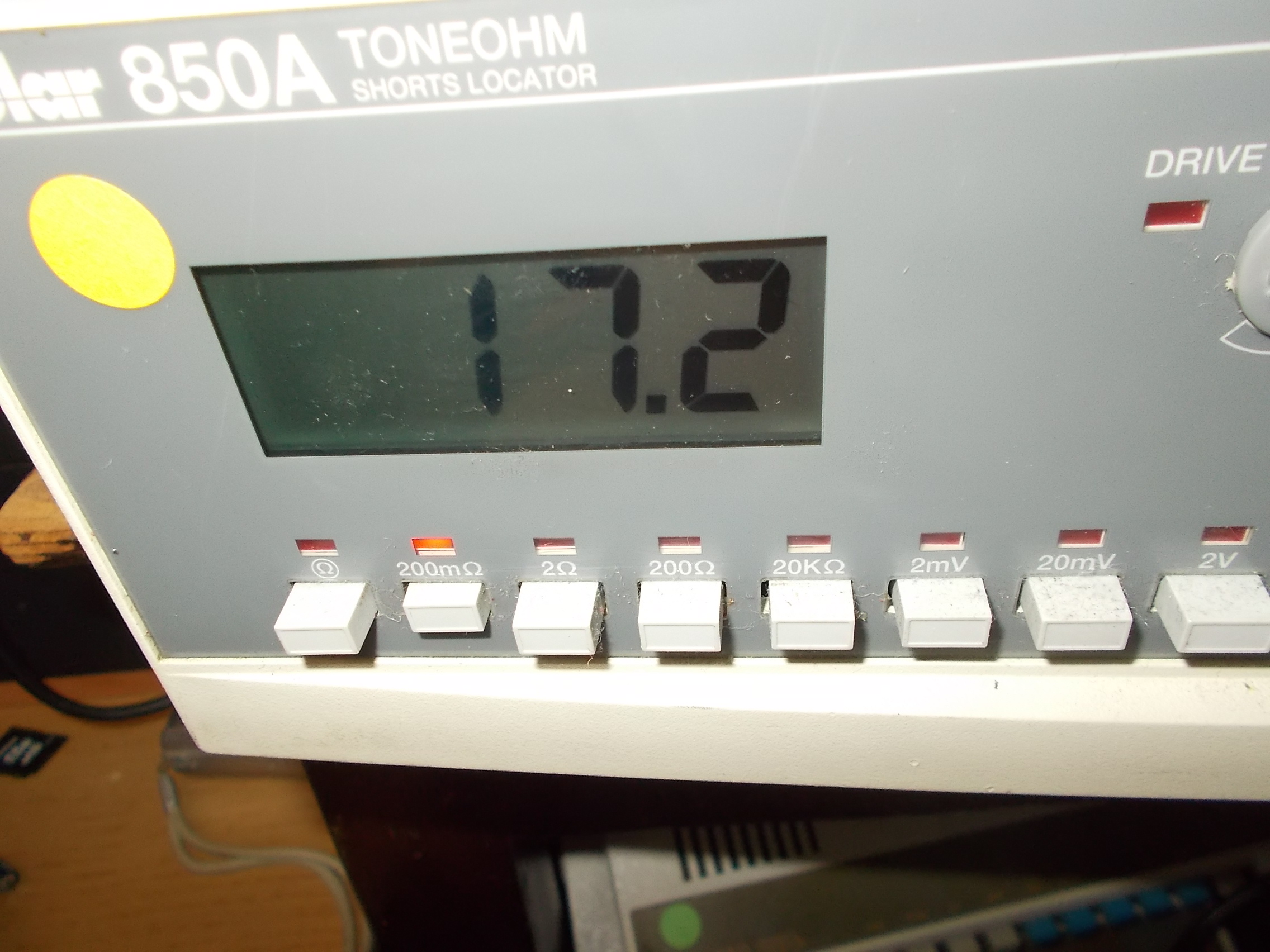
Probing in AC the +12V line with my scope confirmed that ripple was present:

100_8525

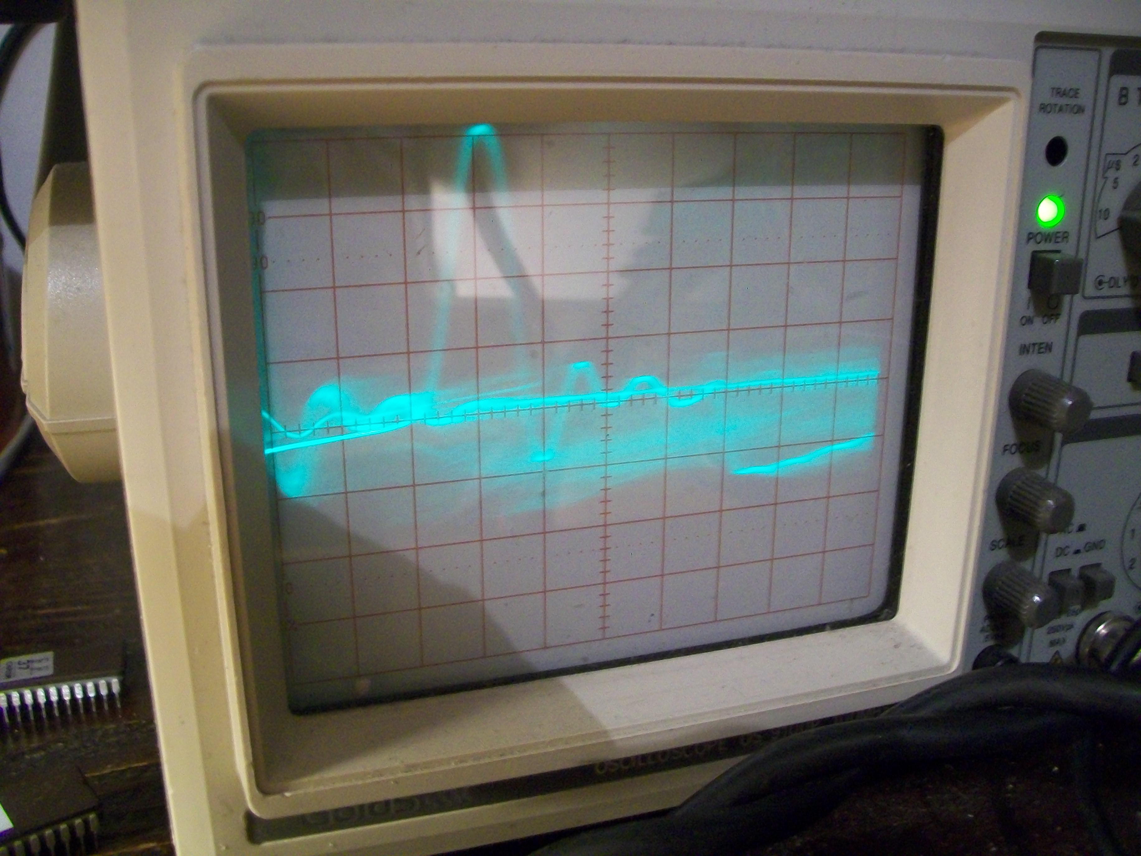
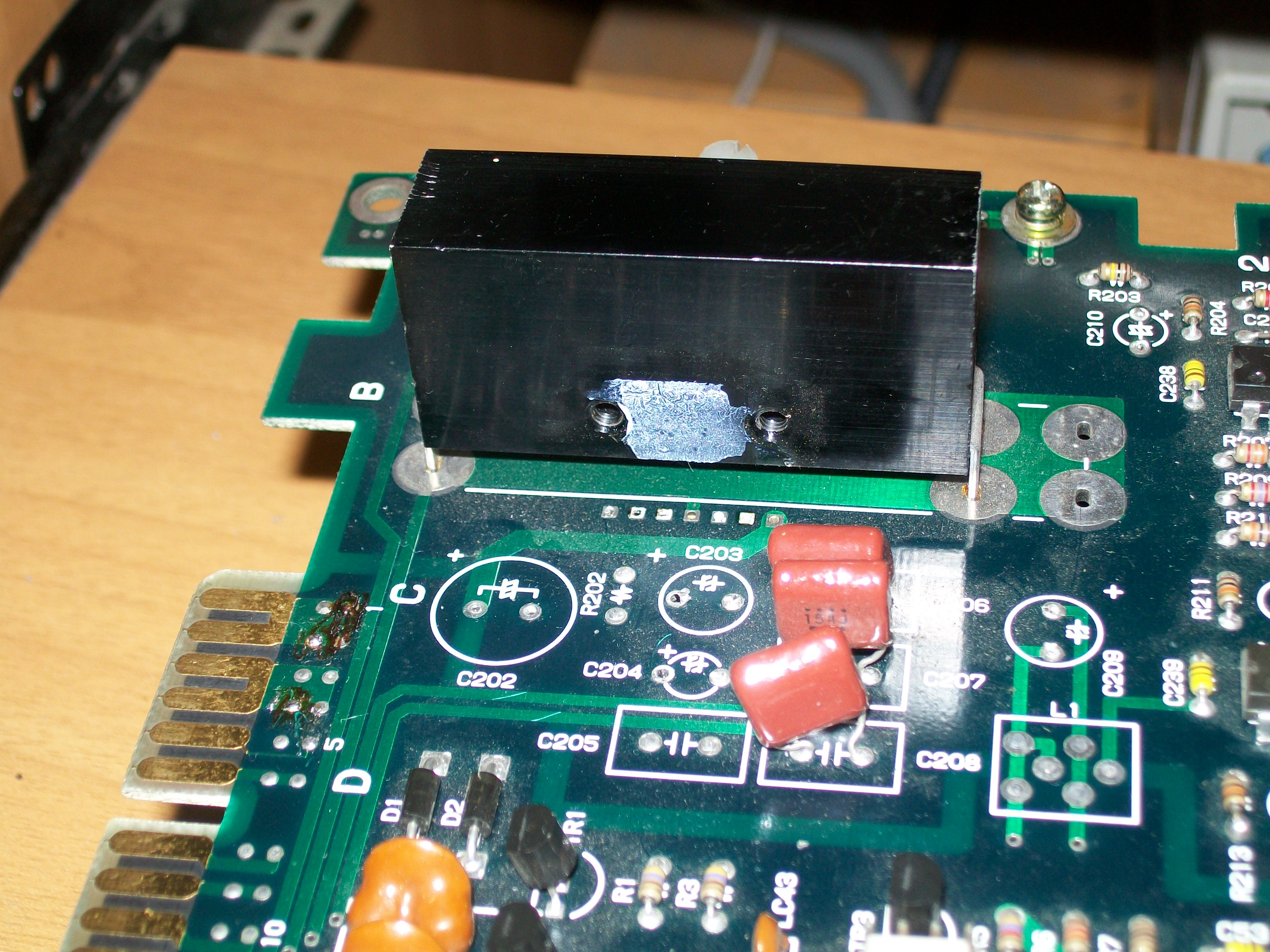
If I excluded the +12V from my supergun the video became normal and no more rustling sound.So, since on PCB there was no other component connected to this supply line, the amplifier was most likely the culprit.I removed it :

100_8539

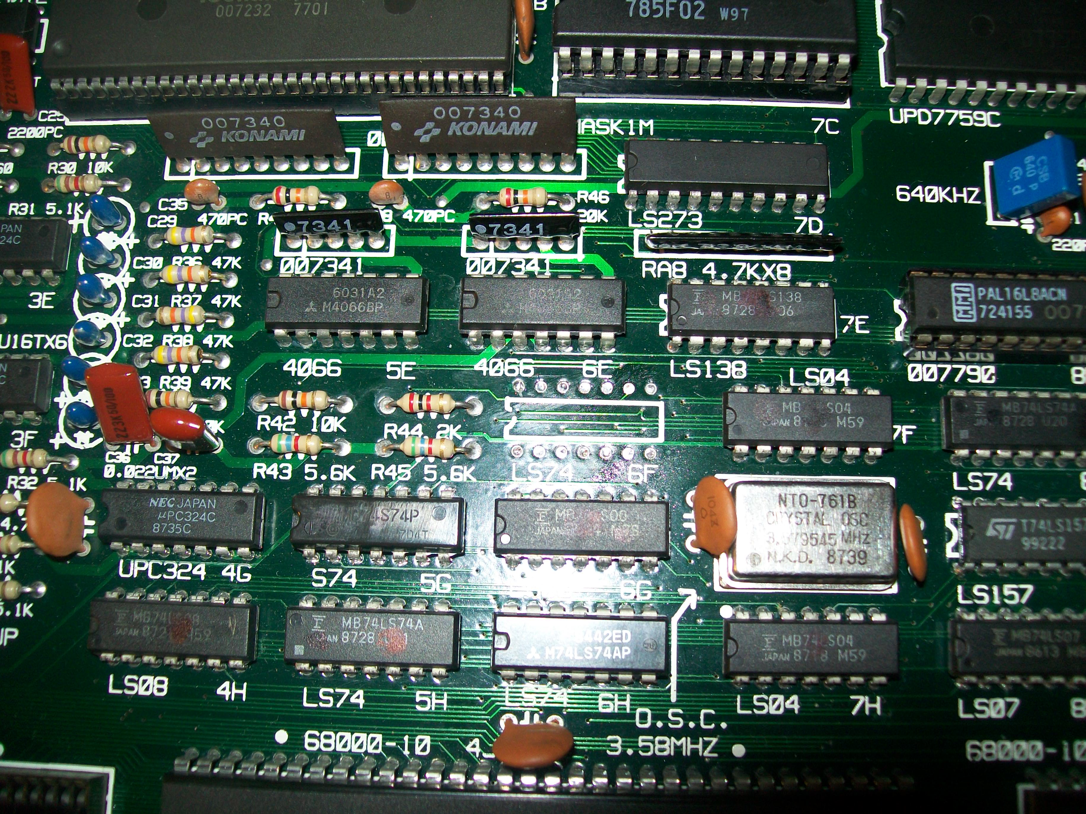
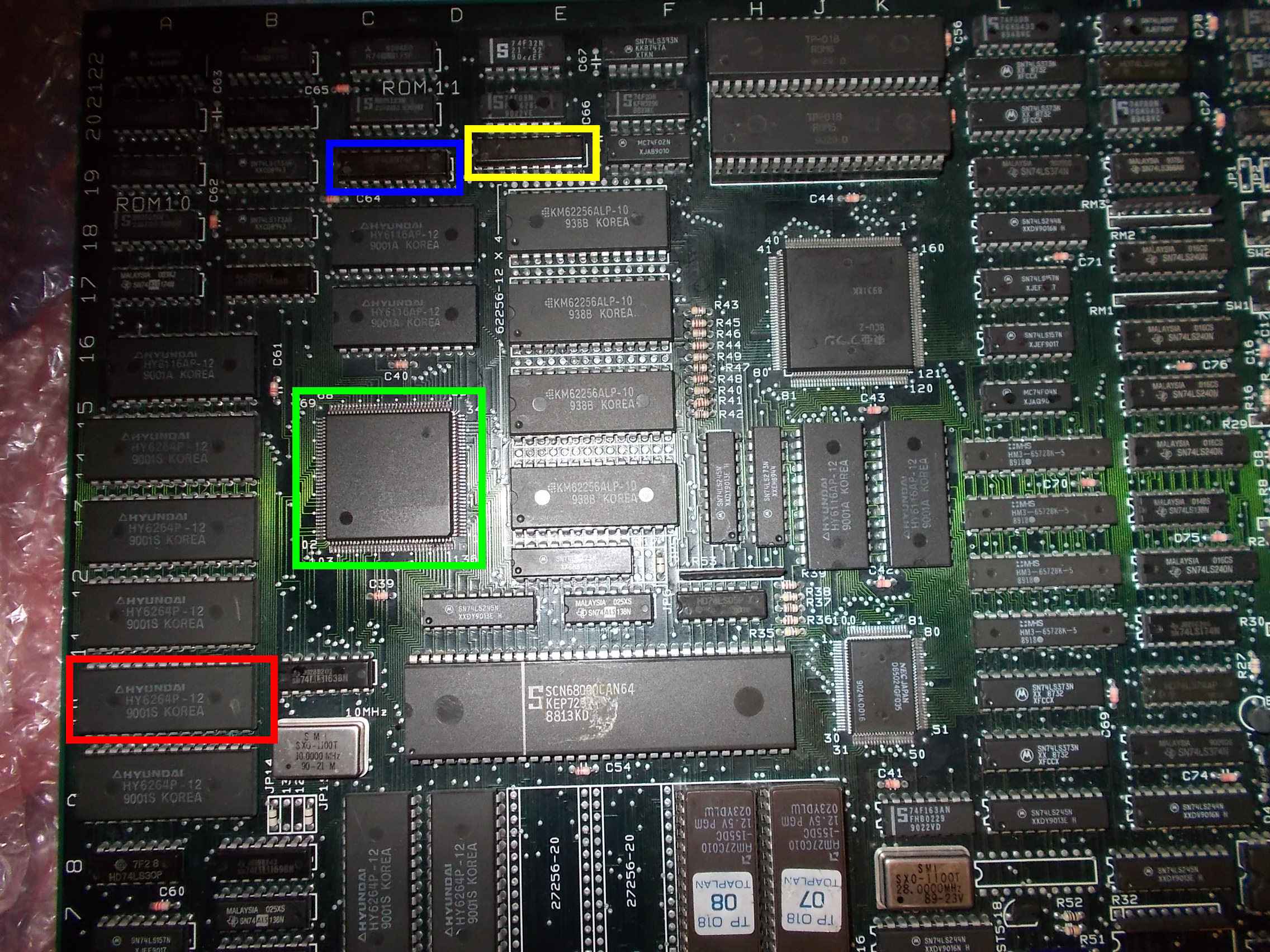
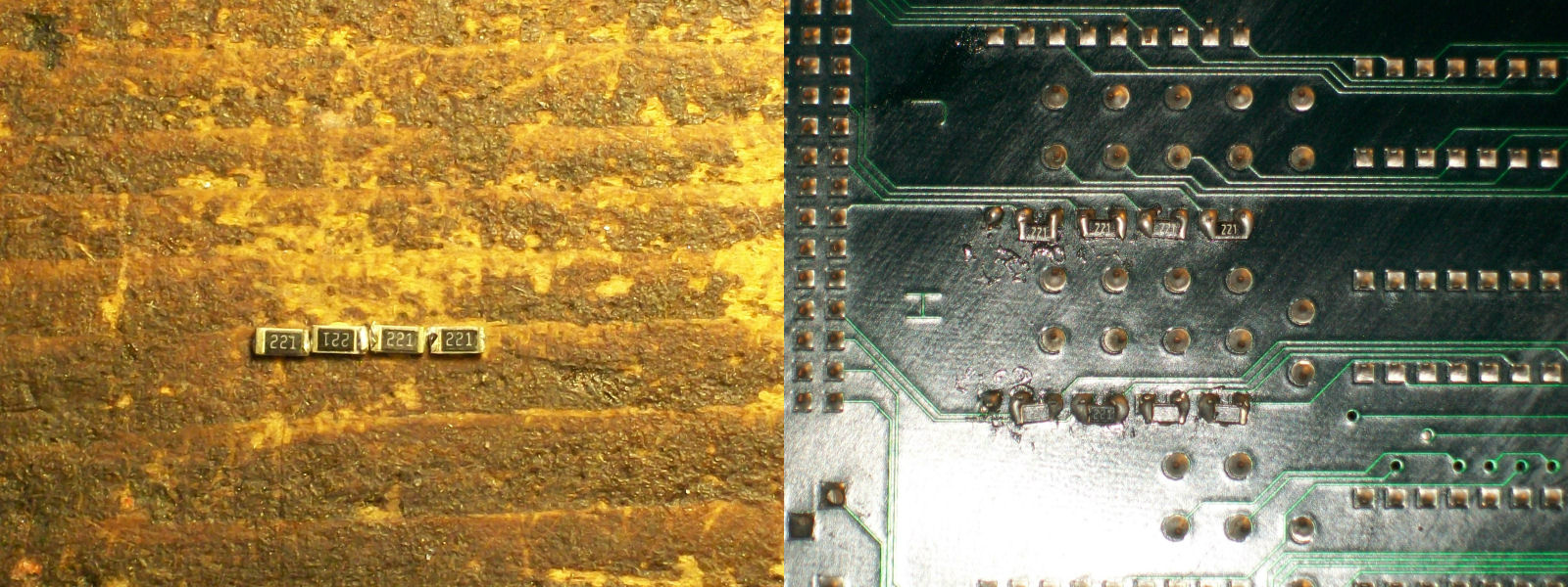
After fitting a good amplifier and all the missing capacitors, the video and sound were perfect but other two issues were present : the controls didn’t work and sprites were glitched.As for first issue, it was due the fact someone replaced a couple of custom resistor arrays with normal 4.7Kohm ones:

100_8542

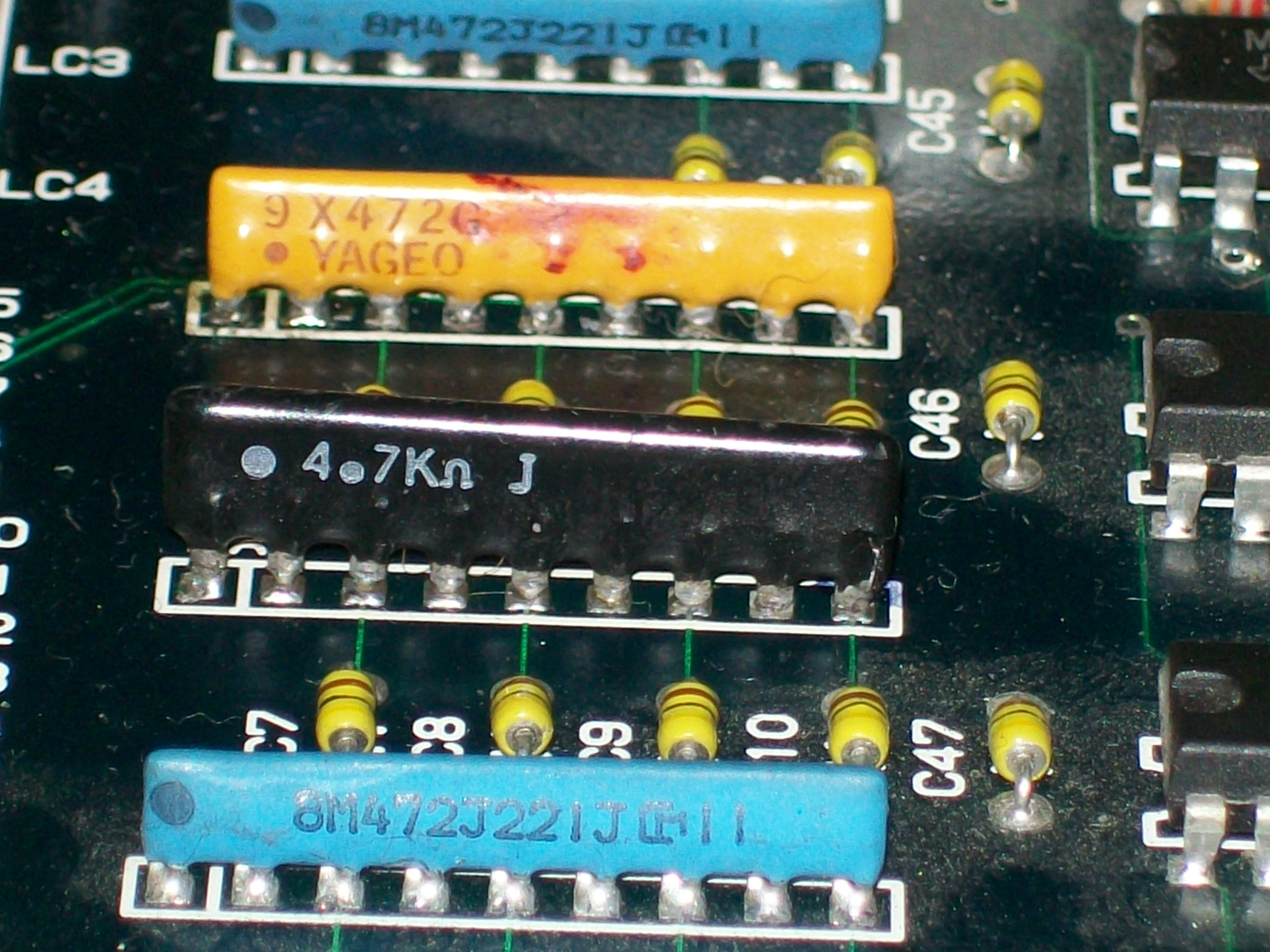
Like the ‘8M472J221J’ part name said, the original array is a mix of 4.7KOhm and 220 Ohm resistors.Not having other spare parts, I opted for a custom solution keeping the 4.7Kohm array and mounting some SMT 220 Ohm resistors on solder side:

220Ohm_SMD_resistors_reworking

This worked perfectly, controls were responding  so I moved on to troubleshoot the sprites issue:

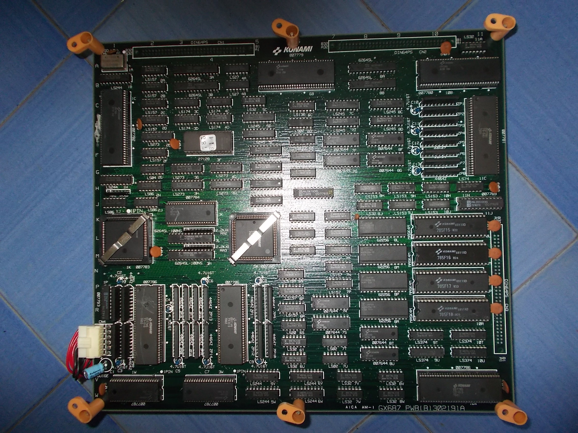
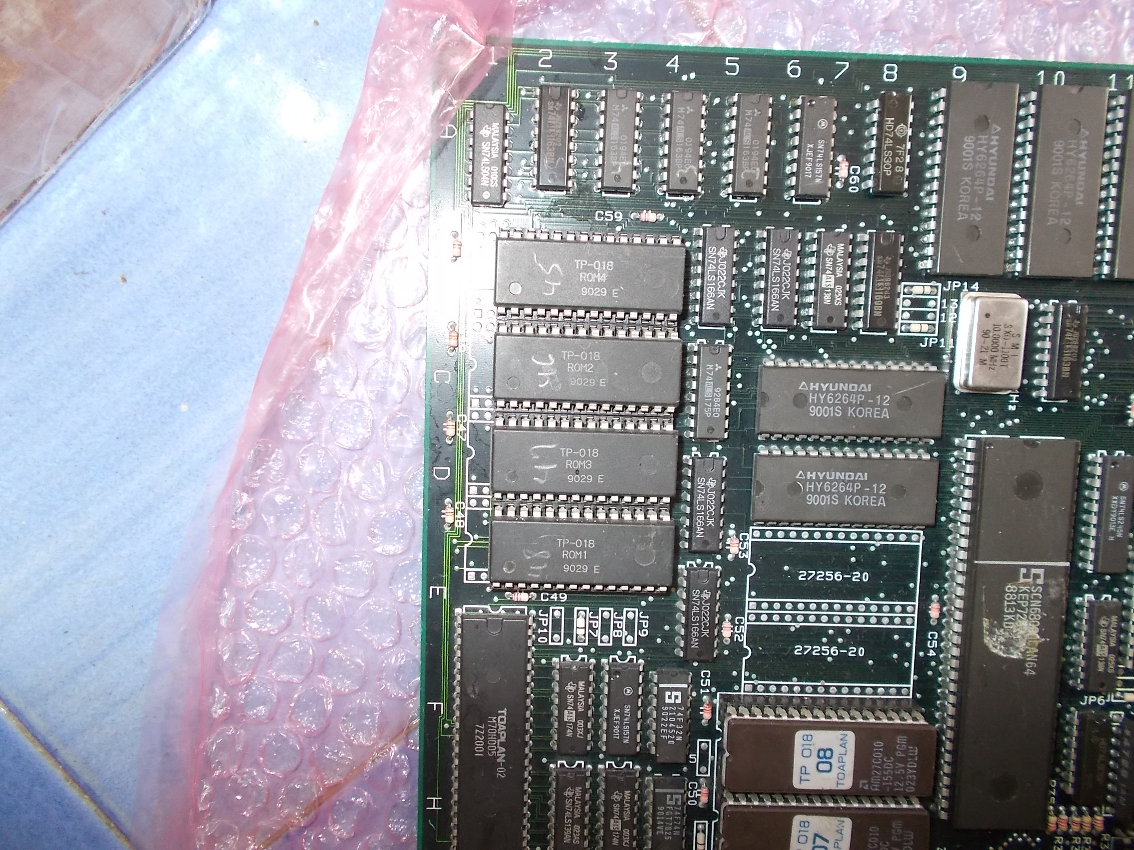
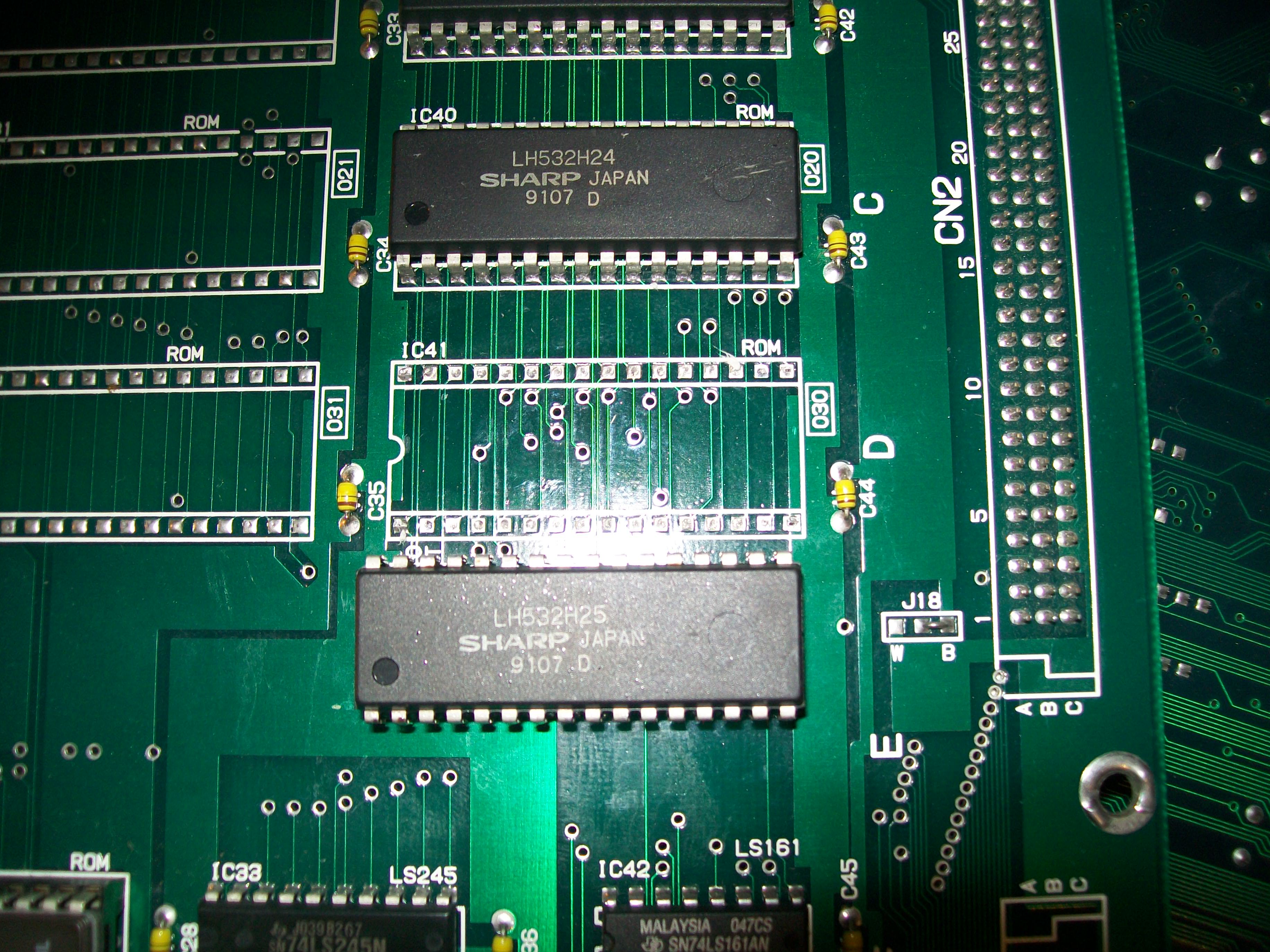
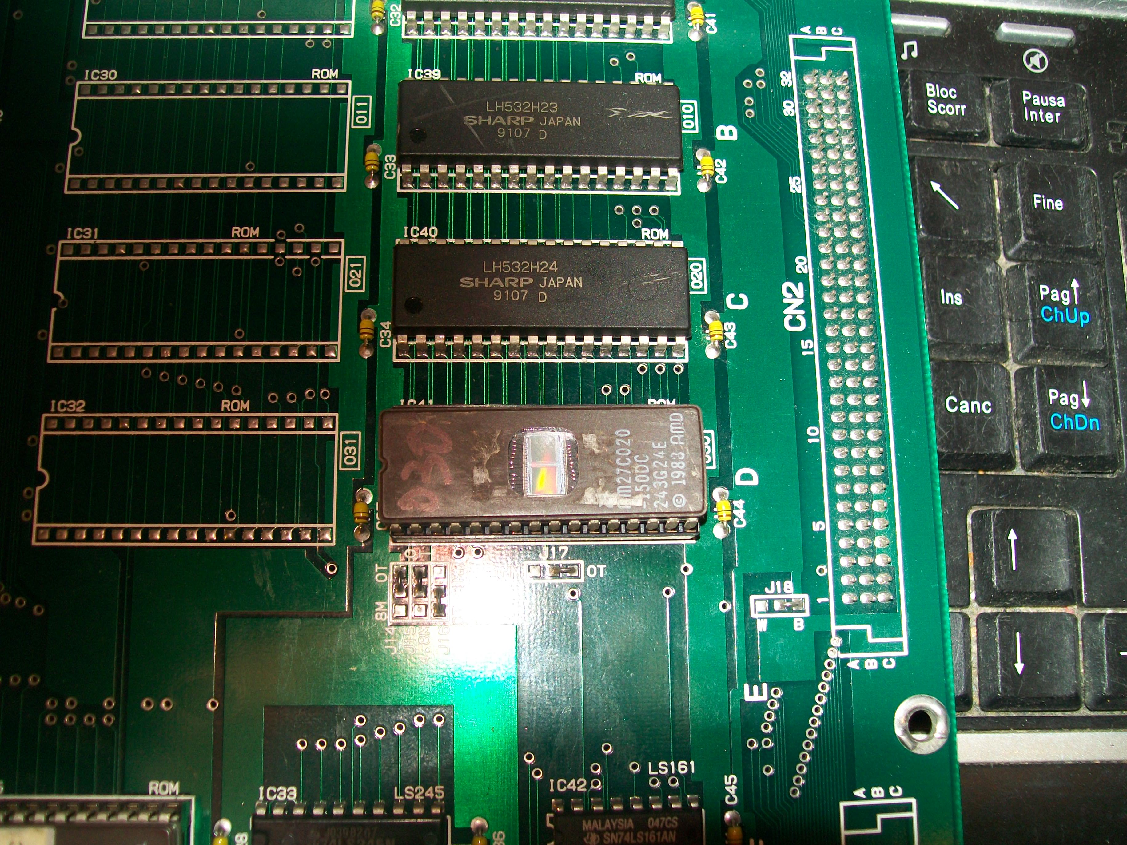
Sprite devices were four 2Mbit MASK ROMs (compatible with 27C020 EPROM) on video board:

100_8549

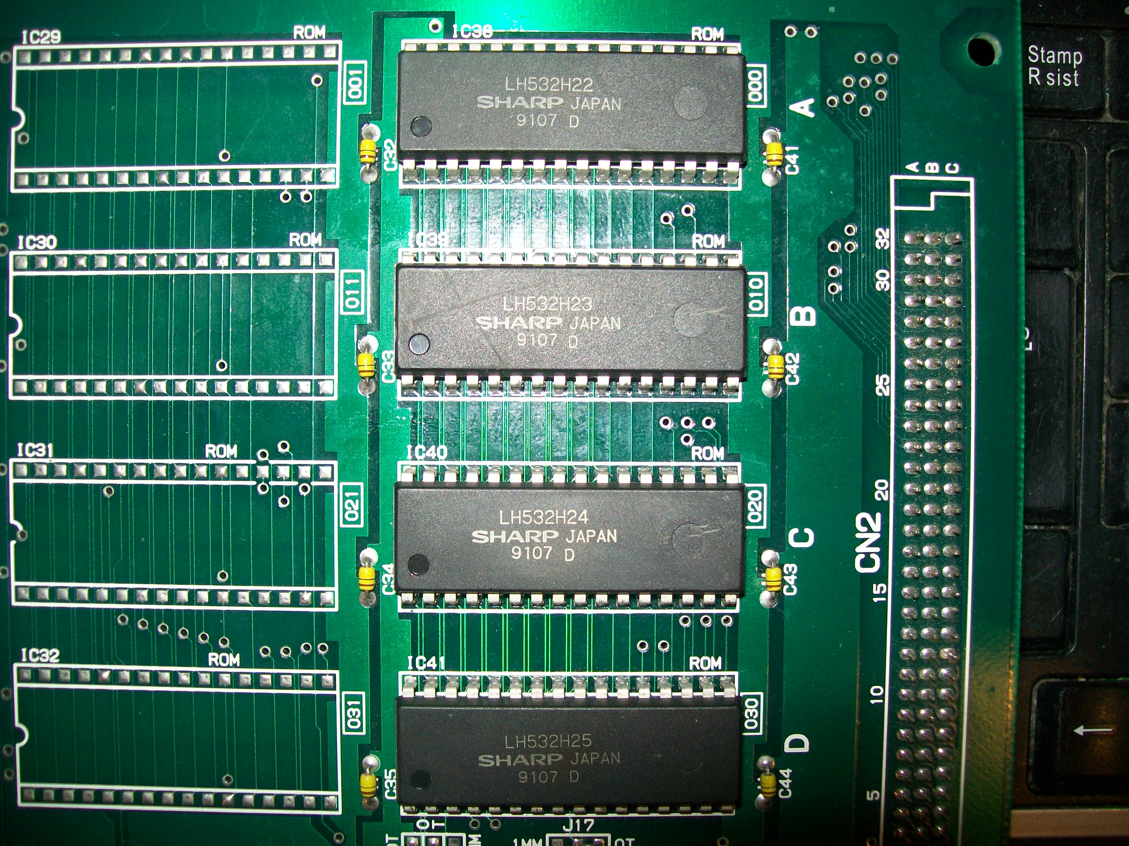
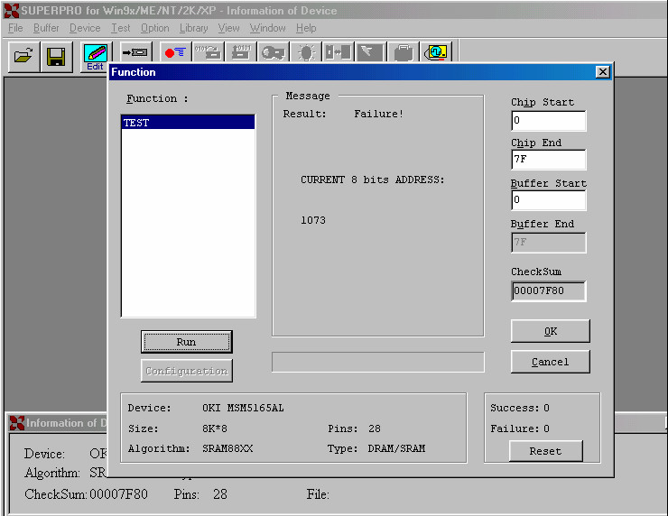
I reprogrammed a 27C020 for each ROM file in order to do piggybacking.When I did it on the one @IC41 glitches vanished.I removed the device:

100_8550

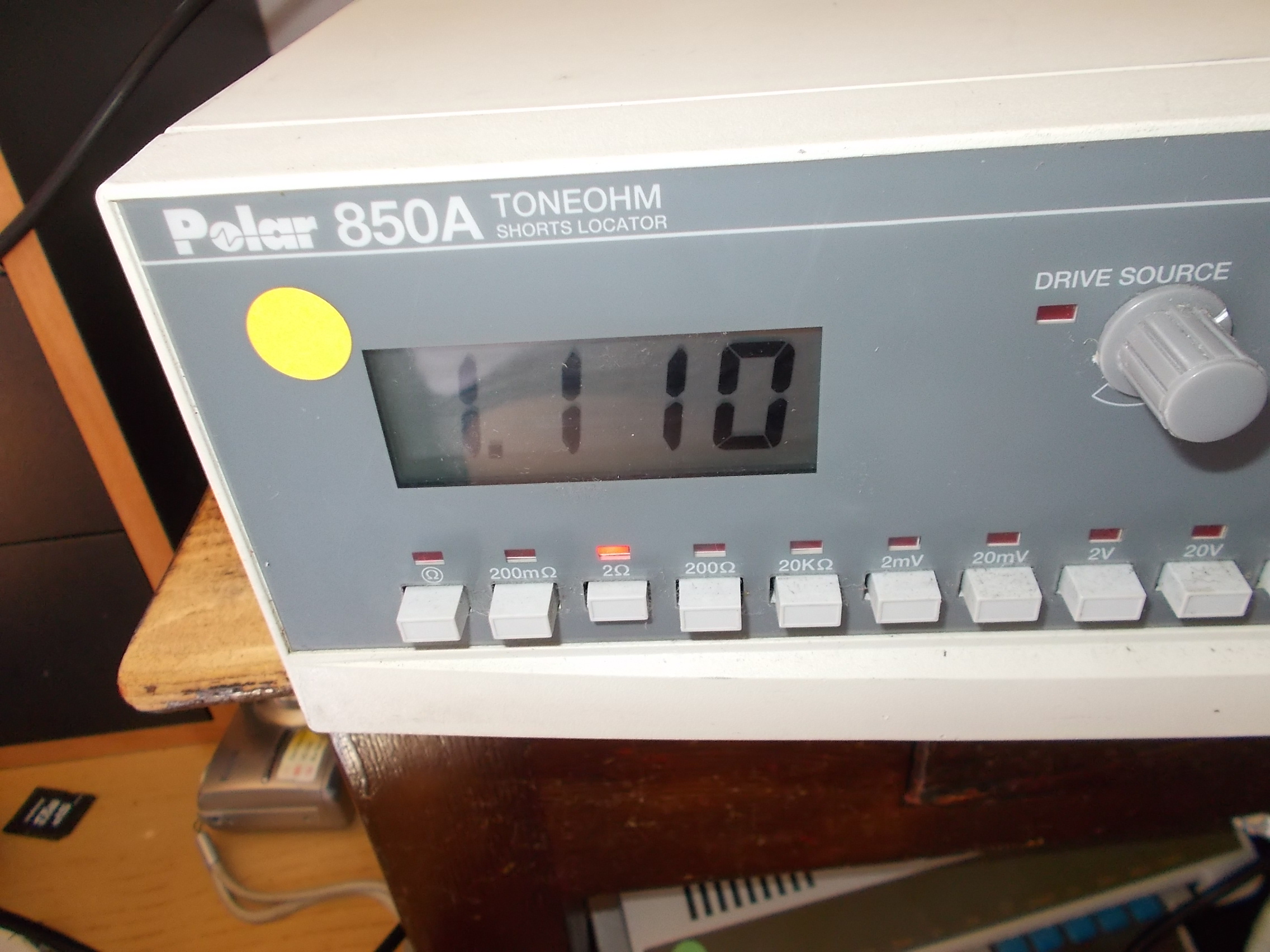
My programmed warned me about a bad contact on pin 31 while I was reading it:

warning_IC41

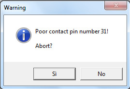
I socketed and replaced it :

100_8553

100% fixed!End of this double Irem repair.

 Posted by at 1:30 pm
Aug 072016
 

Today we have a big Irem PLD update.

The user ‘frsj8112′ sent in dumps from Hammerin’ Harry (M84 hardware) and Pound for Pound (M85 hardware).The two from Hammerin’ Harry are specific to this game and located on M84-C-B board (the middle one) while The Pound for Pound ones are two on CPU board (the middle one) and one on video board (the top one with scratched off customs).All dumps have been successfully tested on GAL16V8 targeting devices.

Besides, he tested on his Hammerin’ Harry PCB the PALs from our archive ‘m84.zip’ we got from unknown source and found that the one named ‘m84-c-3a_ic8.jed’ is the correct one for this board and it’s unique to this game while  the one name ‘m84-a-2h_ic5.jed’ is the same over all the different M84 games.The ones @5L and 7D should be different from game to game.

He also reported feedback on BPROMs.According his tests the bipolar PROM @C37 on M82-B-A VIDEO board can be found also on M84 and M85 hardware although at different location and with different labels.Here’s a reference table fo this BPROM:

  • M72: IC66  (to be verified)
  • M81: IC72  (verified)
  • M82: IC37  (verified)
  • M84: IC21  (verified)
  • M85: IC5   (verified)

Thanks again to ‘frsj8112’ for his work.

 Posted by at 11:18 am
Aug 062016
 

After Lifeforce, another awesome Konami shoot ’em up on the bench, it’s the turn of Gradius II – GOFER no Yabou :

DSCN3879

DSCN3880

Both CPU and video board were in great shape but this is what I got once powered it up:

DSCN3876

Board sat down on the above message and very rarely showed an ‘ADDRESS ERROR’ or ‘ILLEGAL INSTRUCTION’ message:

DSCN3875

Thanks to my friend Josef who sent me a good Gradius II boardset I could narrow the fault in the CPU board but, before knowing this, during my troubleshooting I found with my logic comparator a couple of faulty Fujitsu TTLs, a 74LS32 @7W on video board and a 74LS157 @8G on CPU board  :

74LS32@7W_reworking

74LS157@8G_reworking

TTL_testing

So I could concentrate exclusively on CPU board since I know the fault was there for sure.Probing the board with my oscilloscope I found some abnormal activity on a couple of 6264 RAM @10E and 10G :

10G_10E_data_bus

Launching the game on MAME I could figure out that these two RAMs are used by both the main and slave 68000 CPU :

selftest

So a failure in them would explain the missing boot.Not being able to determine which chip was actually faulty, I desoldered both and added sockets:

10G_10E_socketed

The one @10G didn’t pass the out-of-circuit test failing in address 1073:

6264@10G_failed

Finally the board could properly boot and enter in game but with missing graphics and crashing after few seconds all the time :

Probing around again with my logic comparator I found a 74LS74 @6F with bad outputs, once removed it failed :

74LS74@6F_removed

74LS74@6F_failed

This fixed the board completely, no other issue were present.Evil Konami defeated again.The battle goes on.

100_8491


 Posted by at 10:36 pm

Lifeforce repair log

 PCB Repair Logs  Comments Off on Lifeforce repair log
Aug 062016
 

Received this Lifeforce PCB for a repair:

DSCN4031

Board suffered from a backgrounds issue, screen was filled of blocks of garbage instead of correct tiles.Here a comparison with MAME snapshots.This in the title screen:

title_comparison

This is the in-game :

ingame_comparison

A video for a better understanding:

The hardware uses the famous ‘GX400’ video board :

DSCN4032

The peculiarity of this board is the lack of ROMs, all the graphics is generated by logic of TTLs and custom ASICs.Anyway I has a good starting point since the owner assured me the customs were all good so the problem was TTL related.So I started to check for abnormalities with my logic probe.All was good until I found some 74LS157 with stuck inputs.According schematics they come from a 74LS273 @12B:

74SL273@12B

As you can see this TTL latches data bits from a 6464 SRAM  @15B which is addressed by the custom ‘0005291’ @20D (probably a tilemap generator).Probing it with a logic analyzer confirmed the outputs were all stuck low or high (only one gate was analyzed but all other were confirmed stuck as well with my oscilloscope) :

74SL273@12B_logic_analysing

So confident I removed it (I forgot, obviously it was from Fujitsu):

DSCN4033

Once tested out-of-circuit, it failed miserably:

74SL273@12B_failed

Fitted a rounded  machine-tooled socket and a good chip:

74LS273@12B_new_fitted

And:

fixed

Once again Evil Konami has been defeated!See you in the next chapter of this neverending battle…

 Posted by at 11:00 am

Out Zone repair log #4

 PCB Repair Logs  Comments Off on Out Zone repair log #4
Aug 032016
 

Another Out Zone PCB (this time on usual ‘TP-018’ hardware) on the bench:

DSCN3960

Board was in good shape but I noticed it was heavily reworked on solderside, a lot of ICs were replaced and PCB was not cleaned from solder flux residuals:

DSCN4039

Besides, some ground pins of JAMMA edge connector were partially missing or burnt (sign that something gone shorted) and a 100 nF mylar capacitor was missing.I promply restored all of them:

DSCN4022

Board booted into game but some sprites were wrong (more than a palette problem it seemed to me an issue related to data bus as if sprites were missing some layers) :

sprite_issue

When I went to read the four 1Mbit ROMs containing relevant data I noticed devices were put in wrong sockets:

DSCN3961

Silkscreening under the sockets clearly tells where these MASK ROMs must be placed:

DSCN3962

But also with ROMs in correct position some sprites were still wrong.I started to test the part of circuit involved in sprites generation and all was fine until I came across two data lines shorted on a 6264 RAM @10A :

DSCN4006

The two data lines are connected to the sprites generator custom ‘FCU-2’ and to inputs of a couple of 74LS374 so the short was present also on them.Lifting a pin of the custom didn’t clear the short.

DSCN4044

Obviously due the not high resolution of a simple multimeter I could read always a dead short on each of this component.So I decided to use my Polar Toneohm 850A short locator (essentially an audible milliohmmeter) in order to locate the minimum resistance point.

1,110 Ohm measured on the two shorted data lines (pin 12 and 13) of the 6264 RAM @10A:

DSCN4007

Around 700 mOhm measured on the two pins of the custom ASIC ‘FCU-2’:

DSCN4009

19.3 mOhm on the 74LS374 @19E

DSCN4012

17.2 mOhms on the 74SL374 @19C and beep was squeeling at higher frequency :


DSCN4011

So I was approaching to the short, it was in the area of the two 74LS374.On part side I didn’t notice anything abnormal so I went to inspect the solder side and after some time I find the culprit:

pin13-pin14_74LS374@19C_bridge

Two pads connected to  inputs of the two 74LS374 were bridged, a ‘kind’ gift of previous repairer.I warmed up my soldering iron and removed it.Powered up the board again :

fixed

Board 100% fixed.Mission accomplished.


 Posted by at 11:27 pm