Caius

Mar 122018
 

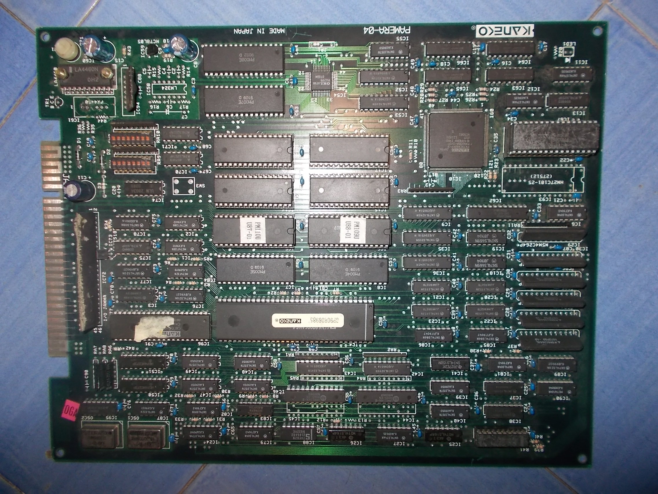
Picked up recently this cheap untested Gals Panic PCB (MCU protected version)
When powered up I was greeted by this :
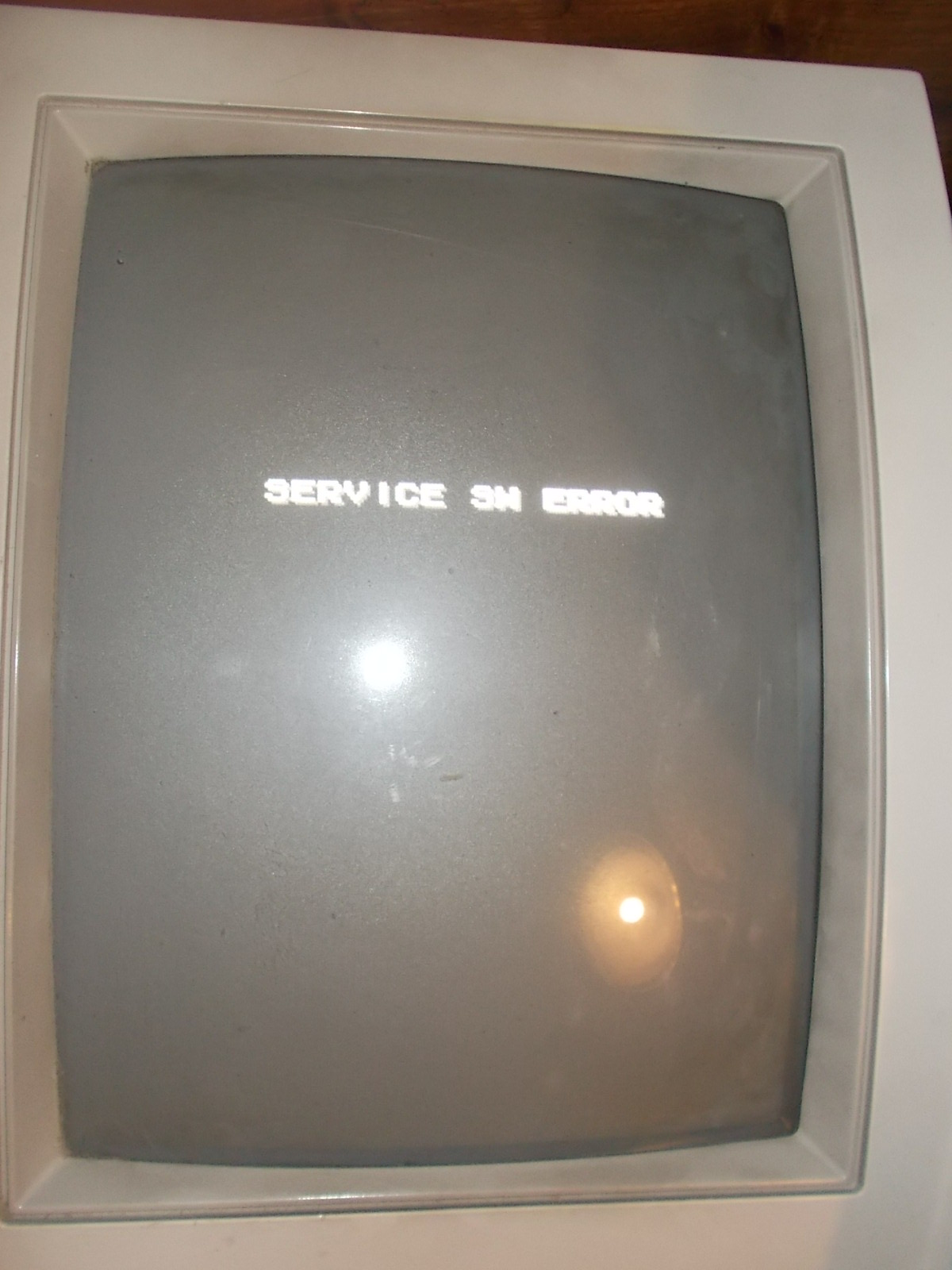
All inputs (including SERVICE one) are handled by a custom in SIL package marked ‘MC-8282’ (found also as ‘MC-1091’ in other boards from Kaneko)
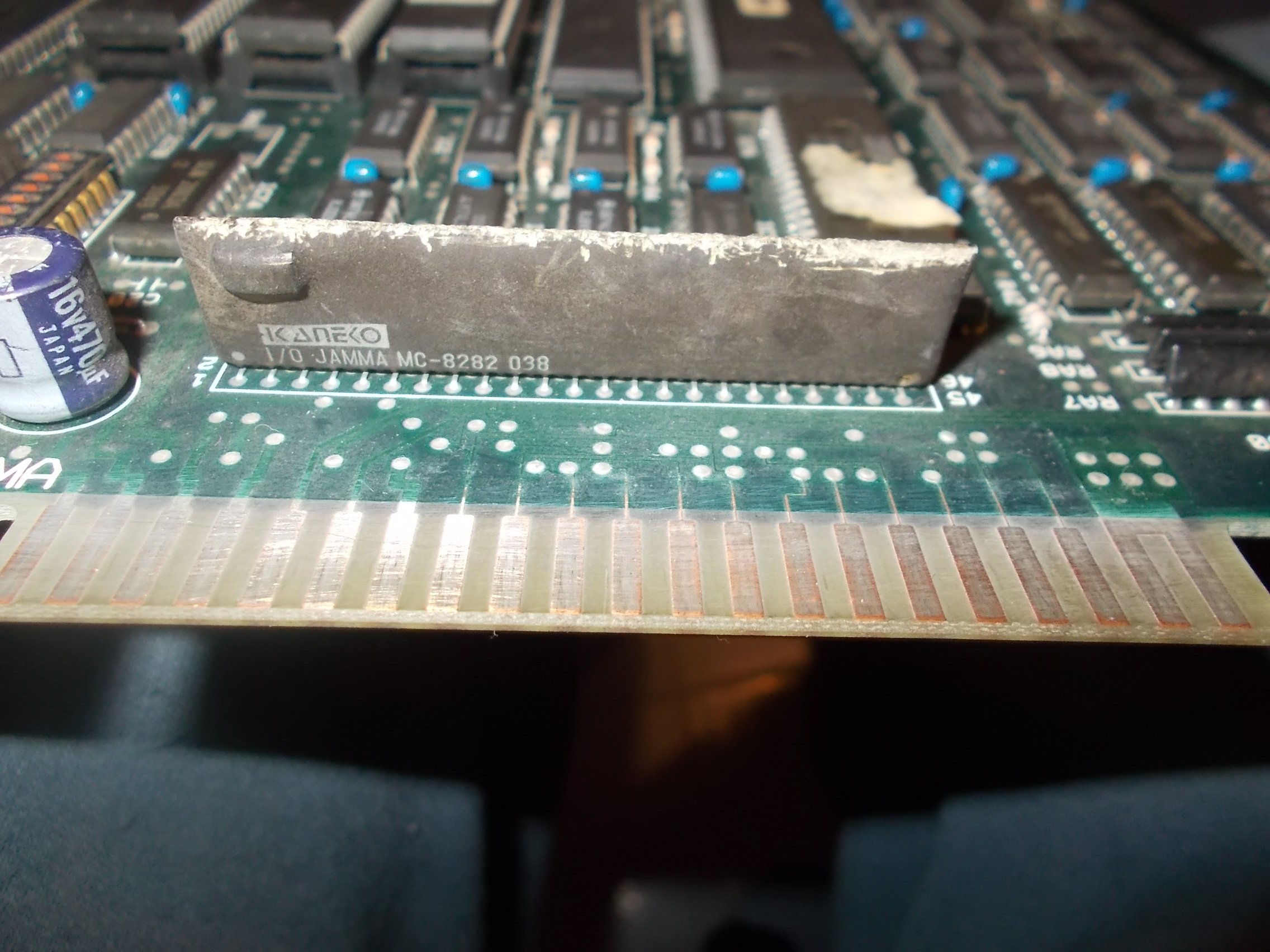
I’ve already discussed the topic in my past post about the reproduction of this custom:

Kaneko ‘MC-1091/MC-8282’ reproduction

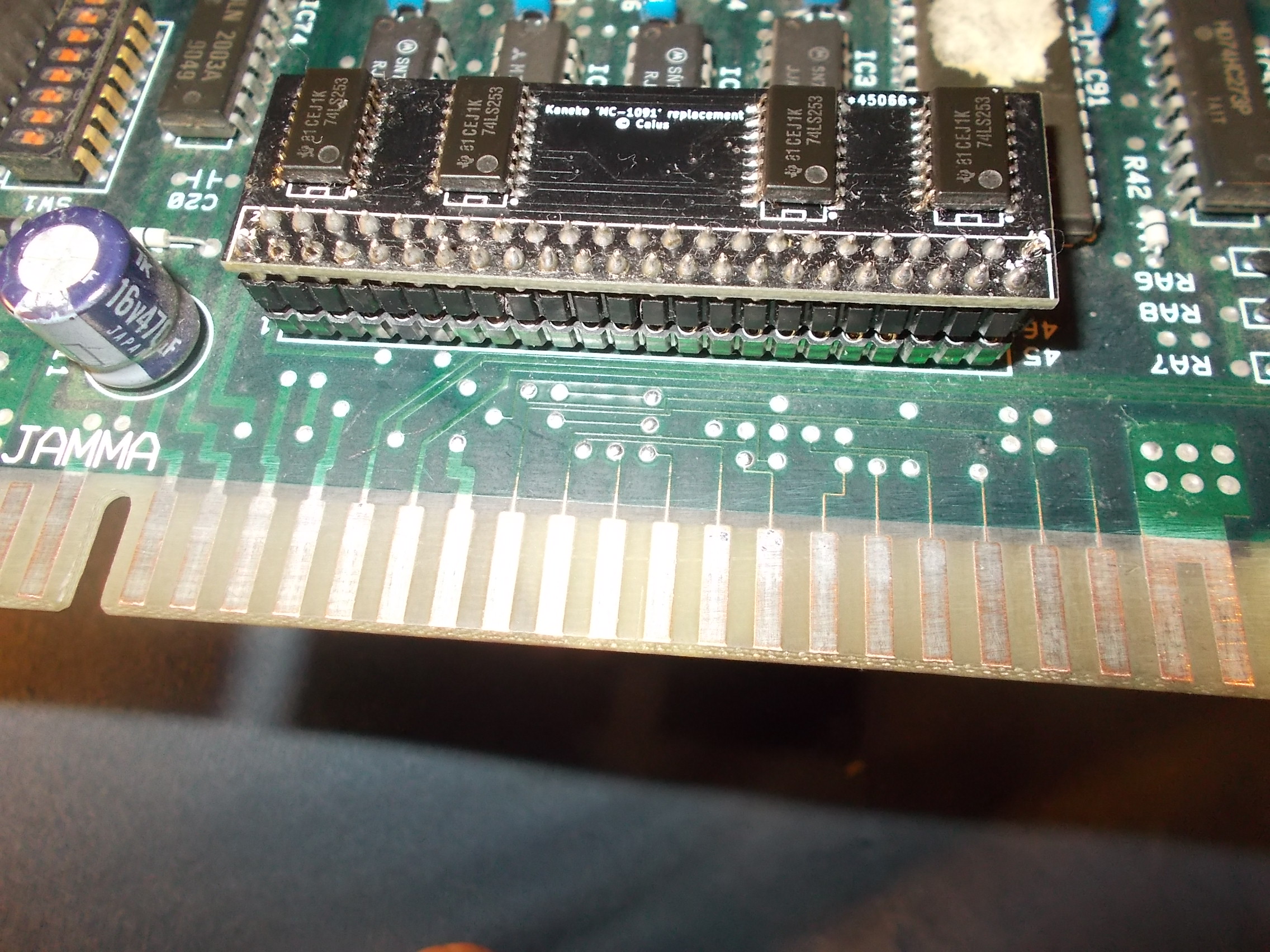
Most likely the component was internally faulty so I replaced it with a repro of mine:
Finally the board booted into game but the sound was barely audible also at maximum volume level:

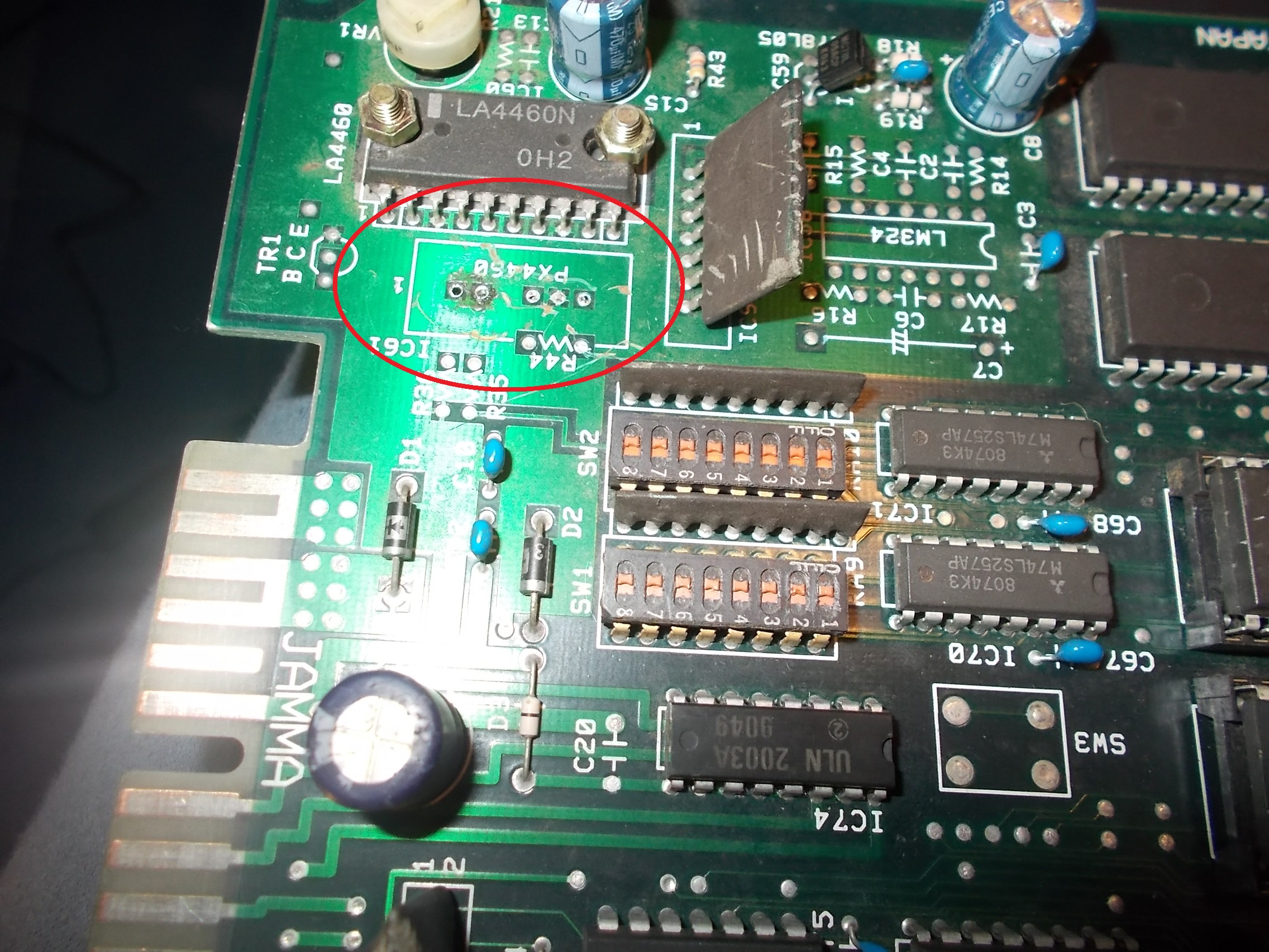
After a visual inspection I found that the component silkscreened ‘PX4460’ was missing from sound section:
Board uses also another little sound custom, the “LPF6K”, here is a picture from another board for better understanding:
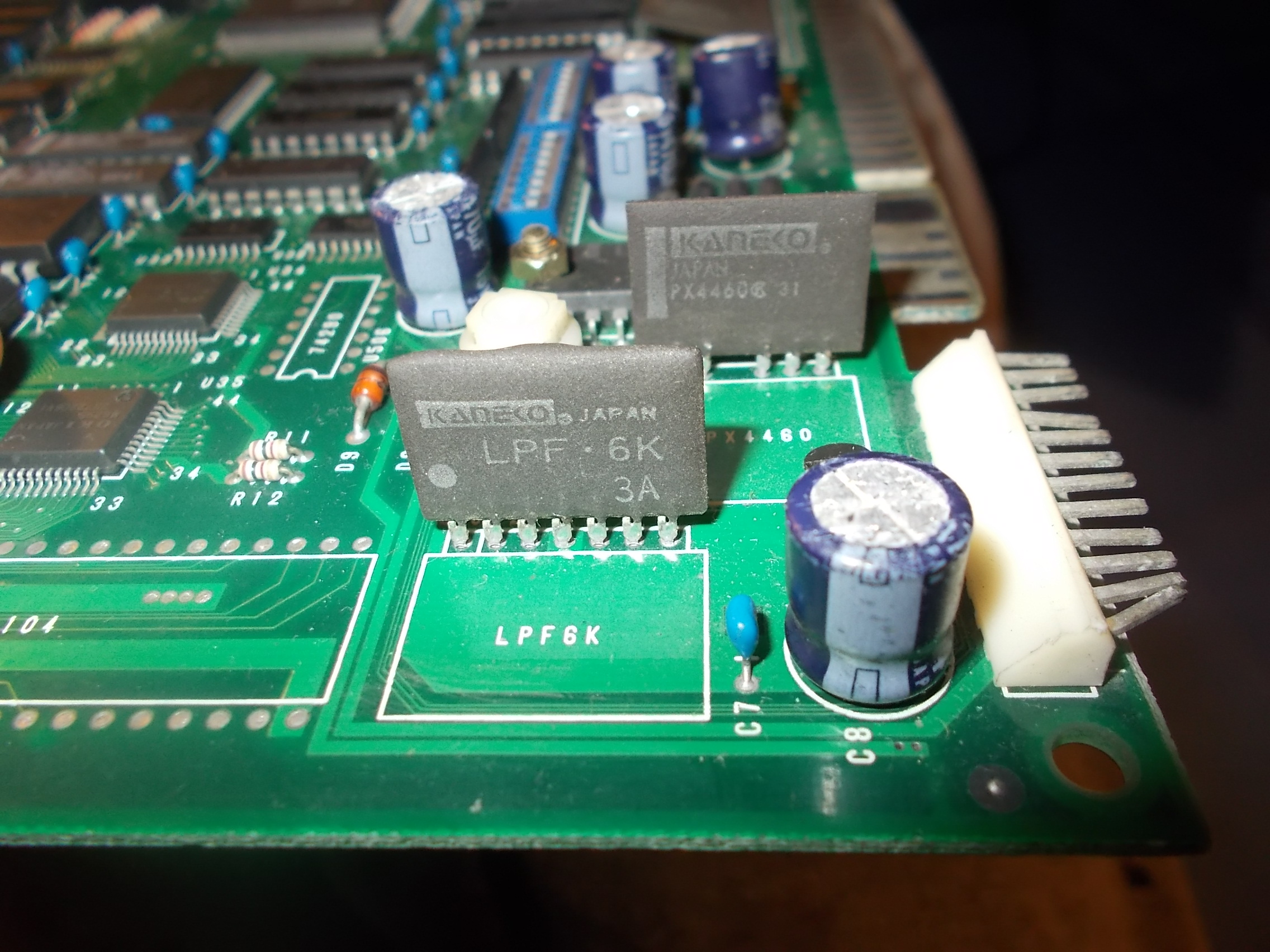
Actually you can replace them by installing the parts they are internally made of directly on PCB (there is silkscreening for them) but I wanted to keep the all-in-one solution the so I decided to have a look inside them in order to reproduce both (although the ‘LPF6K’ was not missing on my board).I removed the coating and did an Hi-Res scan;
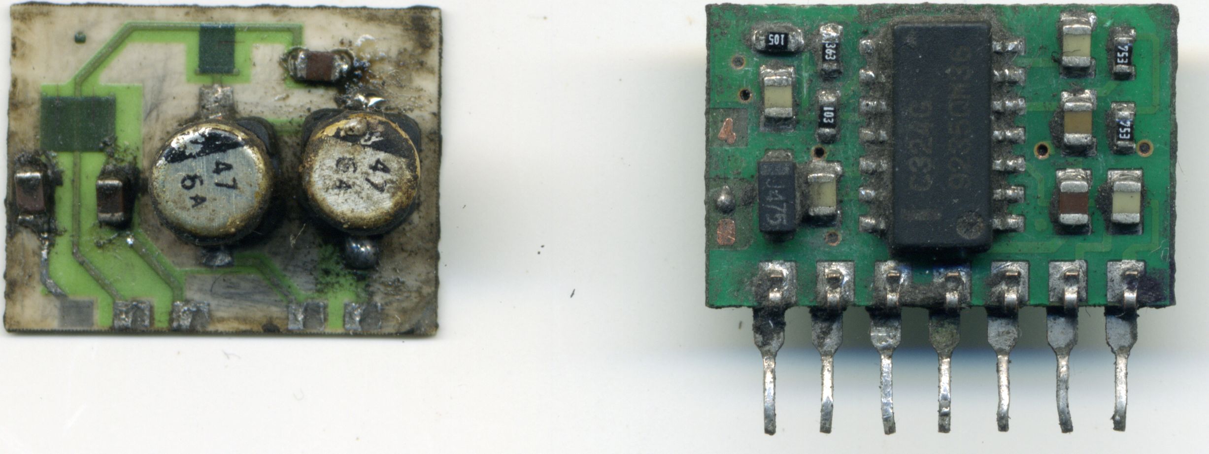
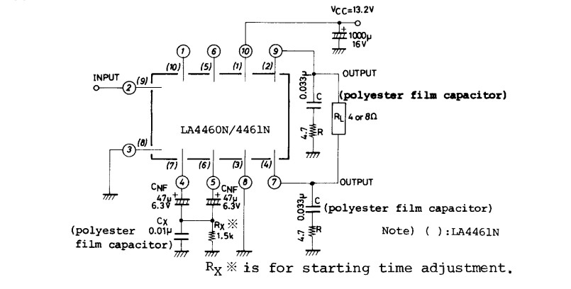
On the left on the above picture it’s the naked ‘PX4460’ which, like its name suggests, embeds all the parts (minus the 1000uF 16V electrolytic capacitor, this is on the PCB) needed by the typical application circuit of the ‘LA4460’ amplifier as datasheet shows :
On the right of the scan, it’s the ‘LPF6K’ that contains an LM324 OP-AMP  and all its required parts, its function is to pre-amplify the sound.

Given the simplicity of both customs it took few time to figure out schematics and route them to a replacement PCB.Here is the result:
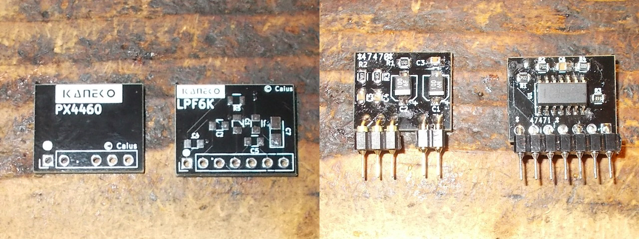
Installed on PCB ready for the smoke test:
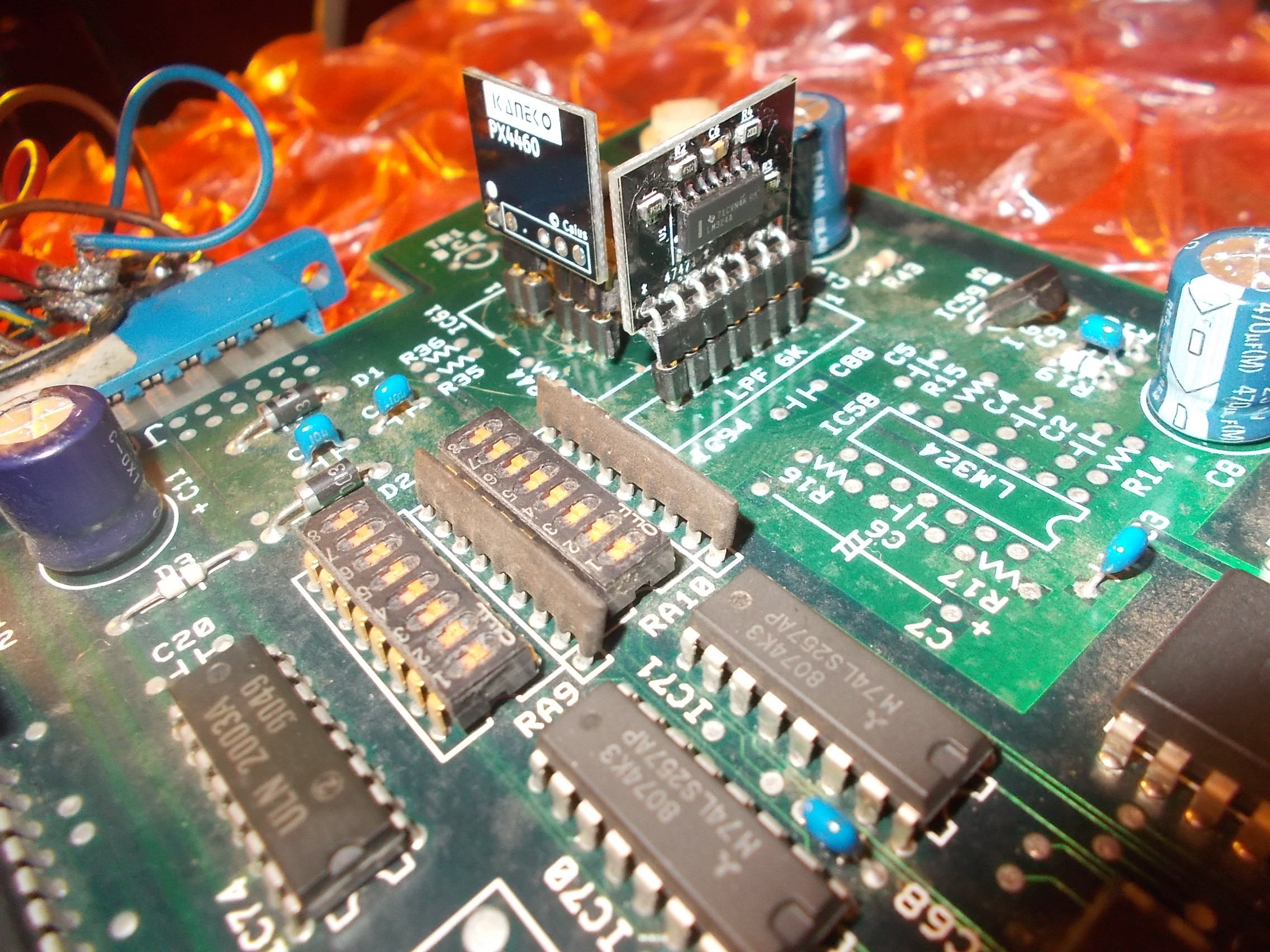
Success!Sound was restored and both repro worked fine as replacement.

 

 Posted by at 11:10 pm
Mar 092018
 

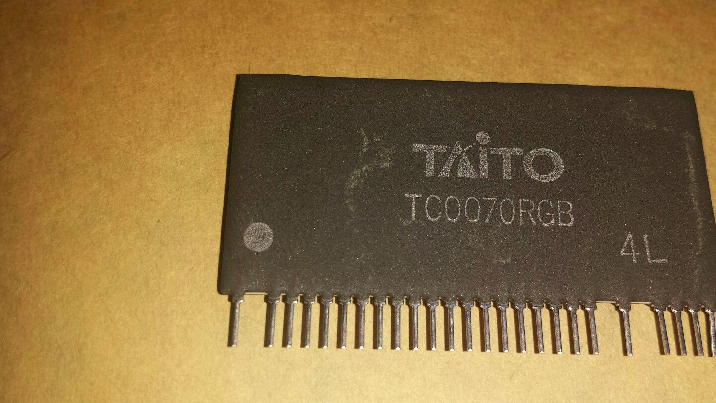
The ‘TC0070RGB’ is a 15-bit RGB DAC (5-bit for each color) used in many PCBs from Taito : Rainbow Islands (Normal and Extra version), Bonze Adventure, Cadash, Continental Circuit, Chase HQ, Operation Wolf, Final Blow, Ninja Warriors just to name few.As many custom RGB DAC of its era it comes in SIL package (picture taken from the net) 

I will not go into the technical details since the component has been already analyzed and schematics figured out as well as a reproduction has been excellently realized by Macro (who embedded all logics into two GAL devices) :

https://www.ukvac.com/forum/taito-tc0070rgb-replacement_topic335848.html

https://www.macros-arcade.com/Taito-RGB.html

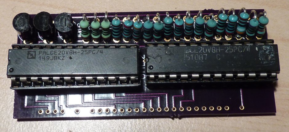
Here is how his repro looks like:

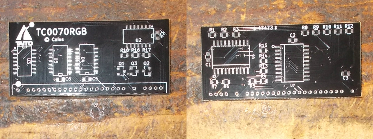
What I have done is I simply reproduced the ‘TC0070RGB’ in my way trying to stay as much close as possible to the original design while keeping the same dimensions, color and parts used.The result is quite pleasant:

Testing on a Rainbow Island Extra PCB :

See you all to my next reproduction project!

 Posted by at 4:04 pm
Mar 082018
 

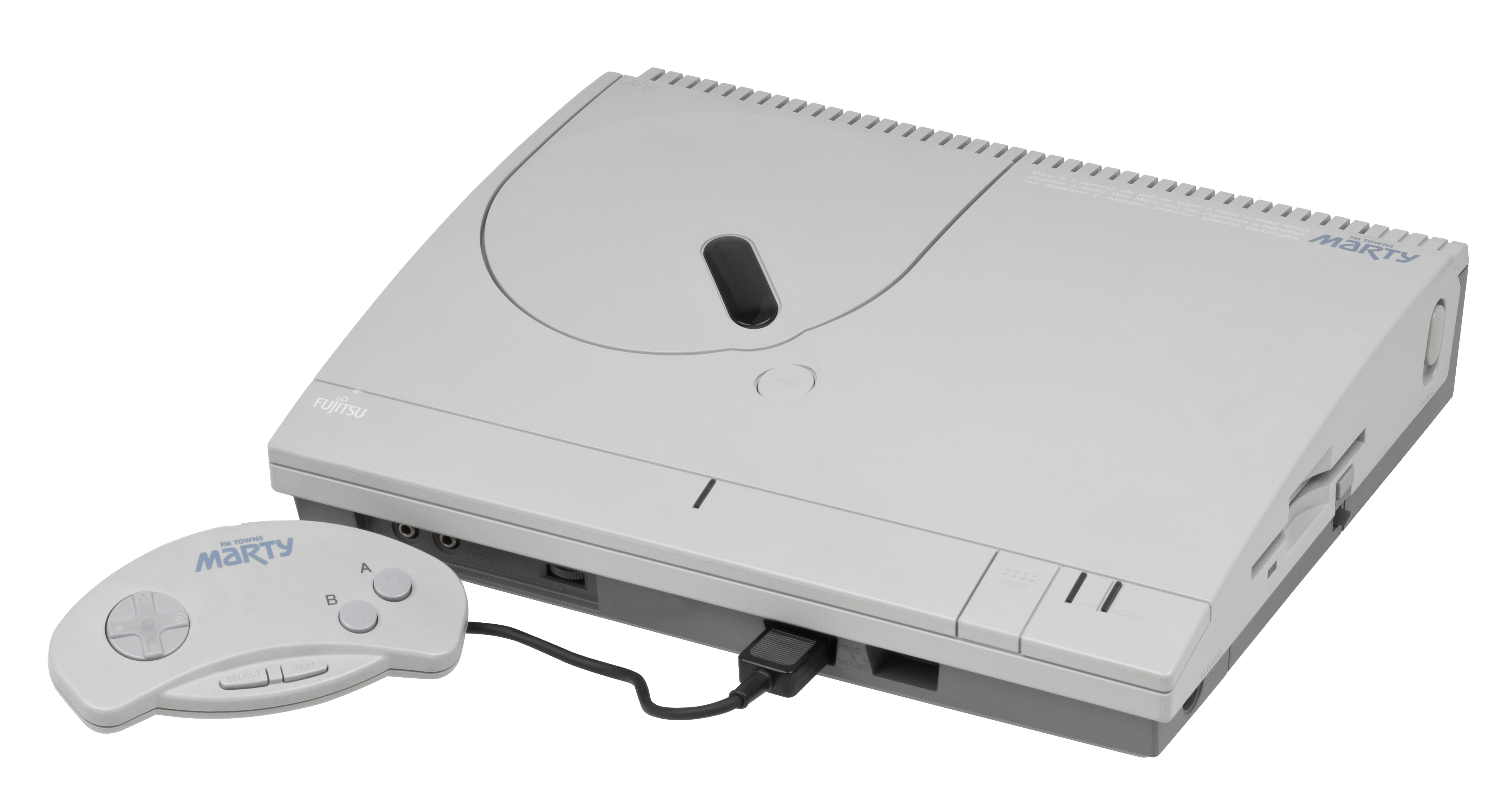
As many of you collectors/enthusiasts may know, the FM Towns Marty is  is a  home video game console released in 1993 by Fujitsu, exclusively for the Japanese market. It was the first 32-bit home video game system, and came complete with a built in CD-ROM drive and floppy disk drive (able to read 1.2MB formatted disk like other japanese systems). It was based on the earlier FM Towns computer system Fujitsu had released in 1989. The Marty was backward-compatible with older FM Towns games :


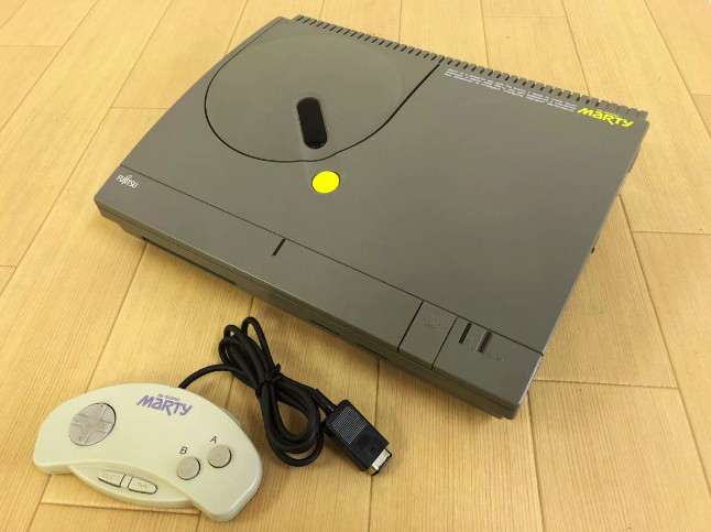
A later model called Marty 2 was released in 1994 but it was essentially the same hardware (darker grey shell apart)

Game list includes many Japanese versions of great PC games, such as Indiana Jones and the Fate of Atlantis, Wing Commander II, Ultima VI, Monkey Island II, and so on.But this console is well known also for having many arcade-perfect ports like Splatterhouse, Tatsujin Oh, Raiden, Super Street Fighter 2, Viewpoint and other.Most of its software is on bootable CD-ROM but some games require both a CD and a floppy disk, so even if a burned CDR is used, a correctly formatted floppy is also required.Sadly the floppy drive is a weak point of this console, in best of cases the drive belt may melt over time but the unit is considered fragile and no spare are available.Luckily nowadays FDDs can be replaced by emulator and in this article I will explain how to use an HxC SD floppy emulator (by Jean-Francois del Nero) in a Marty (or Marty 2 like mine) console.

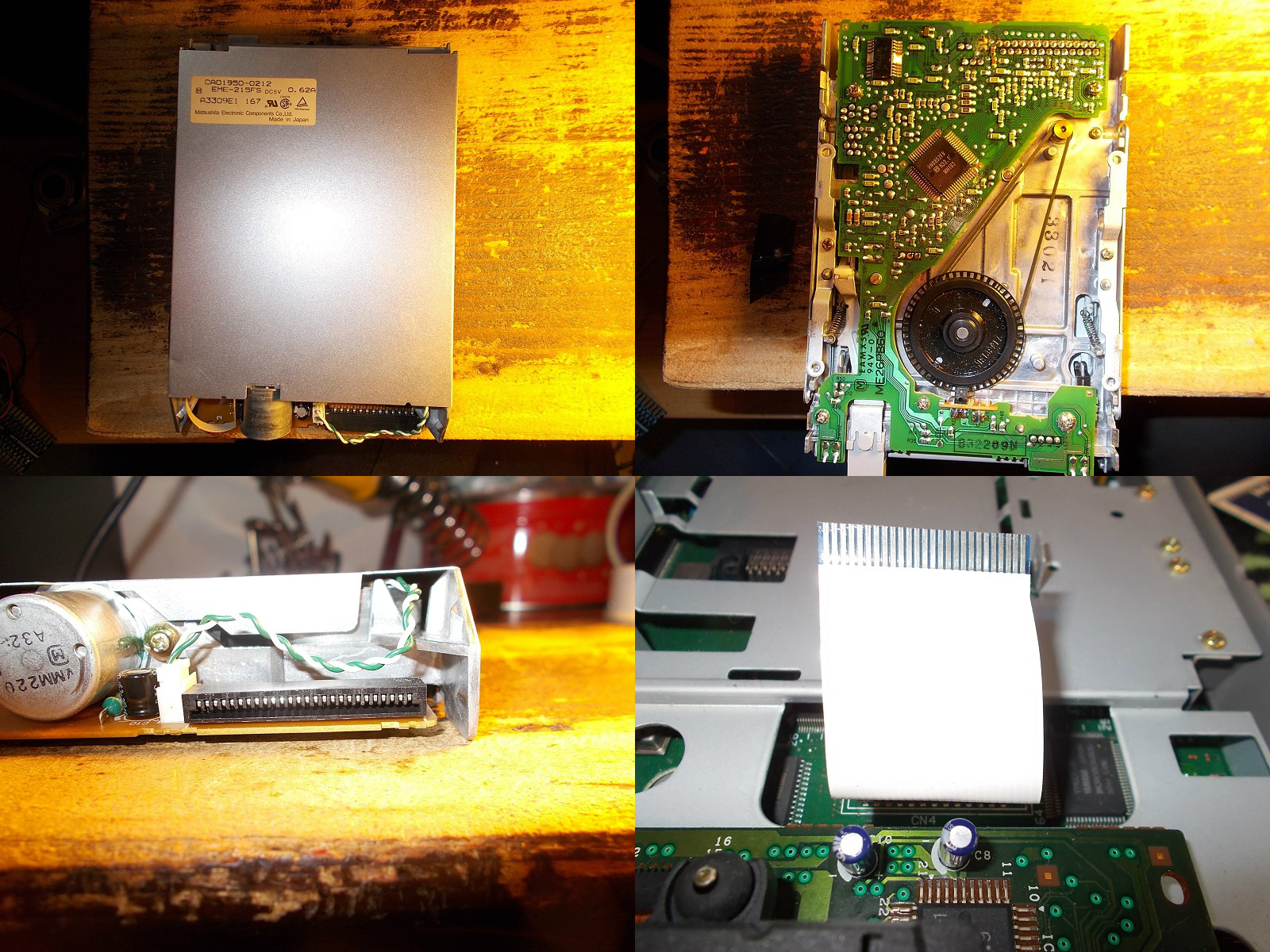
The original FDD of the FM Towns Marty console is a EME-215FS manufactured by Matsushita with a 26PIN FFC connector and cable (1.25mm of pitch) :

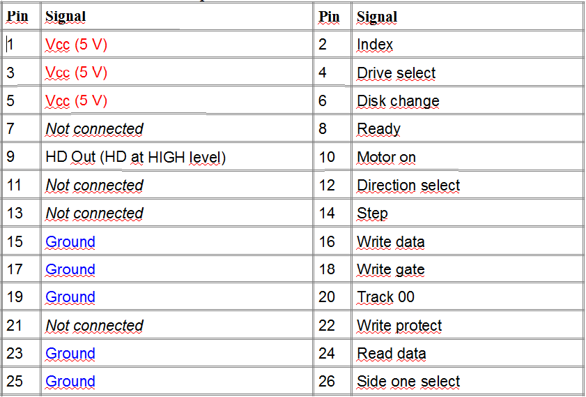
No info were available about so I first analized it and came to the conclusion that its pinout was the same of a slim 26PIN FDD for PC which comes with a FFC connector too but pitch is 1.00mm ( pin 13 and 21 are GND on Marty)

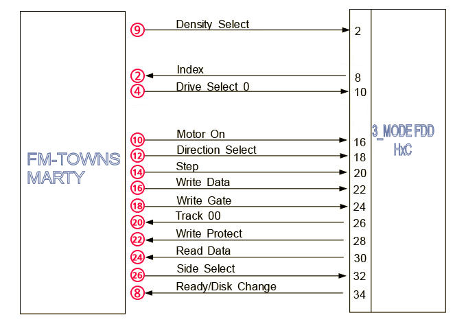
Based on the above pinout I figured out the connection diagram to the HxC (or a real 34 pin FDD able to handle 1.2MB formatted disks)

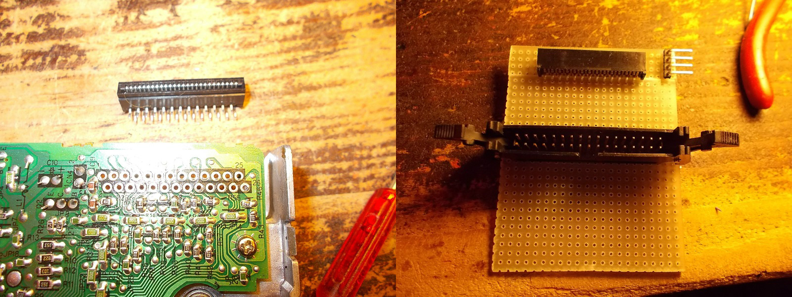
Obviously some kind of adapter was needed.Not having a spare 1.25mm FFC connector I ended up to remove the one from original drive and build an adapter to 34 PIN IDC (the 4 pin connector is for powering the HxC) :

I carried on the first test on a Samsung SFD-321B FDD (modified to work as Shugart drive) and it worked, I  was able to read/write/format 1.2MB 3.5″ floppies :

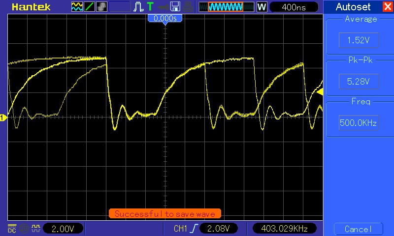
But I was not able to do the same with the HC floppy emulator.After some emails exchanged with Jean-Francois del Nero (a.k.a. Jeff, the designer of the HxC) we found the issue.The READ DATA signal (output from pin 30 of the HxC) was quite slow to rise up in his opinion:

He suggested me to install a 220 Ohm pull-up resistor between pin 30 and +5V (actually FDD outputs are already pulled-up with 2.2K resistors so a further 220 Ohm one put in parallel lowers the resistance to VCC to about 200 Ohm).This corrected the signal to what Marty expected to see:

Doing so finally I got the HxC flopy emulator working with my Marty console!Here are a couple of video I made during reading and formatting operation (sorry for black&white picture but my TV cannot accept NTSC signal)


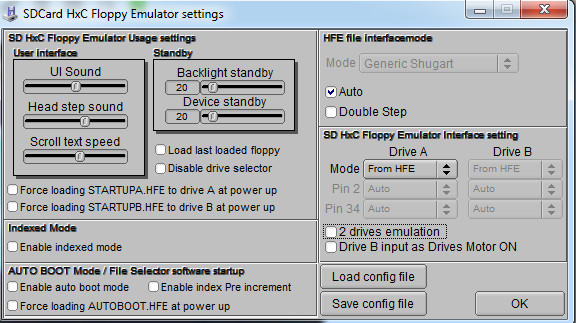
As for the HxC configuration file you can set the interface on “Auto” or ” Generic Shugart” and all other settings on “From HFE”

A big thanks again to Jeff for his wonderful device and support (and patience with me too..).

 Posted by at 3:48 pm

Nastar repair log

 PCB Repair Logs  Comments Off on Nastar repair log
Feb 232018
 

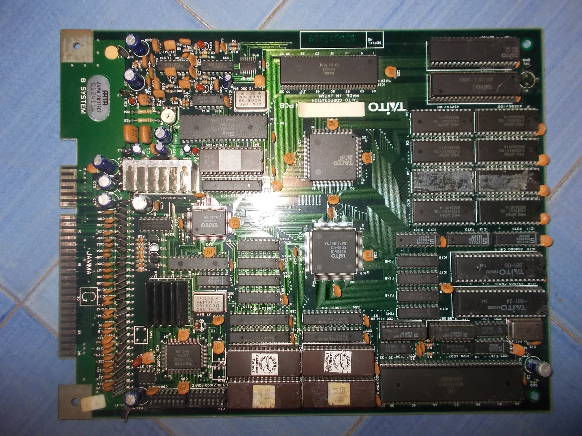
Found this Nastar (on Taito B System hardware) in a lot of faulty PCBs I recently bought:

Board played fine but sound was terribly loud and corrupted :

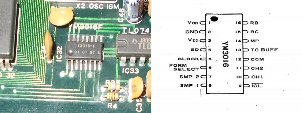
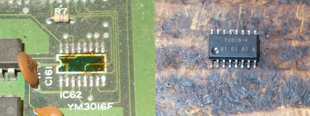
I fired up my audio probe and started “listening” to various points of the sound circuit.Hardware uses an YM3016 DAC (SOP package, always used in conjunction with the YM2610 sound synthesis IC) 


As you can see from the above pinout, its pin 13 (TO BUFF) is the analog output that goes to the pre-amplification circuit (two TL074 OP-AMPs used on this board).”Listening” to this pin confirmed me that sound came out bad from the DAC :

I took a spare from a Football Champ donor board:

Installing it restored a crystal clear sound.End of job.

 Posted by at 12:06 pm

Tricky Doc repair log

 PCB Repair Logs  Comments Off on Tricky Doc repair log
Feb 162018
 

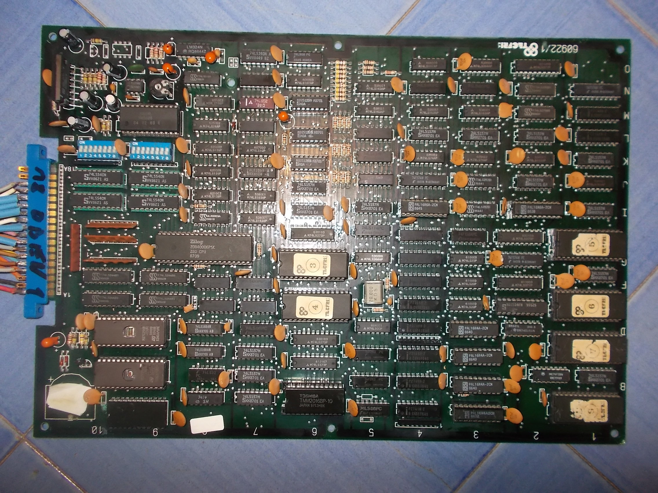
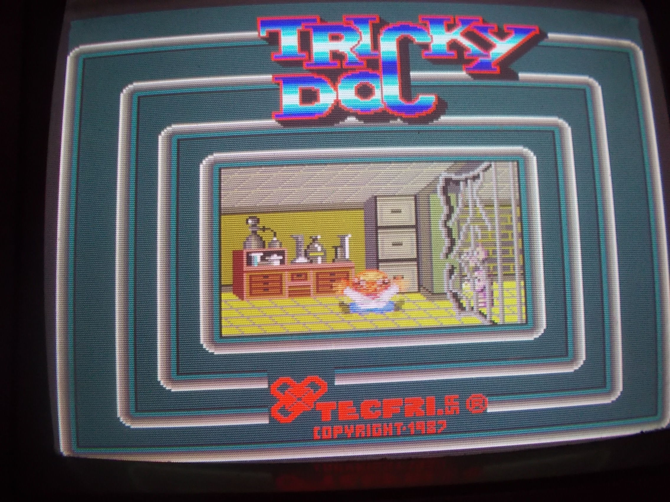
Received from Austria this Tricky Doc PCB for repair, a weird game released by the spanish Tecfri in 1987:

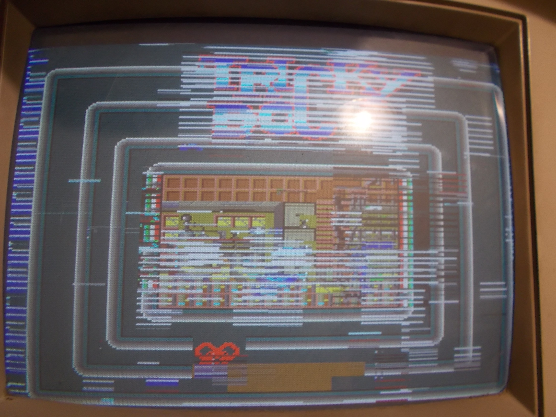
The board had severe graphic faults (and missing sound too)

The faults affected mostly the sprites :

So I went to dump the four devices (27128) that store this part of graphics and I found a bad one :

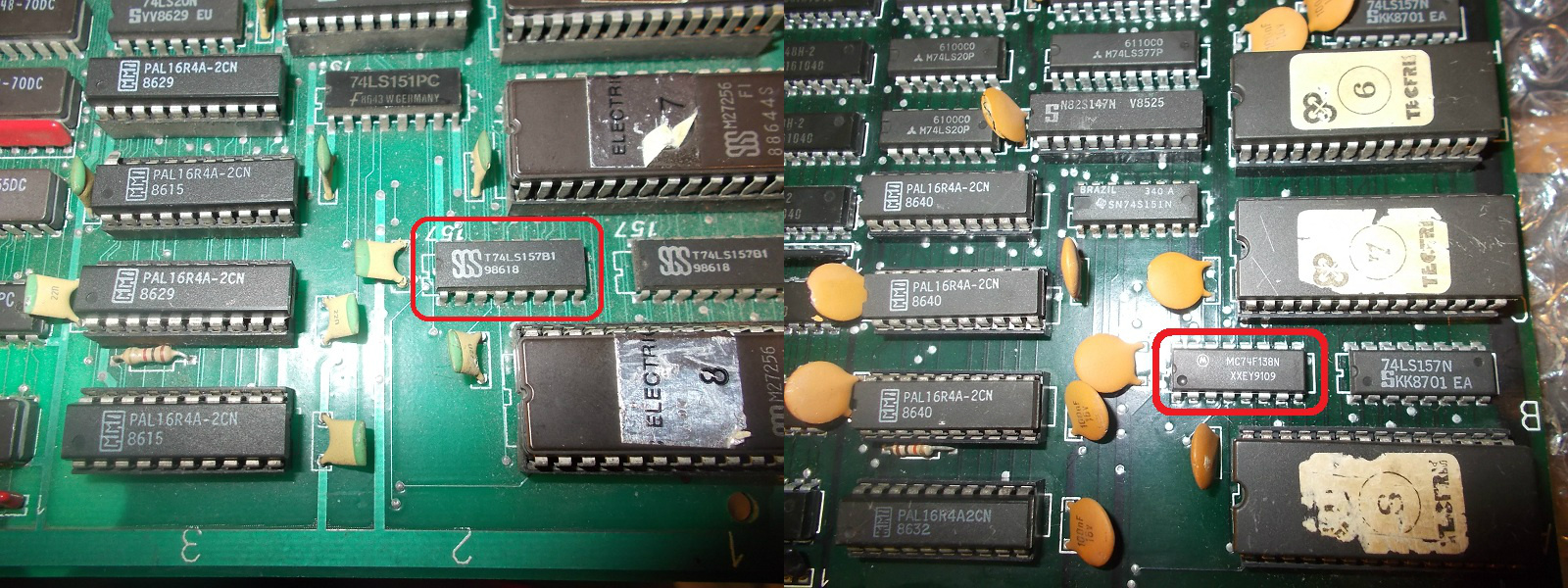
I was checking the sprites generation circuitry when I noticed that some address lines of the ROMs were tied to a 74F138 while all other ones to some 74LS157.I compared the board with a bootleg with identical layout and found that the 74F138 was wrongly installed, actually a 74LS157 must be used instead:

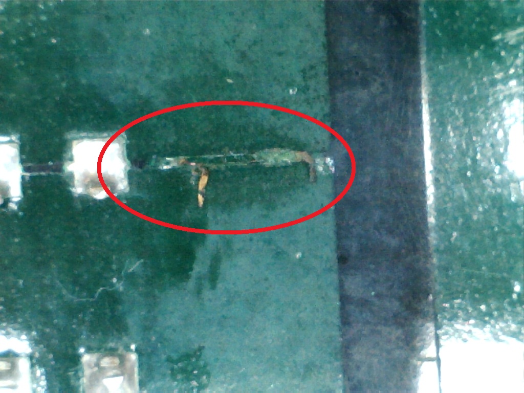
Checking around I found a fried trace that should  have connected to VCC pin 9 (/LOAD) of a 74LS163:

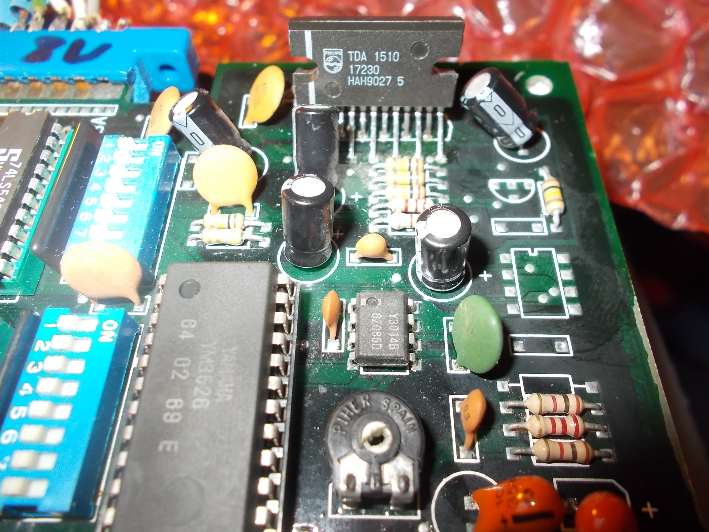
But all these findings lead to little improvement, graphic issue were still noticeable.So moved on to troubleshoot the lack of sound.With an audio probe I found that sound was present before reaching the main amplfier, a Philips TDA1510, but then I got silence on edge connector pins:

It turned out that the amplifer lacked the GROUND connection (so it was no powered) so I added a jumper wire from its pin 7 to a near point.I also installed some capacitance (a 15nF mylar capacitor) between input pin 2 of the amplifier and GROUND to shut down some buzzing noise.

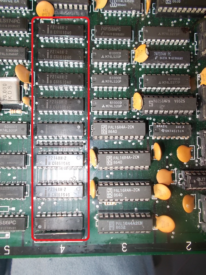
Back to the GFX issue, there is a row of eight 2148 RAMs (1K x 8-bit device) involved in sprites circuit:

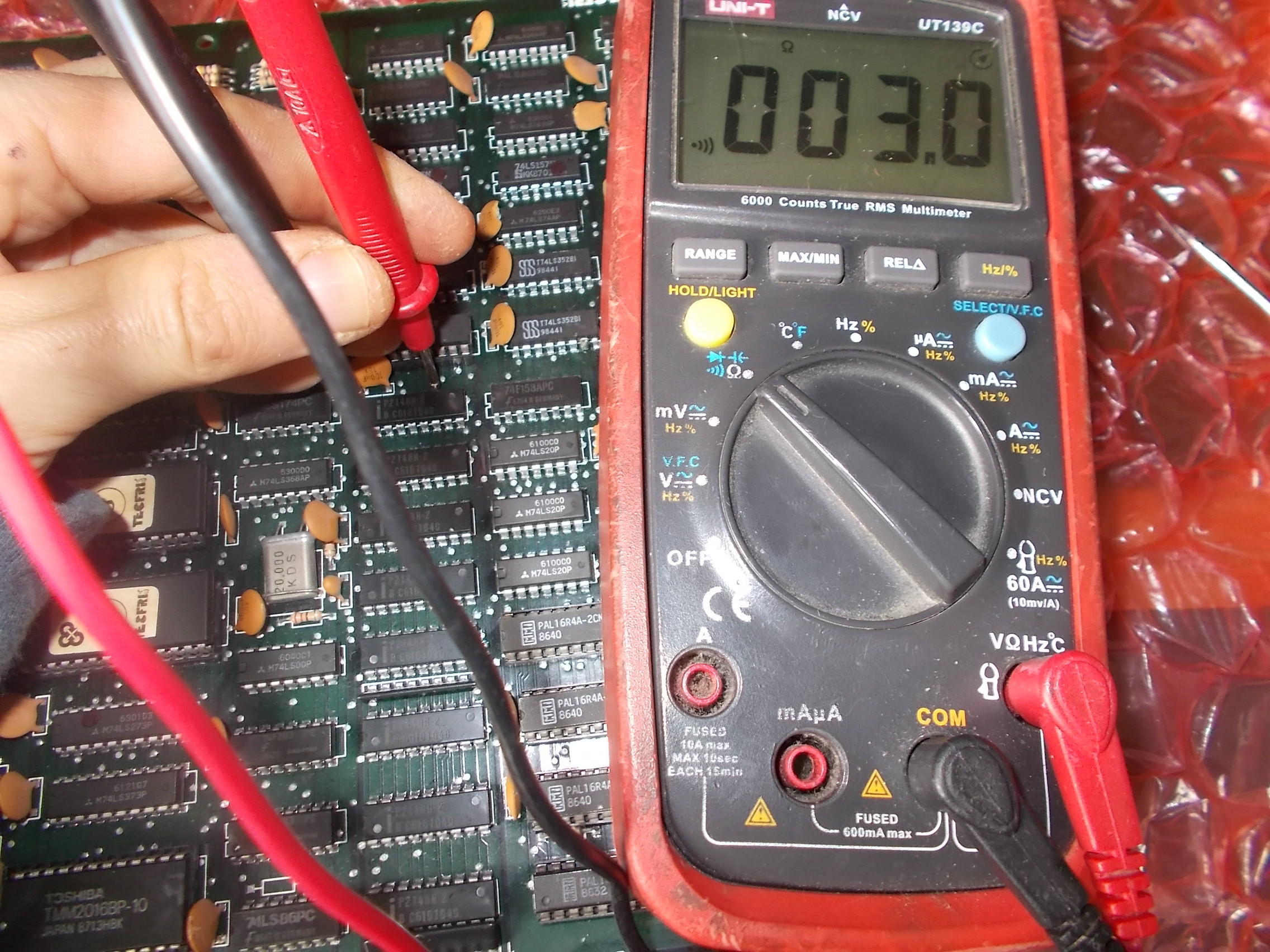
The two on top were really burning hot to the touch.A quick check with a multimeter revealed some data lines were nearly shorted to VCC:

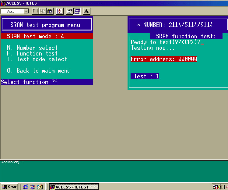
They obvioulsy failed when tested out-of-circuit:

This was the status of the board so far, sprites were still glitched:

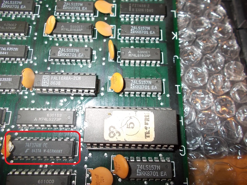
I started to check ICs in-circuit using a logic comparator and doing piggybacking too.When I put a good IC on top of the 73F374 @2G :

the graphics were completely restored:

Probing the IC with a scope revealed the outputs were floating (inputs on the left of the below picture)

I removed the IC and, altough my testers reported it as good, I replaced it.This cured the issue and fixed board completely.As title of the game suggests, it was a “tricky” repair but was worth it in order to salveage a such unusual board.


 Posted by at 9:44 pm