Big Fight – Big Trouble In The Atlantic Ocean repair log

 PCB Repair Logs  Comments Off on Big Fight – Big Trouble In The Atlantic Ocean repair log
Mar 162017
 

Got this rare Big Fight – Big Trouble In The Atlantic Ocean (this is the full title) PCB for a repair :

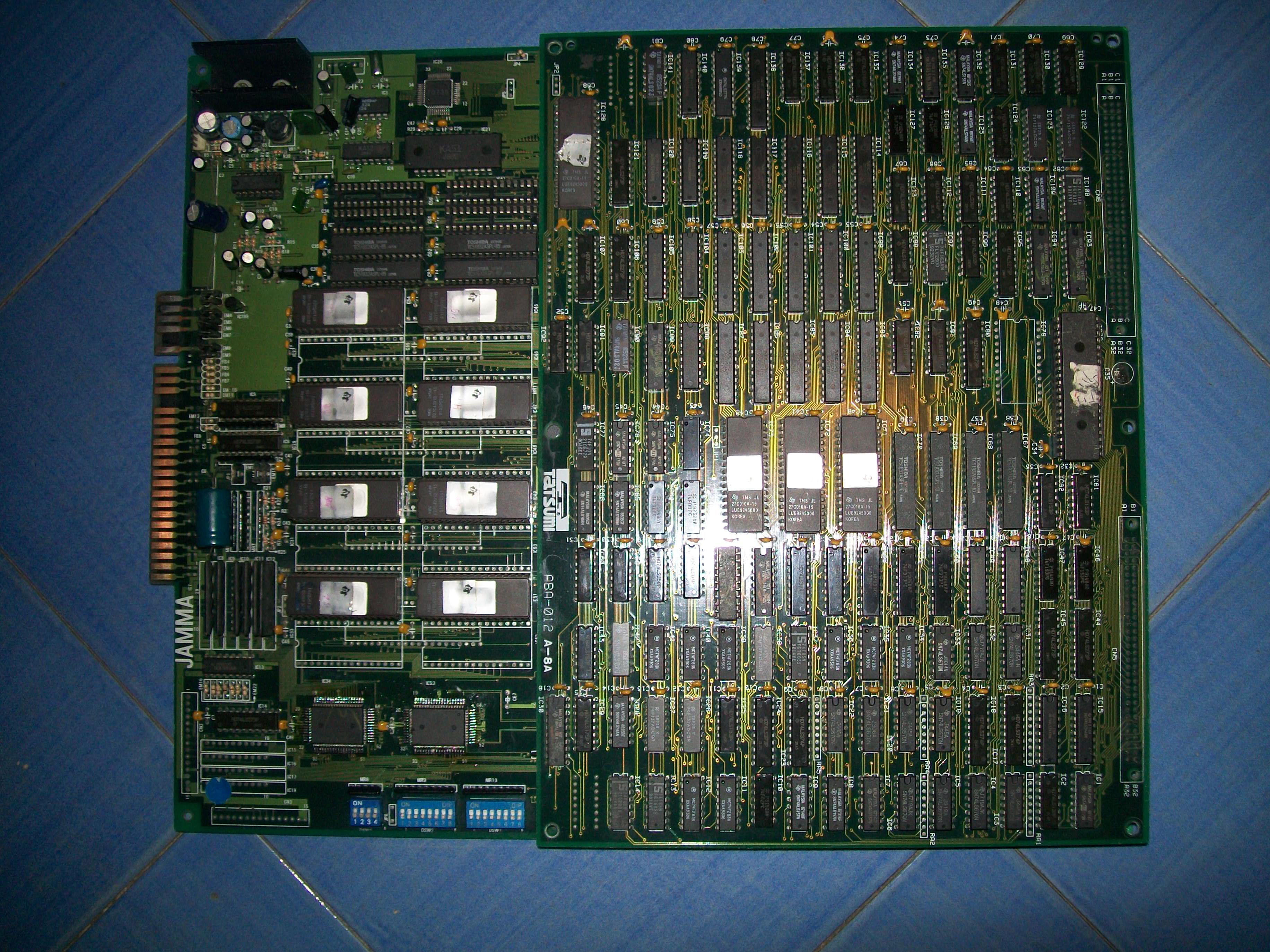
For the uninitiated game a beat ’em up which resembls Final Fight but it features also a versus mode.It was developed and published by the obscure Tatsumi manufacturer in 1992, it was one of their last arcade game before focusing on novelty sticker printing business.

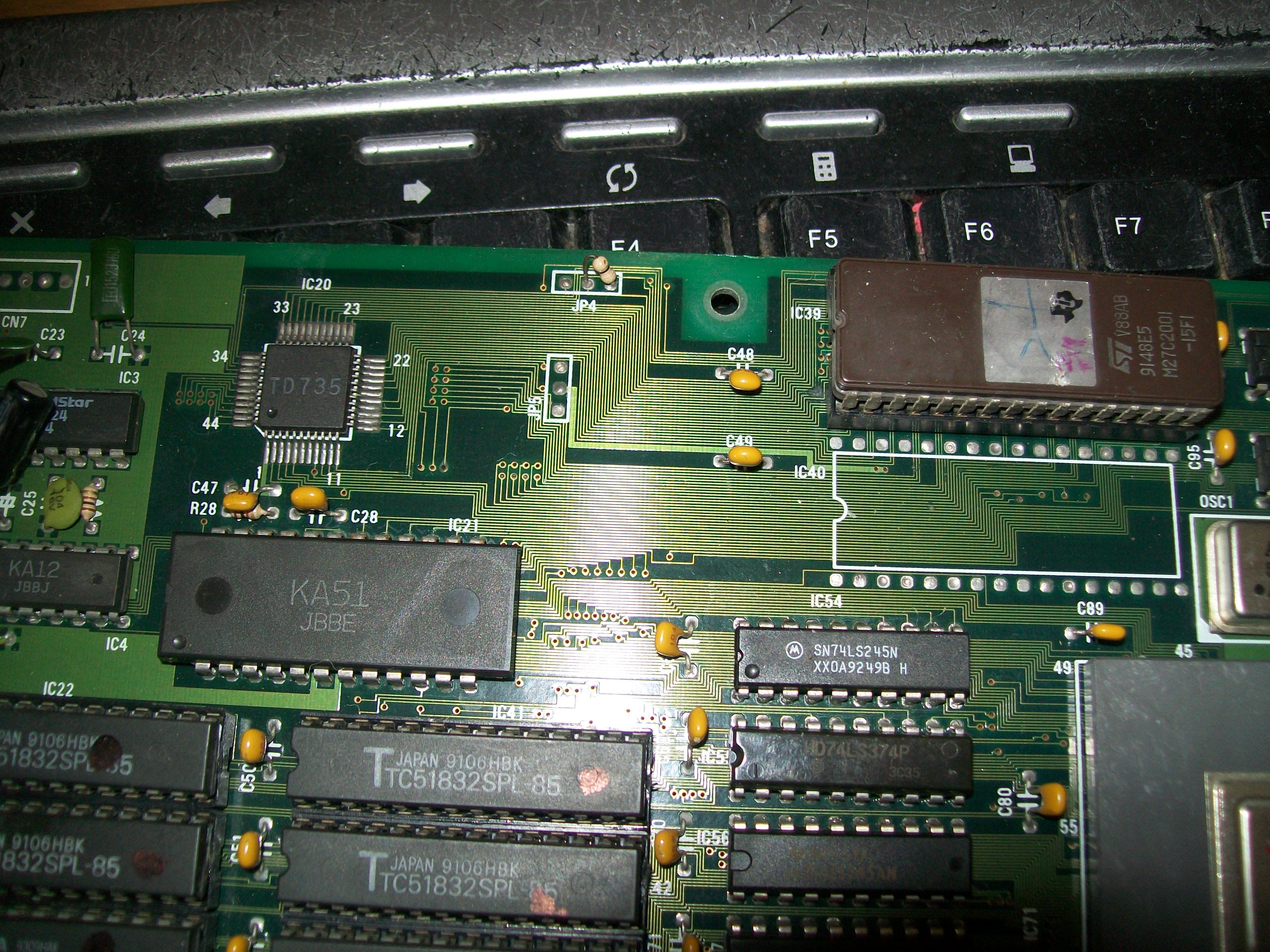
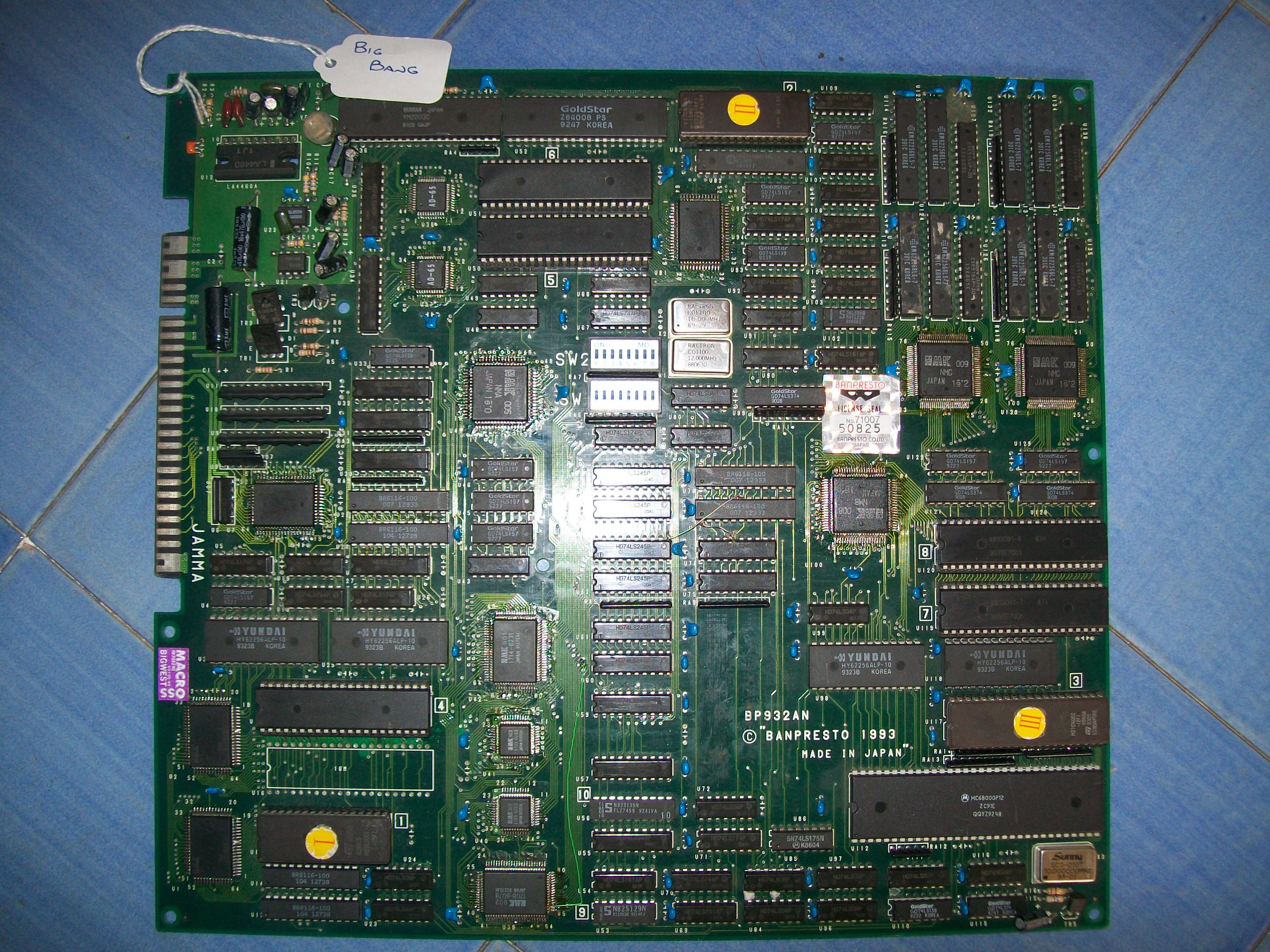
The board was completely dead, I got only a black screen.The hardware is complex : two 68000 CPU, a large PGA sprites custom IC, many PLDs, lots of RAMs.Here is picture with the daughterboard removed:

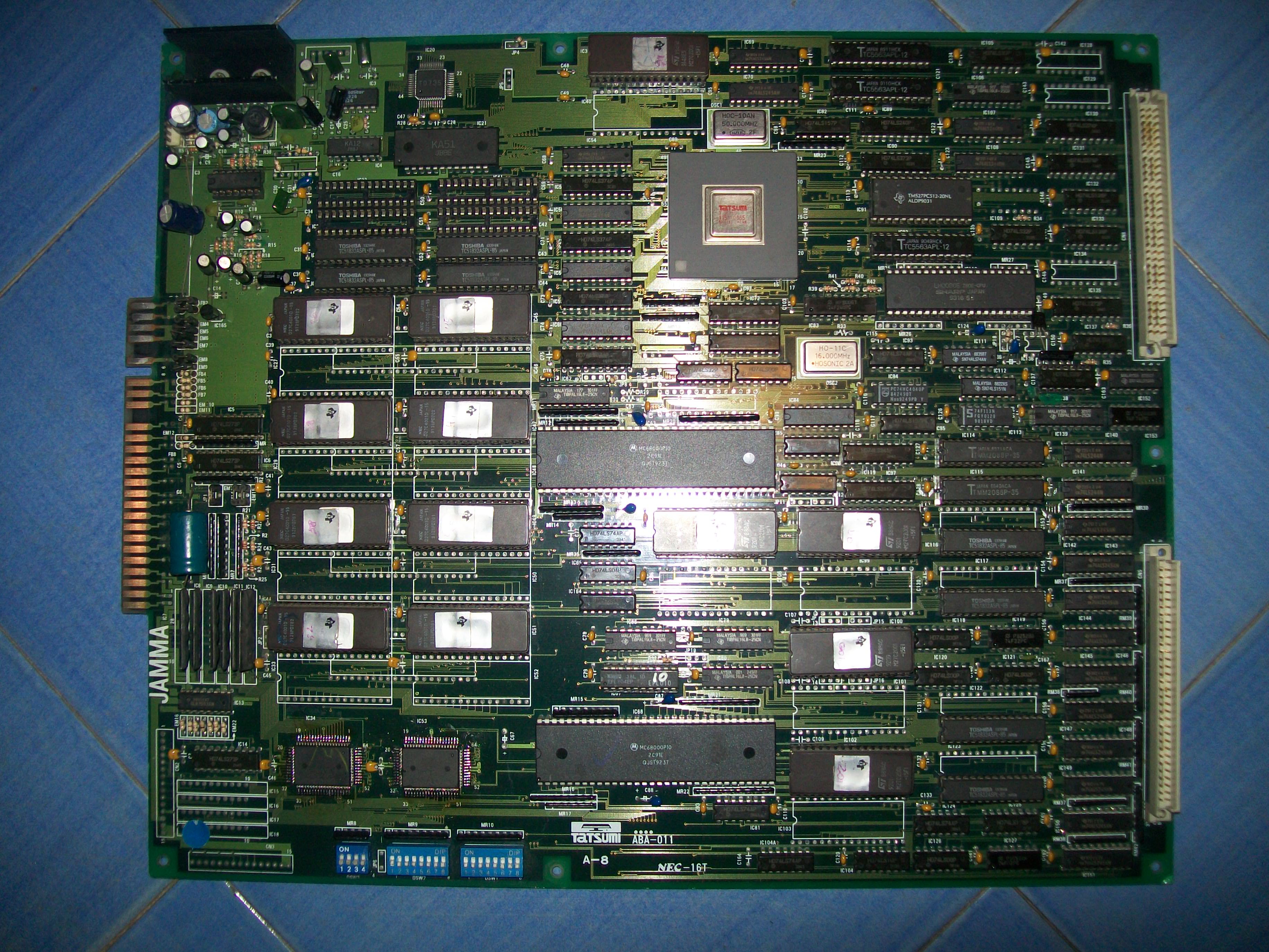
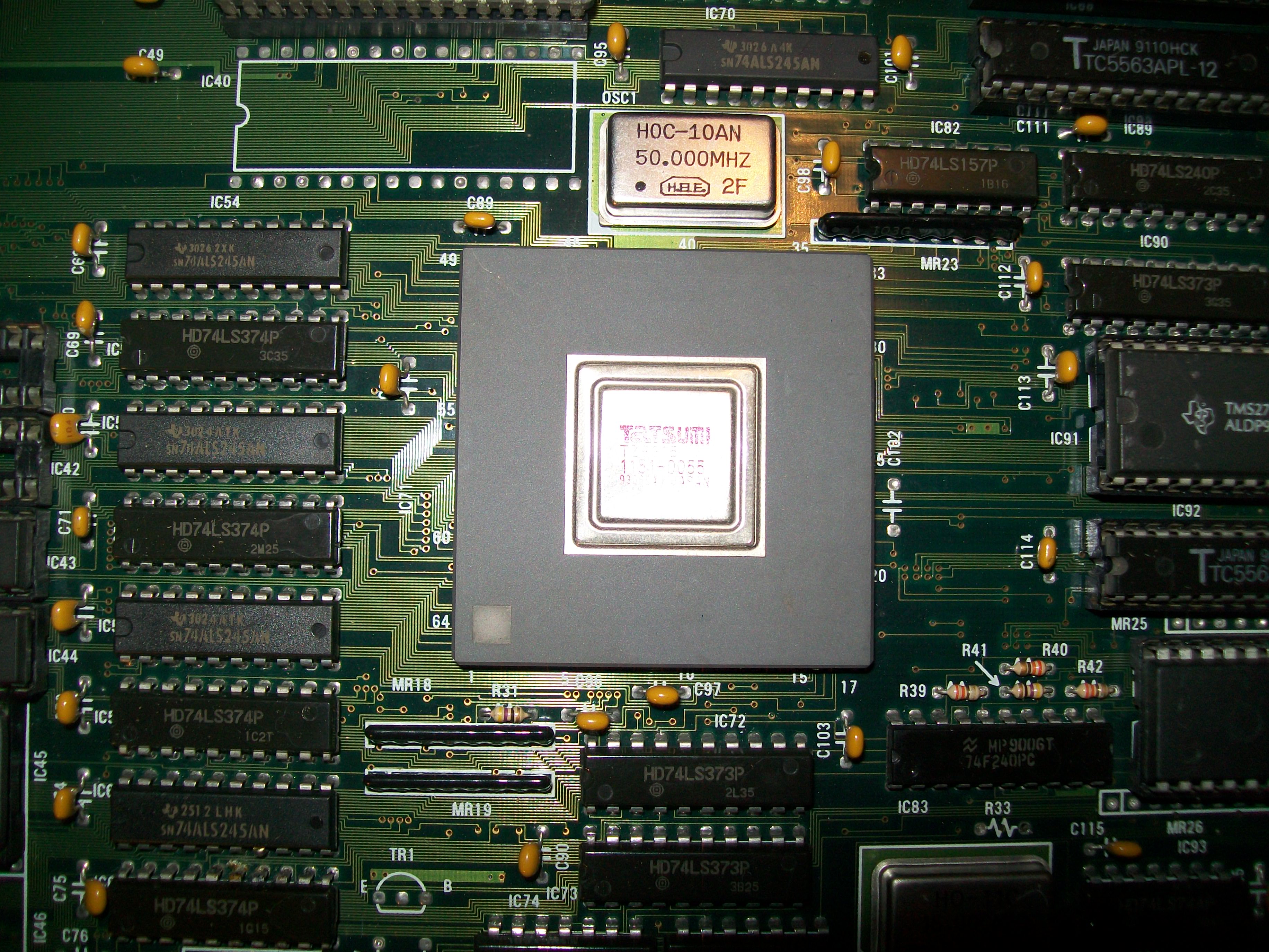
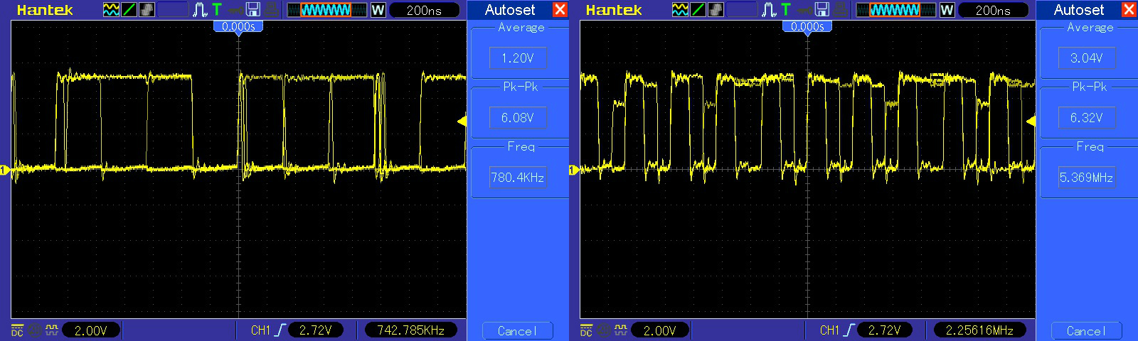
Probing the two 68000 revealed no clock, master clock is generated by a 50MHz oscillator and then divided by 4 in order to route a signal of 12MHz to both CPUs:

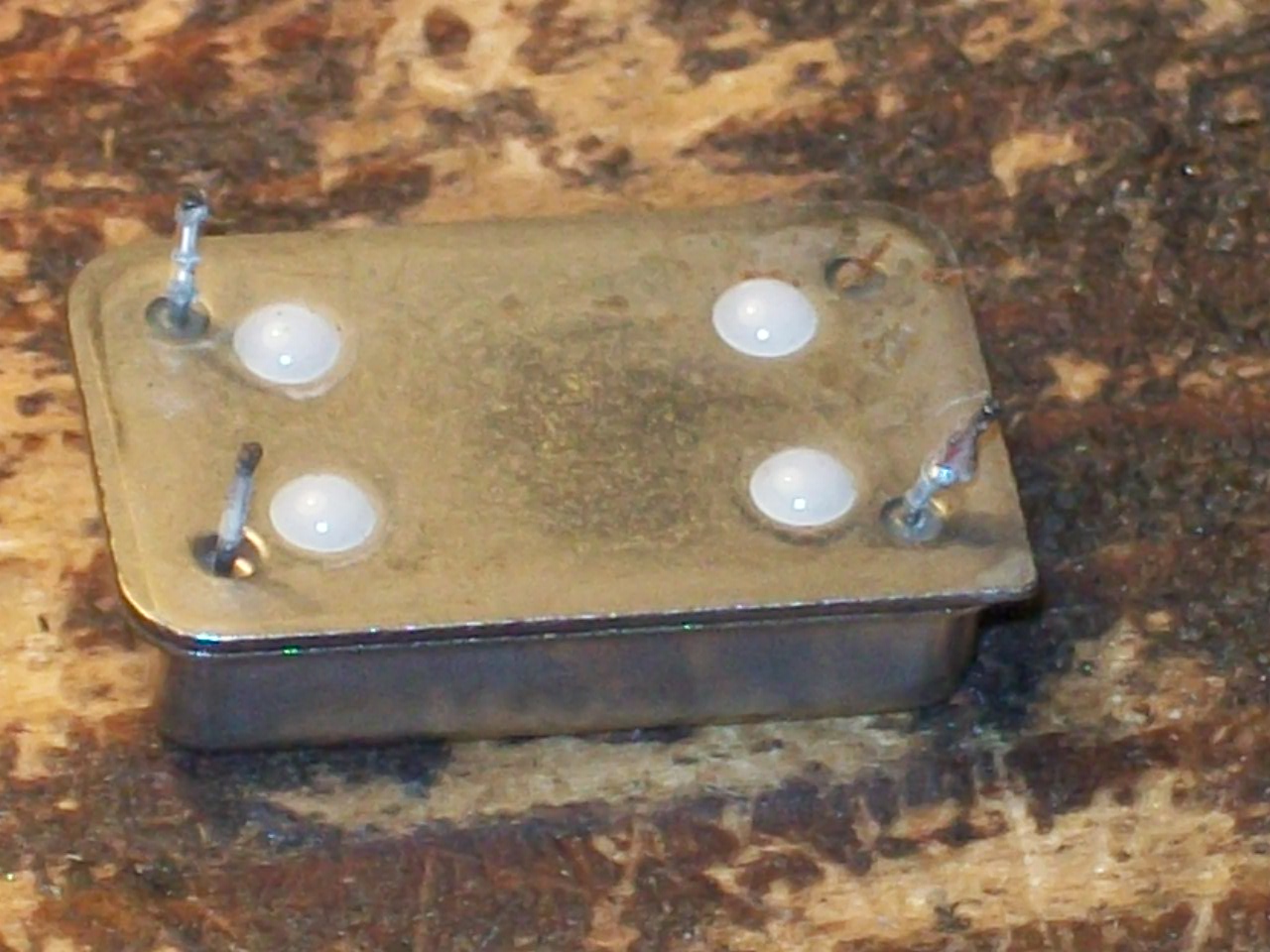
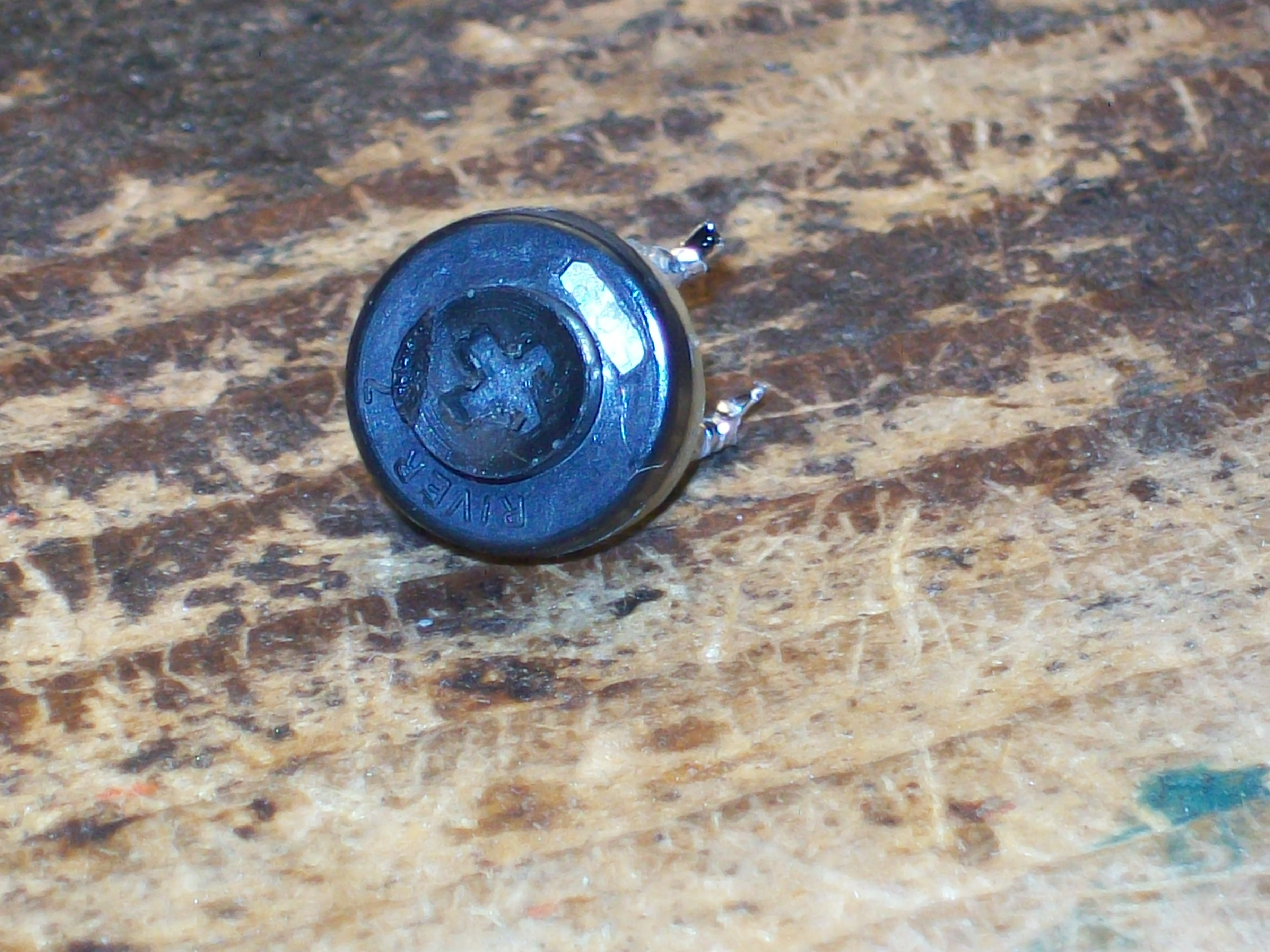
The output of the oscillator was dead, stuck at 1.64V  :

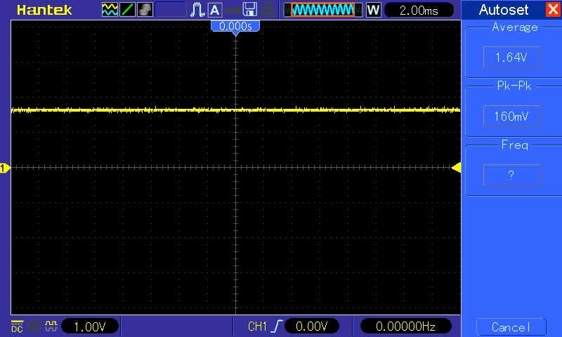
I removed it and the its VCC pin was stuck on PCB detached from the package due rust corrosion:

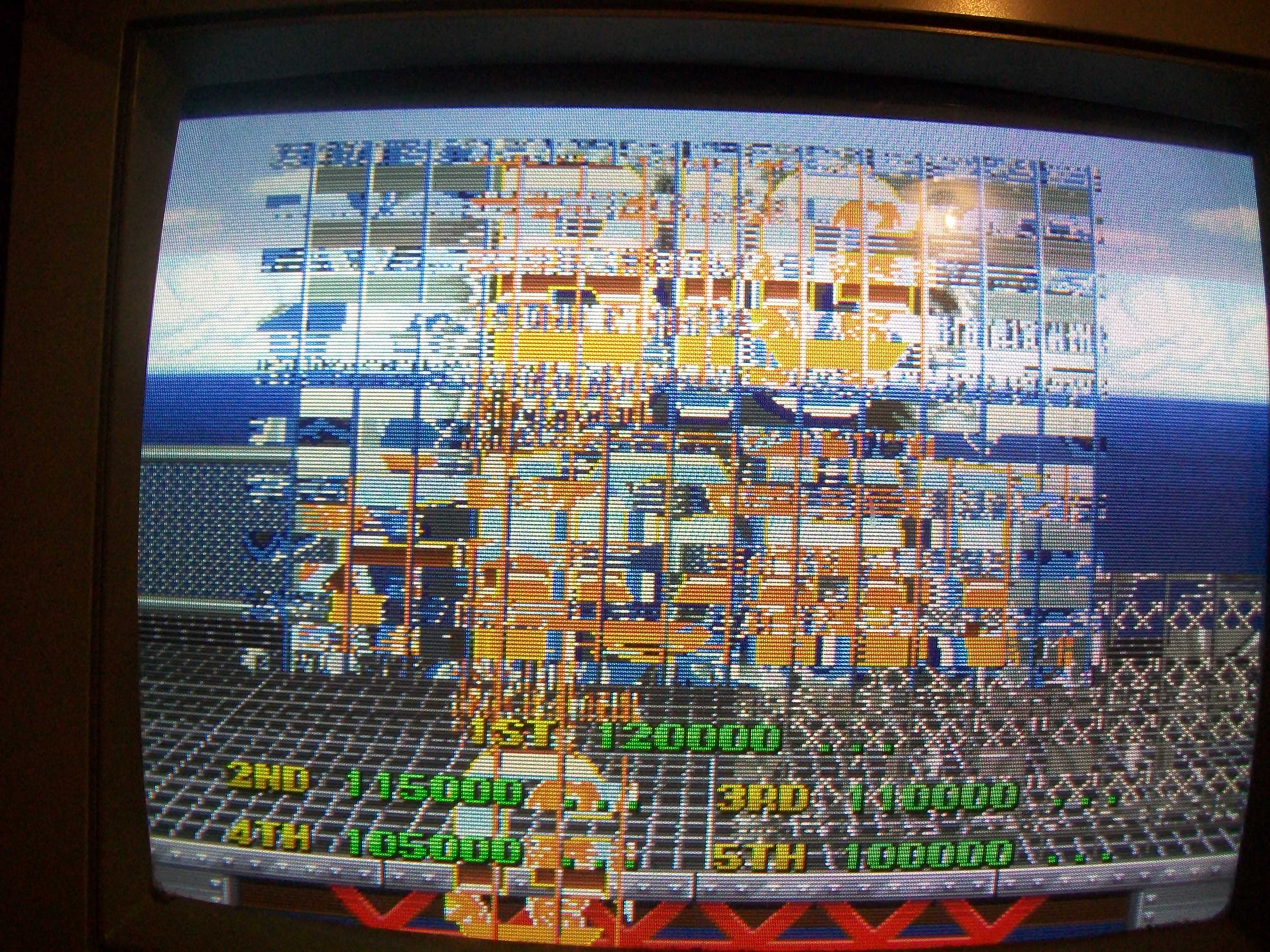
Fitted a good oscillator and board sprang to life although with bad graphics:

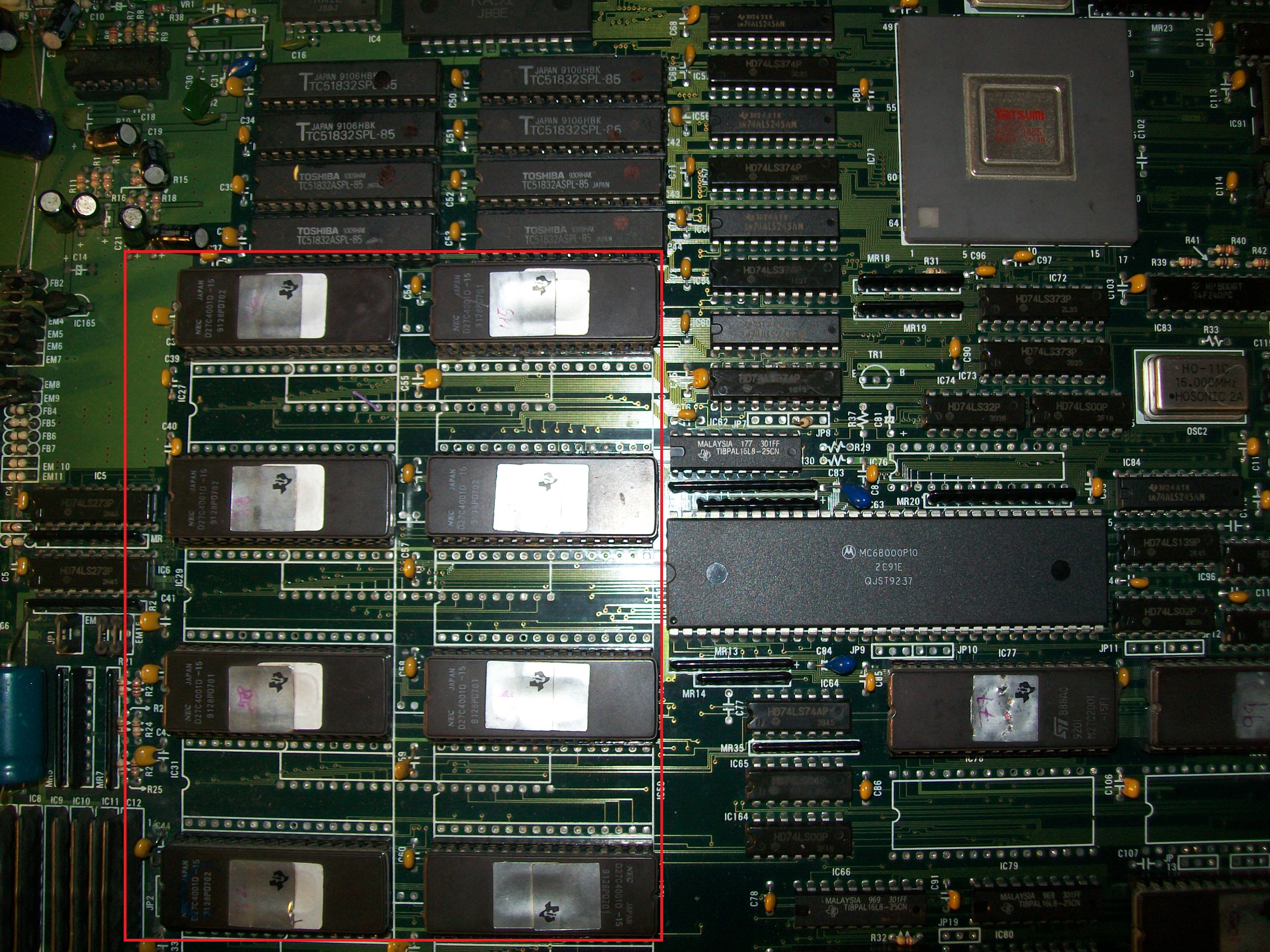
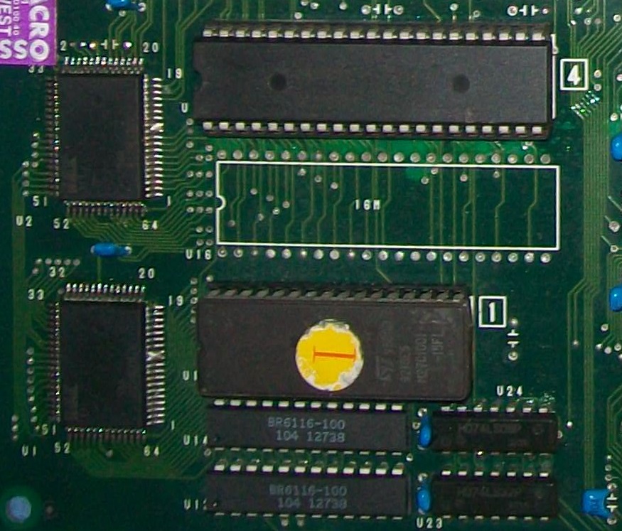
Doing a visual inspection I found four empy sockets, according to the MAME source PCB layout and pictures on the Net they had to accomodate four TC51832 32K x 8-bit pseudo-static RAMs besides the other four present:

Once fitted the four missing RAMs most of graphics were correctly displayed but sprites were absent :

The sprites are generated by the PGA custom ‘TZB315’ (see picture above) so I went to probe the surrounding area and found discrepancies between inputs and outputs of some 74ALS245 which are in the middle of ROMs and custom data bus:

I replaced them and, although they resulted good when tested out-of-circuit, I got sprites back although scrambled  :

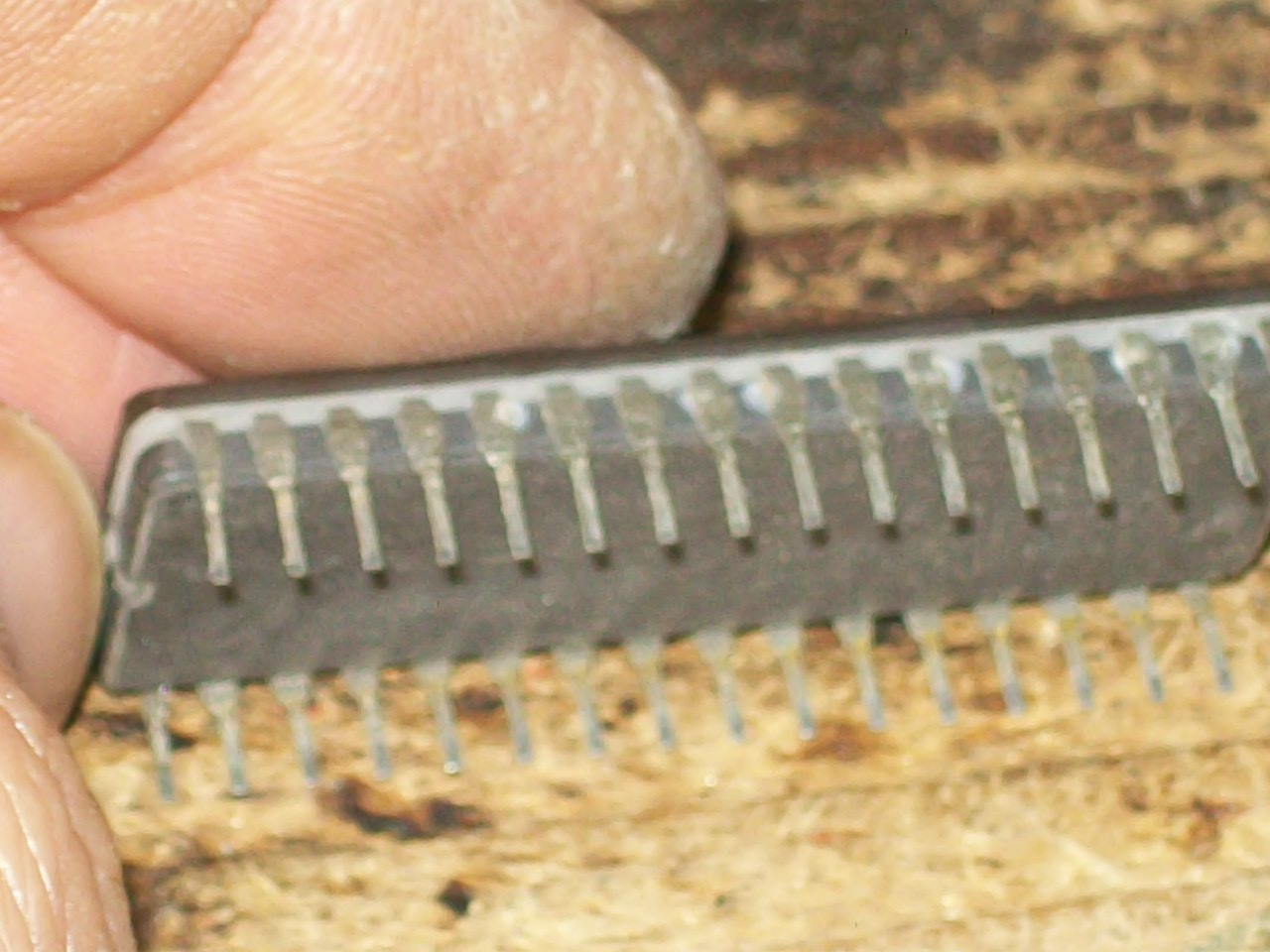
Sprites data are stored in eight 4Mbit 32 pin EPROMs:

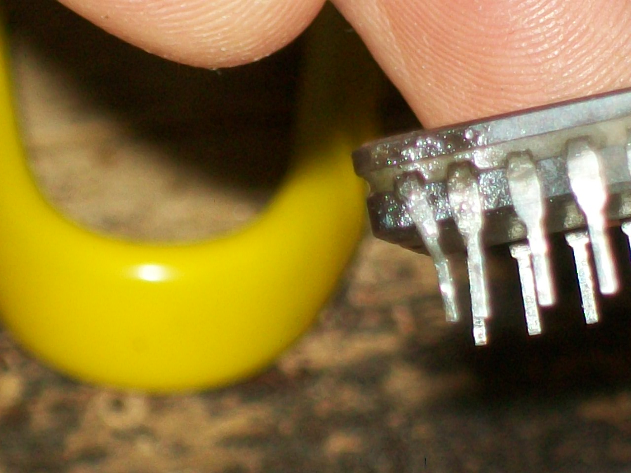
I dumped them and they matched the MAME ROM set but I noticed some of them had oxidized legs:

I cleaned them and at same time replaced a device with a dodgy pin:

This fully restored sprites:

But as you can see (or better, hear..) in the above video, sound was sometimes noisy and some voice samples were missing (like helicopter when you start a game or voice of special moves and enemies).

Here a recording from a working PCB for comparison:

The background noise was due a dirty 50KOhm potentiometer, I removed and sprayed it with a contact claner :

Voice data are stored in a 2Mbit EPROM and played by an OKI MSM6295 (corean rebadged one on this PCB)

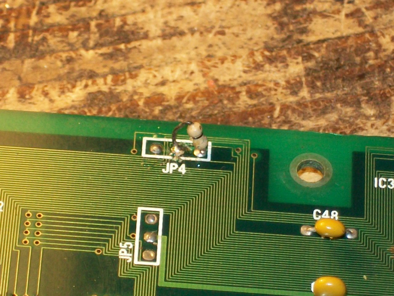
The dump of the EPROM was good, I also replaced the OKI with no luck.Probing the EPROM revealed that pin 30 (address line A17) was always LOW so the second half of the voice data could be not accessed.Doing a check with my multimeter revealed thas this pin was tied to pin 22 (/CE), this obvioulsy sounded me weird.Near the EPROM there was a jumper installed @JP4:

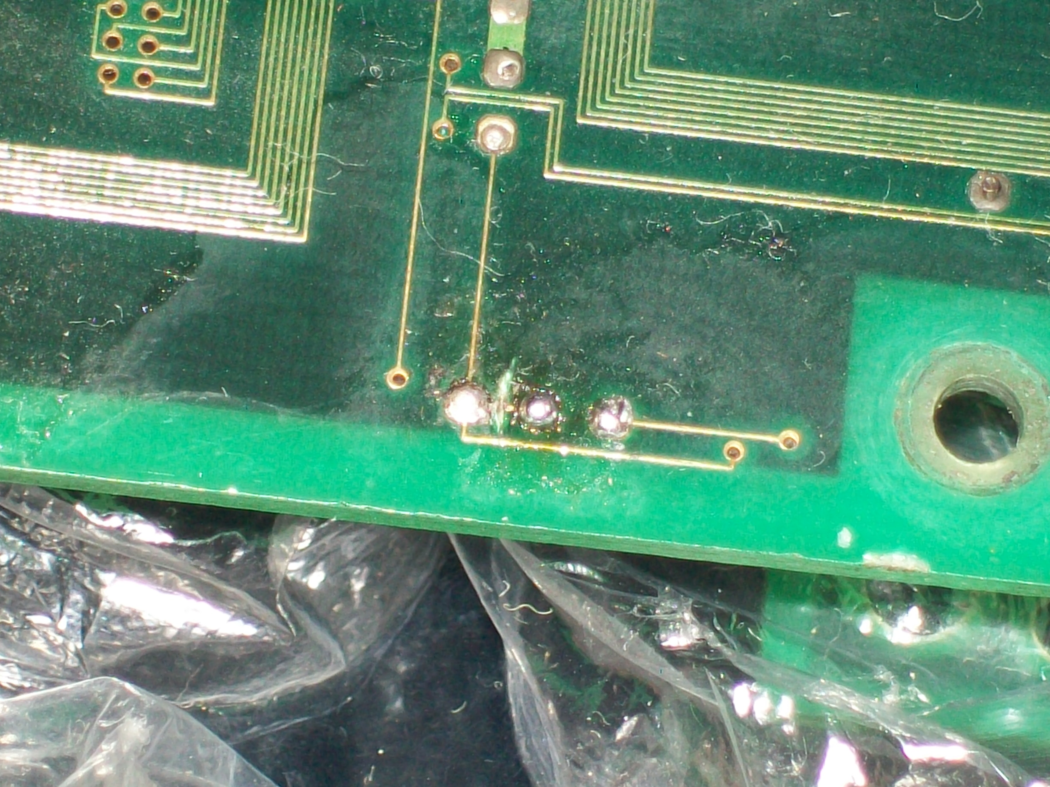
Looking at PCB pictures on the net I had confirm that the jumper had to be set in this configuration.But looking at its solderside I noticed a trace which connected  the central pad to the left one.This obviously, along with the jumper installed in that position, caused the short between the left and right pad resulting the two signals being tied together.So, I cutted this trace:

This restored the missing voice samples.No further issues were found so board 100% working.

 Posted by at 12:22 pm

GameKing multicart

 Projects  Comments Off on GameKing multicart
Mar 122017
 

I seemed to be one of the first to get the ball rolling with Gameking dumping.

I had to make my own part for the cartridge connector. This allowed me to make the breakout PCB.

This worked well enough for my dumping needs but I also wanted to test the dumps on a real Gamking. This led me to the first cartridge test. It has a bunch on things on that weren’t really needed but I was just playing about with ideas at this point.

It sort of worked but would do with some refinement.

This one worked much better but after dumping some 4in1 cartridges we found they didn’t always work properly using the homebrew cartridge. This led to the analyser PCB.

I never did get hold of any 4in1 carts myself so thats as far as that project actually got, although I don’t think its required anymore.

The final product is this cartridge. I believe one of these was used to aid in dumping the internal ROM.

It works fine for single games and a few 4in1 titles.

 Posted by at 1:03 pm
Mar 122017
 

This has been my main project for a long time now. Its something I started initially on the ABI Boardmaster 4000 as simple pin toggle routine. This allowed me to toggle the logic states of any pin and get a live update of the state of all the pins.
When I first got my Arduino MEGA I decided to port the program over to that as my first project.

PIN TOGGLER

It ran through a terminal window and was pretty much identical to the BM4K version I made.
It has a jumper on the board to switch power between 20 and 24 pin devices.

Revision 1

From this point I wanted to have a Windows GUI so I could have a graphical environment when using my ‘pin toggler’.

I also moved to using the ports of the Arduino to speed accessing up so with this in place I added the ability to brute force the operation of the chips so Caius could recreate 24 pin devices. The method used was identical to the way Charles MacDonald’s device worked so to keep compatibility with his analyser program. I don’t really require the ‘dumping’ feature of this as I use the hardware from Charles and its a lot faster to use but this option is there if I ever need it.
There were a couple of other things I wanted to add too from a hardware point of view. I added two reset buttons to the ‘shield’. One was to reset the Arduino itself and one was to reset the PAL/GAL in the socket. The jumper was still present on this revision to select 20 and 24 pin devices.

Revision 2

Not too long after revision 1 I decided I wanted to be able to control the power to the chip from the software. As you can see the jumper is gone and got replaced by a couple of transistors and resistors. Using this setup I could easily select 20 and 24 pin devices using software. I don’t think there were any other changes here.

Revision 3

This is where things started to gain momentum within the project. I spent a lot of time changing the software for this one.
So the hardware had a couple of obvious changes. First was I added LED’s to show which device type was being used.
Second was the socket itself. I had bought a ZIF socket for the project but it had 0.6″ spacing so in order to let me select between the two should I need to, I added both to the layout

The software got a big update this time around with many things being rewritten.
Myself and Caius had started to realise that there were quite a lot of PAL’s out there that used latches. Latches can be implemented in a non registered IC by using the feedback from an output pin. In some cases we haven’t even realised that latches were being used and it was only later we found out when people raised an issue.
To check for latches I added the ability to dump the PAL backwards so instead of counting the applied address up it counted down. It performed a forward and reverse operation then compared the results. If they were a match then it was a good bet that latches weren’t being used. I also added the option to use random addresses too which would give a more thorough test but took a lot longer to complete. I have never really needed to use this so far.

Revision 3a

This revision moved to surface mount components, removed the ability to use 0.3″ space ZIF socket and also added extra resistors. The resistors on the input only pins were there for protection in case of shorts.
Aesthetically, this one had rounded corners.

The software added support for those 20 pin devices that had an extra IO pin at pin 9 like the PLS153 and GAL18V10 although the supporting analyser software didnt support this so it never got used but it meant the pin toggle part of the software could use it.

Version 2

So here we have Version 2. All the previous iterations were what I called version 1. This one never turned out as I had hoped. I moved away from using ports on the Arduino which was a massive mistake. I did gain complete flexibility though. I had been studying some strange devices with a non standard IO configuration. This was going to be my of dealing with those devices. Unfortunately it became painfully clear that my software was so rigid that it didn’t allow changes to be easily made.
At this point I decided to rewrite my software from scratch opting for more of a suite environment for all this PLD rather than a simple bit of software.

The software as it stands right now is my proudest creation. It has GUI’s for MAME’s JEDutil and Charles’ analyser program and also the commandline version of WinCUPL too allowing everything to be done in the same place easily. It can also be set to automatically analyse a ‘dump’ and compile to a fusemap.

That’s where this project is right now. I’ve not finished with it yet but its not actively being developed either.
Hopefully I will get back to it at some point but at this moment there isn’t too much need

 Posted by at 12:45 pm

Big Bang – Power Shooting repair log

 PCB Repair Logs  Comments Off on Big Bang – Power Shooting repair log
Mar 102017
 

I had on the bench this Big Bang – Power Shooting PCB (also known as Thunder Dragon 2)

When powerd up it played almost blind, no graphics were displayed:

MAME source reports two devices containing the foreground and background tiles graphics data :

ROM_REGION( 0x020000, "fgtile", 0 )
ROM_LOAD( "1.bin",    0x000000, 0x020000, CRC(d488aafa) SHA1(4d05e7ca075b638dd90ae4c9f224817a8a3ae9f3) )    /* 8x8 tiles */

ROM_REGION( 0x200000, "bgtile", 0 )
ROM_LOAD( "ww930914.2", 0x000000, 0x200000, CRC(f968c65d) SHA1(fd6d21bba53f945b1597d7d0735bc62dd44d5498) )  /* 16x16 tiles */

My programmer warned me about a bad contact of pin 32 (VCC) when dumping the EPROM labeled ‘1’ U15 which store foreground data, most likely the +5V wire bond was detached from package:

:

Replacing the bad device with a programmed 1Mbit EPROM restored all graphics but some garbage were present on screen:

I promptly fixed this issue reflowing some of the surface mounted ASICs.At this point graphics were almost good except for some foreground objects which had wrong colors (bleeding too in some parts).Here is a comparison with MAME snapshot on the left:

and in details some of the affected objects (MAME snap always on the left):

At this point I spent some time to understand how hardware works but, honestly, due total lack of documentation, it  was a trial and error.I replaced some of the surface mounted customs until I caught the culprit :

Replacing it (spare part was taken from a dead Hacha Mecha Fighter PCB) restored correct graphics:

There is an explanation : this ‘NMK 903’ custom is connected to data bus of the 1Mbit EPROM containing the foreground GFX data which was faulty too.So most likely there was a chain failure hence one IC went bad and took out the other (not sure which one for first).But this few matters, another game successfully repaired!

 Posted by at 10:59 pm

Tube Panic PAL dump added

 PAL Updates  Comments Off on Tube Panic PAL dump added
Mar 082017
 

Today I dumped the only PAL from an original Tube Panic PCB (manufactured by Nichibutsu), device was a secured PAL10L8 @F17 on CPU board.Dump has been successfuly tested on GAL16V8 targeting device.Board was loaned by ‘robotype’, thanks to him.

 Posted by at 9:11 pm