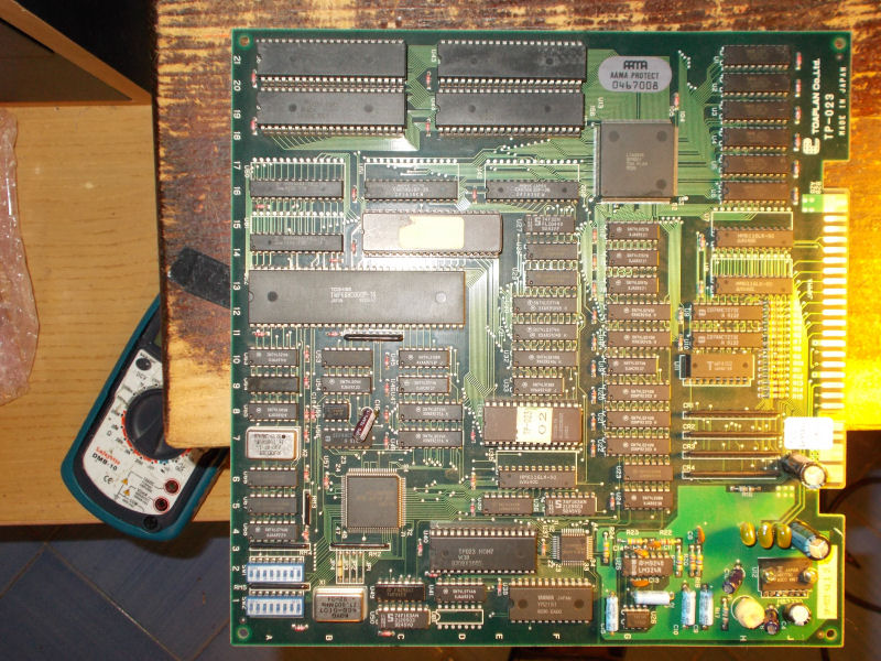
I got this Toaplan Knuckle Bash from my friend Josef for a repair.
He said board showed graphical issue which he could clear only by raising the 5V to +5.5V.After powered it up I had confirm of what he told me, actually colors were bleeding (you can notice it on right part of the picture below):
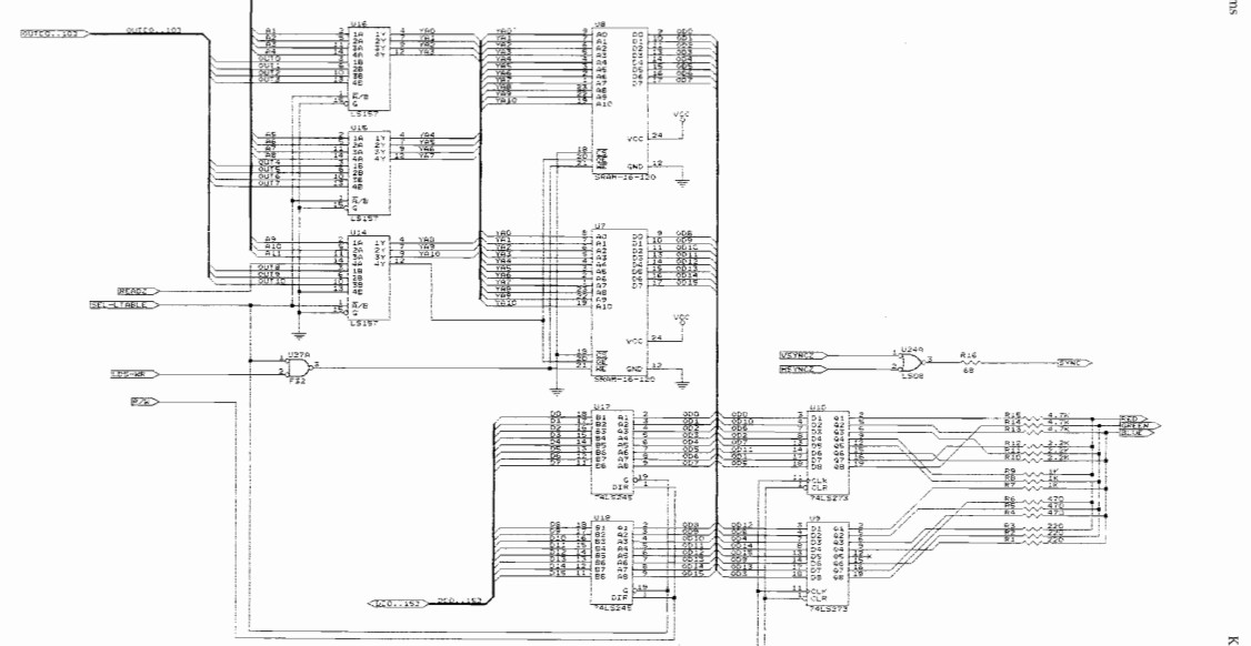
Schematics for this board were available so I could identify the part of circuit which generates the color palette:
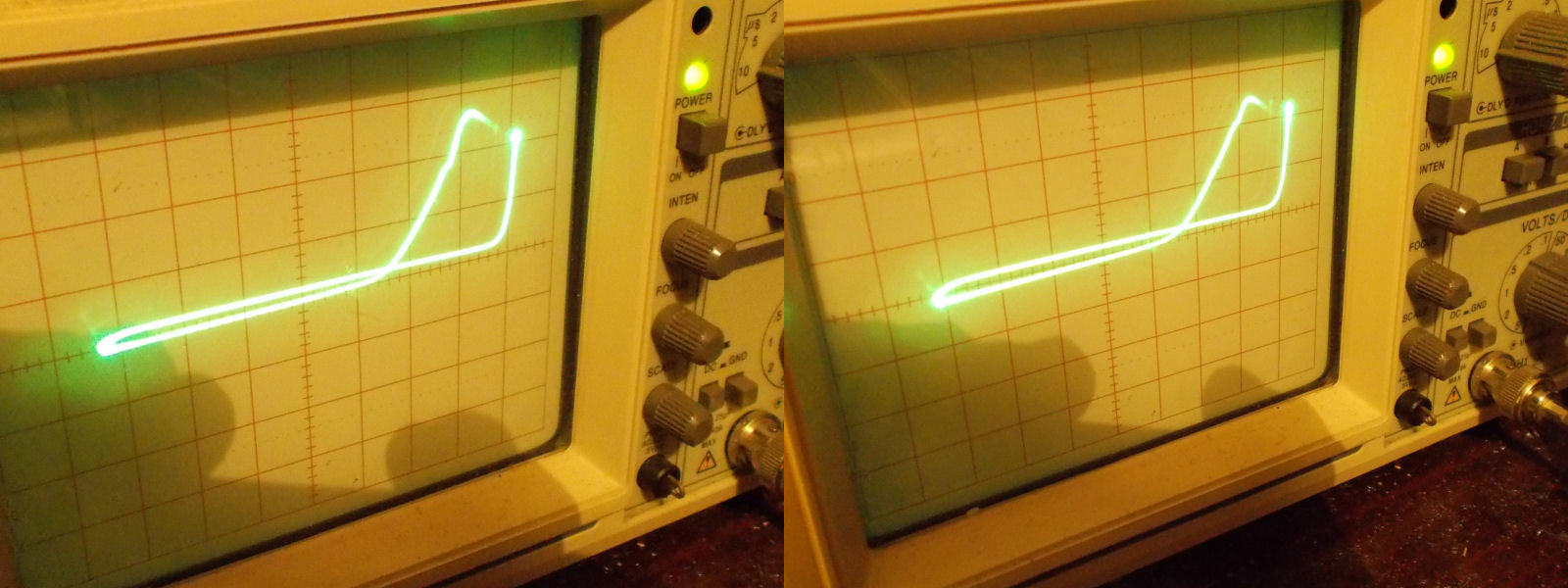
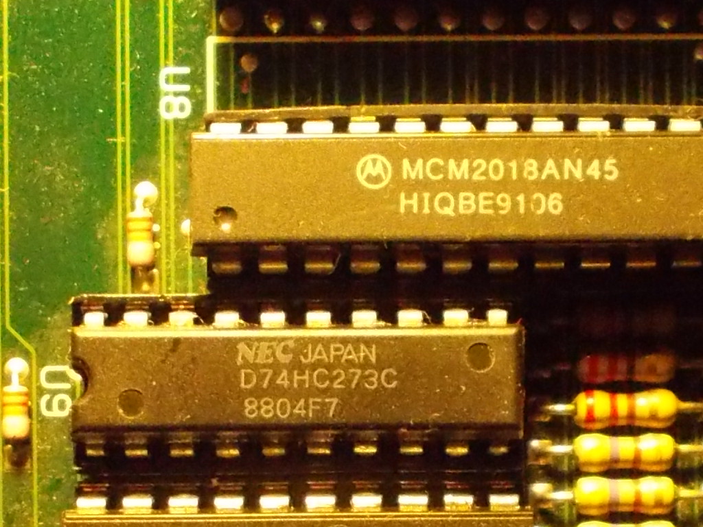
Data from the two 6116 SRAMs are latched by two 74LS273 (actually my board mounted two 74HCT273).When I went to piggyback the one @U9, colors were restored.I desoldered the IC but it succesfully passed the test in all my programmers, also comparing it with a good one on a tracer showed no abnormality:
Probably it was not really bad but its thresholds were altered.Despite this, I socketed and replaced it:
GeneralComments Off on Irem M84 partial schematics
Oct102015
I’ve started drawing out Irem’s M84 hardware. I’m using an R-Type II PCB so the ROM names are specific but the overall layout and functionality should be the same across the games.
I used the M81 schematics I made as the base as the hardware is very similar.
This will be updated as I get around to it or until I no longer need to carry on with it.
Available in the ‘Downloads/Schematics’ section.
I thought this repair was the perfect opportunity to show you how to correctly servicing the ‘infamous’ Konami ‘054986A’ custom audio module (obviously this is valid also for the ‘054544’ one).Follow this guide at your own risk.I’m not responsible for any kind of damage!
Let’s start.
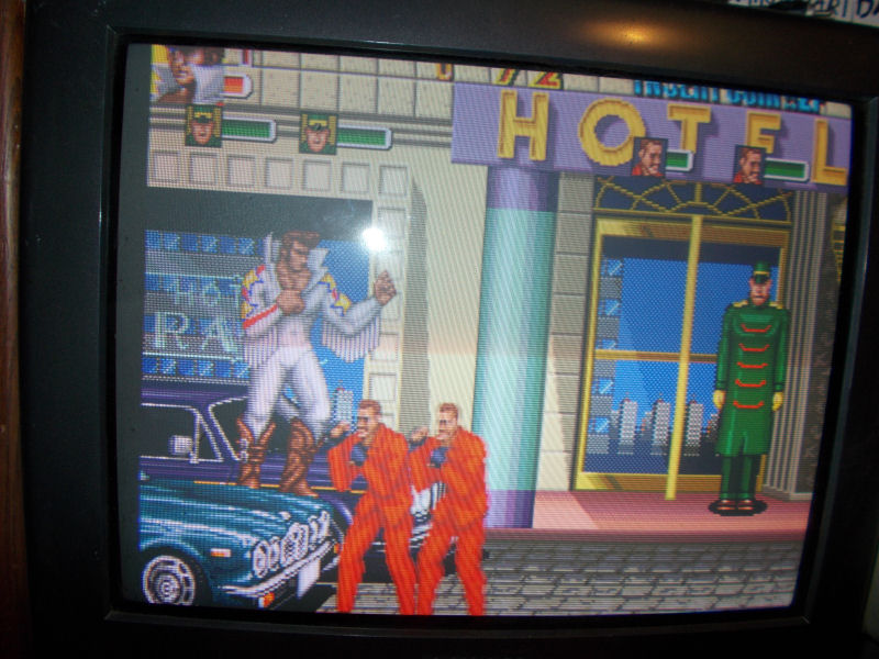
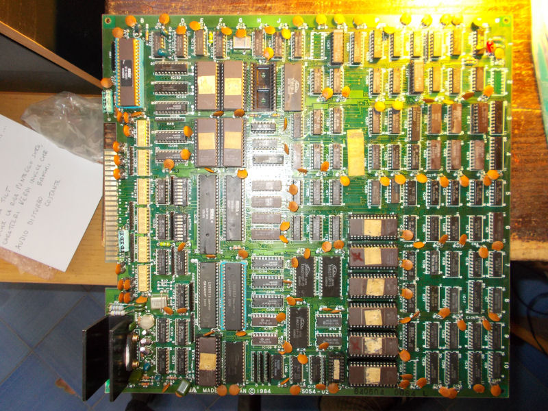
I got from my friend ‘supermik’ this Mystic Warriors PCB:
Board played fine but had an orrible sound output, very loud and distorted:
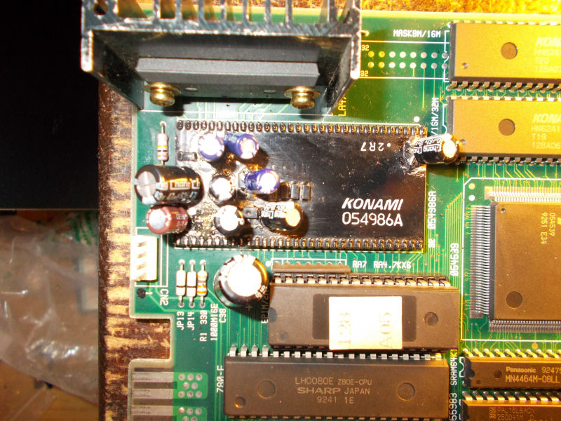
Obviously the culprit was the ‘054986A’ module whose capacitors were replaced by thru-hole electrolityc ones:
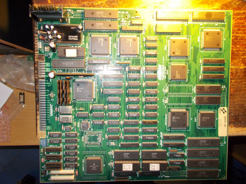
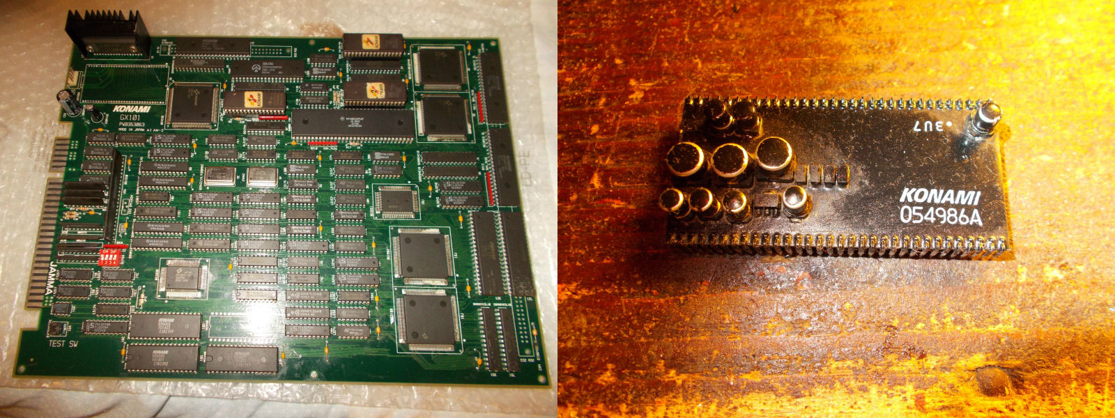
But this was not enough to fix the issue.So, instead of troubleshooting the module (the 4558 OP-AMP and the AD1868R DAC undersneath were most likely bad), I opted for its complete replacement using a Premiere Soccer as donor board :
The removal of a module consists in the following steps:
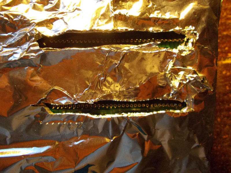
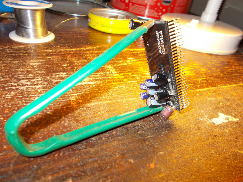
Prepare the board by covering the solderside with some aluminium foil leaving exposed only the pins of the module:
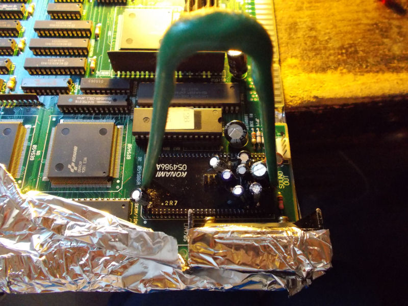
Clamp an IC extractor on the sides of module:
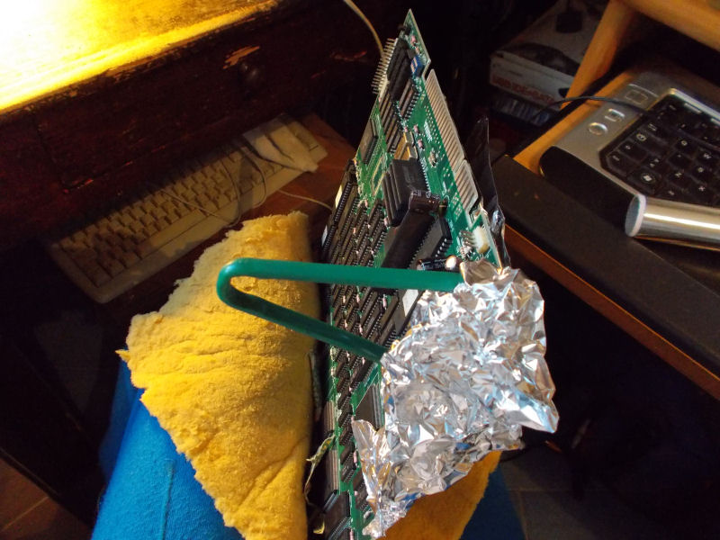
Put the board wrapped in a cloth or pillow between your legs:
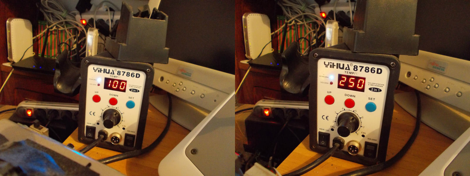
Now, with an hot air rework station do a first preheating of a couple of minutes on the exposed solderside setting the temperature at 100 Celsius degrees.Then, set the station at 250 degrees for a minute or less:
In both cases, you have to move the hot air gun back and forth without stopping otherwise you could damage the board.
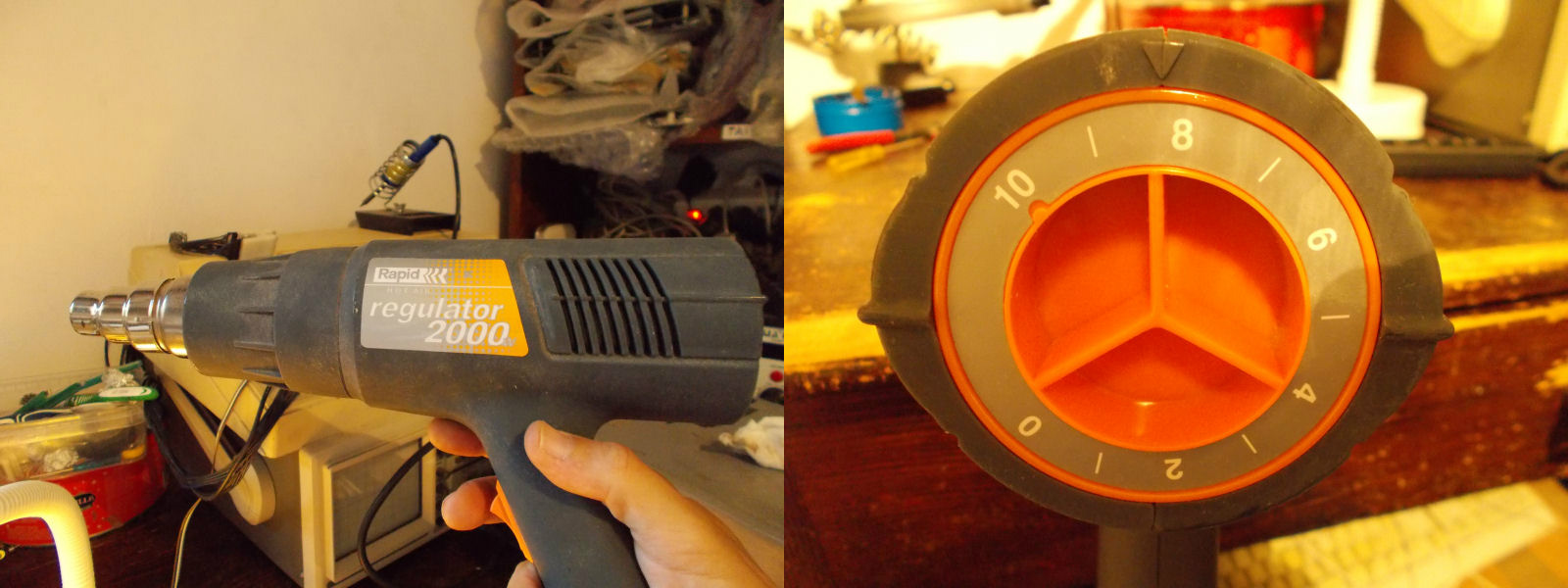
After done this preheating (needed to facilitate the solder melting and avoid heat stress) you have to use an heat gun for the last pass.Personally I use a 2000Watt model and set the temp to position ‘8’:
Keep moving the gun back and forth and at same time gently pull the IC extractor:
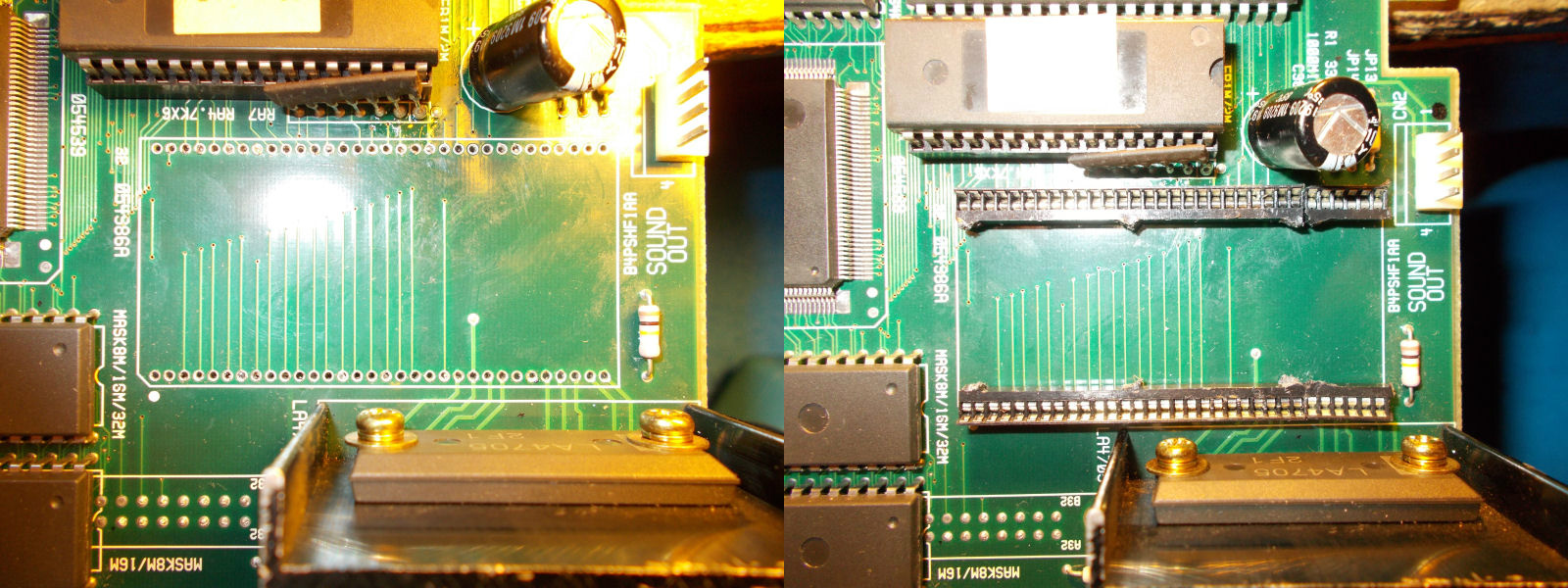
When the solder will arrive at the melting point, the module will come out easily from its seat:
Next step is the sockets installation, use 1.78mm pitch ones (cutting a single socket in half):
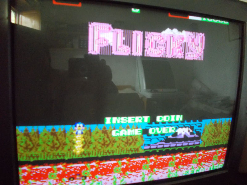
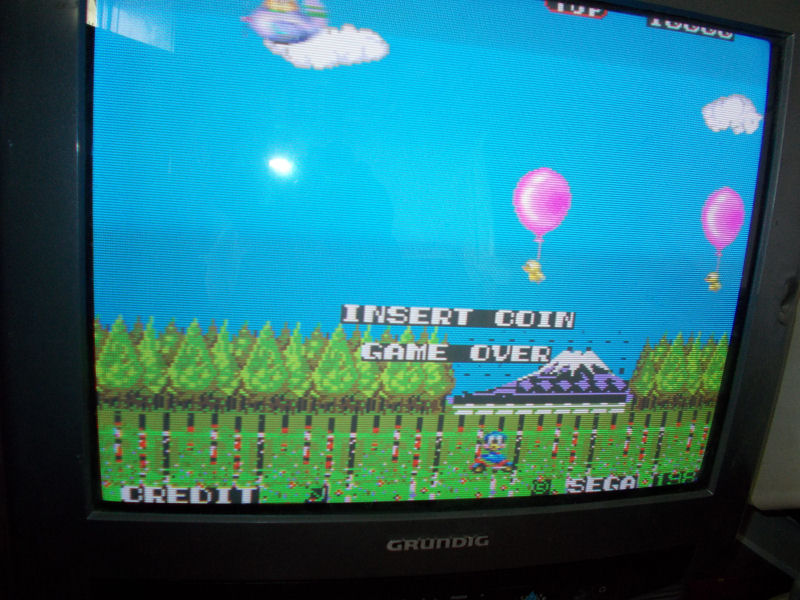
My friend ‘supermik’ sent me his Flicky PCB (released by Sega on System 8 hardware) for a repair:
When I powered it up,I got this scenario:
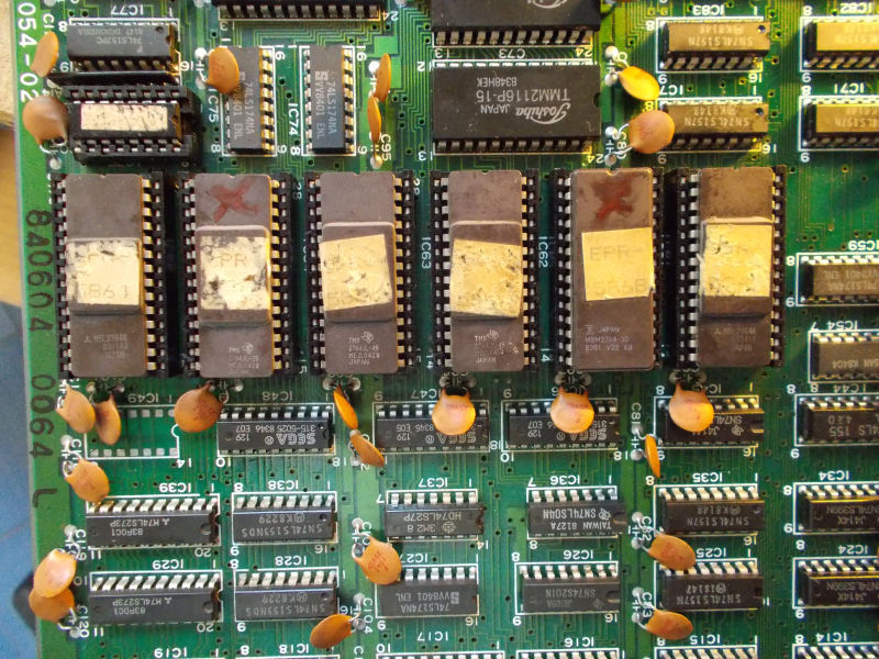
Sprites were fine but backgrounds were all wrong.Tiles data are stored in six 2764 EPROMs devices:
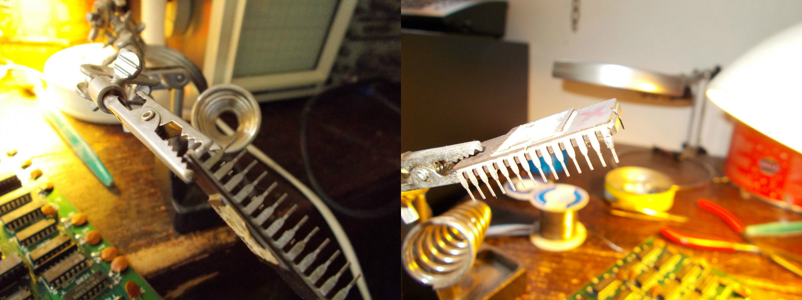
When I removed them for dumping, I noticed a broken pin on one device which I promptly rebuilt:
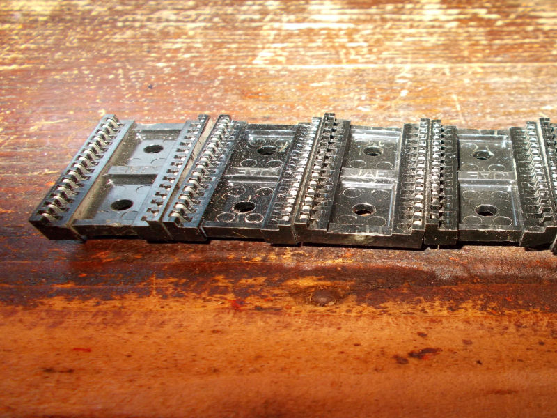
At same time I replaced four sockets of the tiles EPROMs (similar sockets are used also on Konami boards, they are beautiful but unreliable):
Backgrounds graphics were good now but still some glitches were present:
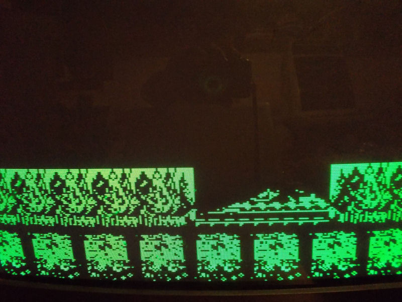
As I said, I dumped the six tiles EPROMs and they matched the MAME ROM set.But something still didn’t convince me so I used my video probe to check where the part of graphics affected was generated.For the uninitiated, the video probe is a small device that routes the green input from JAMMA to the video output allowing you to see on your monitor the signal captured with a probe.You can read more about here:
Today I dumped and successfully tested the PAL marked ‘DM620’ @2A from a USA version of Ghouls’n Ghosts (CPS1 hardware) .Until now we had only the MAME dump which anyway matches this new one.The other PAL present on PCB is marked ‘LWIO’ and it’s already dumped since it can be found also on Final Fight board.