Jun 242015
 

23/6/2015

In my previous repair I replaced a single capacitor to get the monitor working but this fix would prove to be temporary and only last a couple of months before something would go horribly wrong. The monitor is over 20 years old after all, so that was to be expected.

Several weeks ago I observed the monitor switch off for a split second and then back on, I thought this was strange but I knew something inside was on the way out. Since then strange lines would appear on the screen for a few minutes after power up.

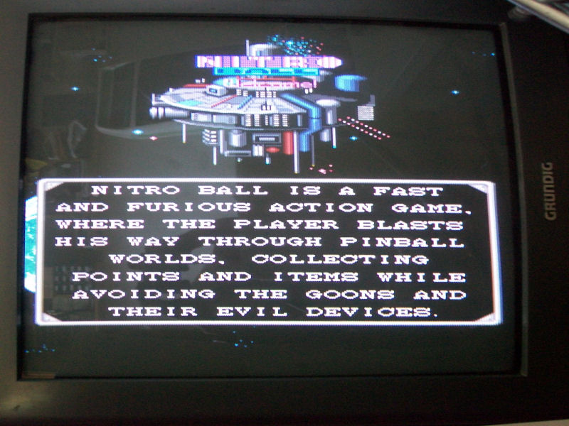
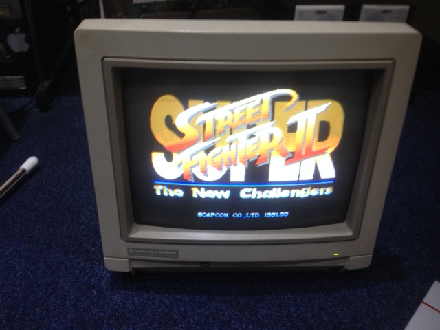
And more recently, I was in the middle of playing SSF2 when the monitor totally crapped out on me all of a sudden, the screen went blank and the power led went off. There also was a high pitched whine coming from the monitor which is common when the FBT dies in these monitors, or so I read on the various C= forums. When powered off the high pitched whine would gradually decrease in pitch until it was no longer audible.

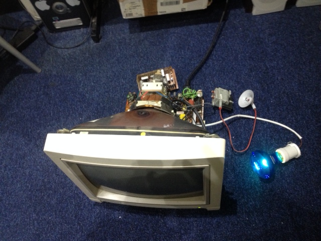
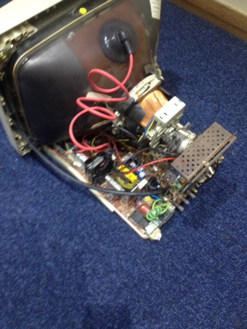
On to the repair. After opening the back of the monitor it was important to take the necessary precautions. All parts and tools were placed against the wall away from my work area ( the floor )  to create a safe working environment and prevent injury or damage to any components. I don’t have a large enough work bench so this was the best I could do with what I have.


IMG_0132

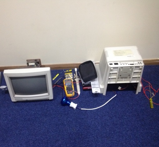
Tools used for this repair

  • flat head head screwdriver, automotive gauge wire & alligator clips ( used to discharge the CRT )
  • 240v 60w globe – series light bulb trick ( used to limit current ). 100w would have been better but I couldn’t find one.
  • DMM
  • Goot soldering station
  • Goot solder pump
  • 60% tin 40% lead solder
  • Plenty of coffee & biscuits were consumed in the process


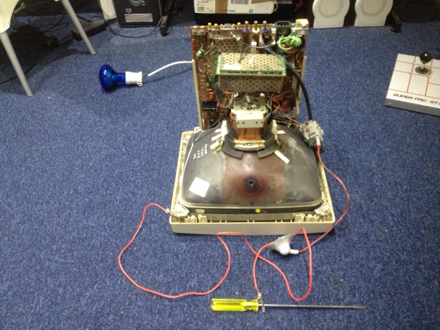
The next step was to discharge the CRT to avoid electric shock or worse. See my previous repair log for information on discharging CRTs. There is a link to a video by John’s Arcade which takes you through all the necessary steps to safely discharge it. Please do not do this if you are not confident or competent. You can get a nasty shock!

CRT discharged and anode suction cap removed from the tube. Discharging takes a fraction of a second with the screwdriver & attached wire from the screwdriver shaft to chassis ground of the monitor. Wait 10-15 minutes and repeat the discharging process to be safe or you can allow the flat-head screwdriver to maintain contact with the anode cap terminals and walk away for 15 minutes and do something else for awhile, like make a cup of tea or coffee.


Once discharged I then completely removed the FBT ( AT2079 37591 ) & the HOT ( horizontal output transistor – D1577 ). I also removed the neck board from neck tube which is required.

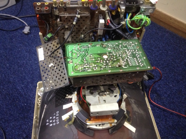
I wanted to test the power supply under some load. I soldered a 240v 60w lamp to the b+ ( to live ) and ground ( to neutral ) at the pads of where the FBT was installed. Pin 3 is b+ and pin 11 is ground.

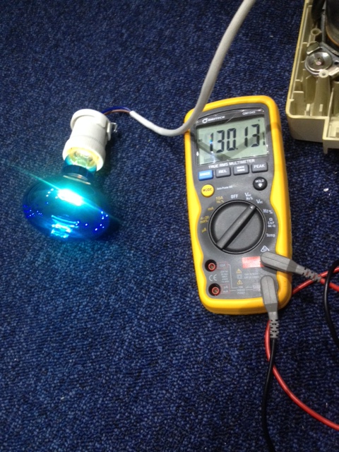
At least the power supply section looks good with the load. I measured 130vdc across the cap at 2451.

IMG_0140

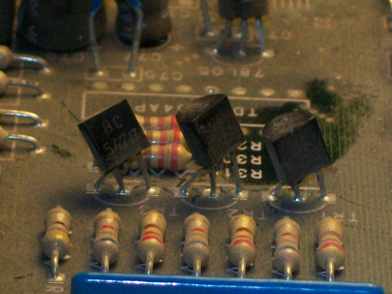
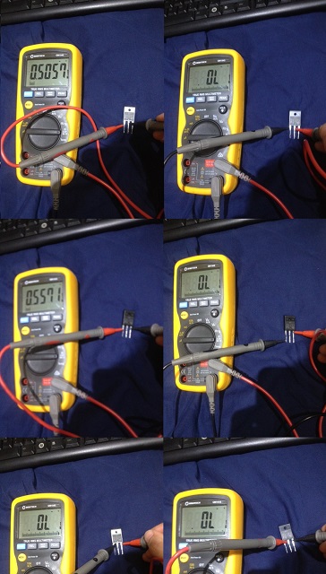
I decide to look at the HOT which can also fail and take out the FBT in the process.

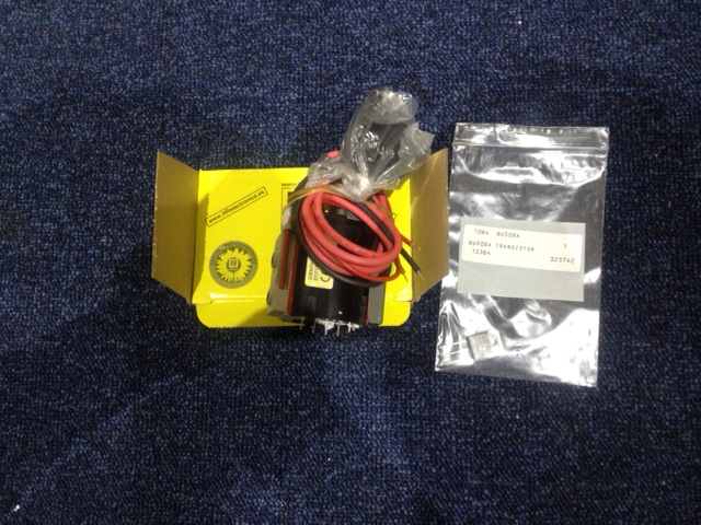
The D1577 HOT looks good to me but I have already ordered a spare just in case I need them. The BU508A is also suitable and was actually used in the same model. I ordered the BU508A

6

I’m confident the flyback is bad. I ordered a hr7533 ( which is a suitable replacement for the AT2079 37591 ). Since I am in Australia I found a supplier of the LOPT at Wagneronline instead of ordering from abroad which is handy for us Aussies if you happen to be one and are reading this. https://www.wagneronline.com.au/hr7533/9/ps/

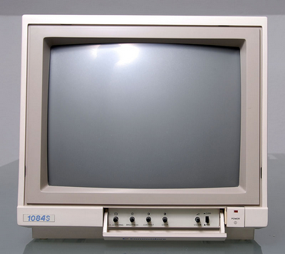
If you have the earlier version of the 1084 shown below with the on/off switch on the front ( 1084S-P ) then the replacement flyback is the hr7506 which Wagneronline stocks as well.

Commodore_1084S-P_small_ebay.de


24/6/2015

Wow that was fast shipping, 1 day from Sydney. So I really couldn’t wait to start working on the monitor this afternoon.

IMG_0151

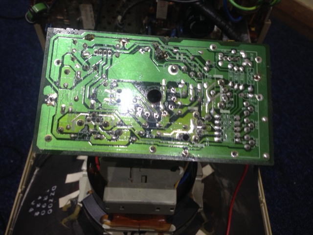
The next step was to remove the wires from the FBT to the neck board. To do this I had to de-solder and remove the RF shield first.

IMG_0152

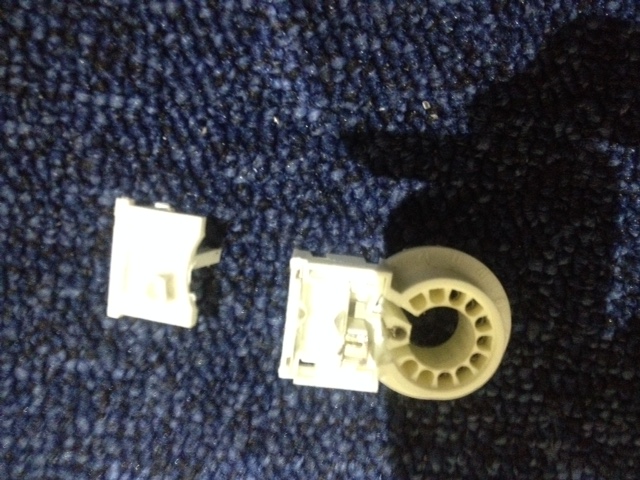
One of the wires from the old FBT to the neck socket snapped, so I had to remove the neck socket from the panel to remove the broken wire, no big deal 🙂

IMG_0153

The socket had to come apart to get the small piece of wire out. With patience I succeeded in getting the wire out without destroying the socket.

IMG_0154

After re-assembling the neck panel and soldering the two wires from the FBT to it, I soldered the 7 pins of the FBT to the main PCB. Then soldered in the new HOT and attached the clamp which holds the HOT in place so that it has good contact with the heat-sink, getting the HOT into that tight space was difficult and frustrating to say the least but I succeeded eventually.

IMG_0157

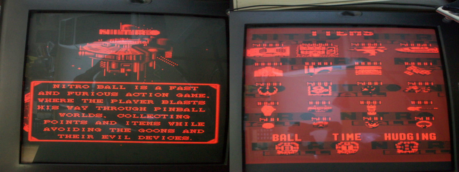
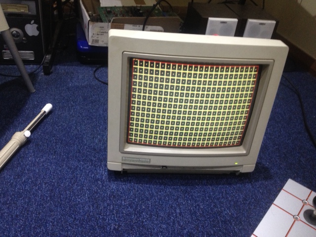
Moment of truth has arrived. I powered on the monitor with SSF2 running and was delighted to hear no high pitched whine sound however, the display was so bright that the CRT was blinking. I adjusted “screen” on the flyback until the blinking stopped and I could see faint text on the screen. I put the game into test mode and selected the dot hatch pattern and tweaked “focus” until I could get the display as sharp as possible. I then adjusted the “screen” to get the brightness where I wanted it & then finished off by tweaking “focus” once again.


IMG_0158

Happy with the results. The strange lines I described earlier are now gone and the display has never looked better. I re-assembled the monitor and I plan to play a few more rounds of SSF2 tonight.

IMG_0160

Thanks to caius for helping me with this repair.


Kyohkoh-Toppa (BreakThru) repair log

 PCB Repair Logs, Repair Logs  Comments Off on Kyohkoh-Toppa (BreakThru) repair log
Jun 232015
 

Maybe the name “Kyohkoh-Toppa” doesn’t say anything to most of arcade collectors/fans but if ,instead,I said “BreakThru” many of you will remember a game whose goal is to drive a dune buggy to “breakthru” the enemy lines of five different areas.So, for those who still have not understood, “Kyohkoh-Toppa” is the japanese version of BreakThru released  by Data East in February 1986 for the eastern market.

Here is the PCB:

Kyohkoh-Toppa_PCB

Board booted fine but it had a graphic issue since sprites were missing some lines:

sprite_issue

I noticed that problem went away if I flexed the board so there was some poor contact somewhere.In this kind of hardware all the graphics is generated in the bottom board so I reached it and found this:

2018_600MIL_adapted

Someone (certainly not manufacturer) replaced two TMM2018 300-MIL SRAMs with two 600-MIL equivalent ones adapting them in narrow sockets!For a better understanding of the package dimensions:

Not a neat job, for sure…Anyway, I could pinpoint sprites issue in the SRAM @11E (the one of the left picture) since problem was cleared when I pressed it.As you can see from picture they used some jumper wires on part side while patched some broken tracks on solder side :

broken_tracks_solderside

So, I decided to remove this hack, check that all the RAM connections were fine and use a proper 300-MIL chip in a new socket :

socket_job

In this way sprites were stably restored and board 100% fixed.

sprites_restored

 Posted by at 11:12 pm

Nova 2001 repair log #2

 PCB Repair Logs, Repair Logs  Comments Off on Nova 2001 repair log #2
Jun 232015
 

Another Nova 2001 repair log here after the one from Corrado.Here is the “patient” on the operating table today:

Nova_2001_PCB

PCB was sent me flagged as “SOUND ERROR”, indeed when I fired it up, the music and sound FXs were only noises.Here is a record for a better understanding of what I mean:

All sound/FXs are generated by two AY-3-8910 chips so I went to probe them  and found no activity on all their pins.This was due a missing clock on PIN22 of both (signal is shared) as shown on analog scope:

missing_clock_PIN22

I could trace the CLOCK signal back to PIN9 of a 7474 @3E and comparing the chip with a good reference one using with my HP10529A confirmed trouble on this output:

7474@E3_comparing

It failed miserably when tested out-of-circuit:

7474@3E_failed

Mission accomplished, another arcade PCB preserved!


 Posted by at 8:51 pm

The Battle-Road repair log

 PCB Repair Logs, Repair Logs  Comments Off on The Battle-Road repair log
Jun 232015
 

Got from a friend this The Battle-Road PCB :

The_Battle-Road_PCB

Honestly I never heard of this game before.Anyway, it runs on IREM M62 hardware which is the same one of Kung-Fu Master and other games.

My friend said that sprites was completely missing and he was right but comparing what I got with MAME emulation  also text/characters colors was incorrect :

texts_sprites_issue

MAME_comparison

So time to investigate and start to study the sprites circuitry which is located on bottom board.Data from the six sprite ROMs are multiplexed by a custom maked “NANAO KNA6034201”, its outputs go to some TTLs (74LS157 and 74LS374) until they hit the RAMs I/O pins (four 2149 DRAMs) which were all stuck HIGH.Probing the custom revealed it did its job, all outputs were correctly toggling as well as piggybacking the four DRAMs didn’t change anything so fault was in the middle.When I probed the 74LS157 @H3 with my HP10529A logic comparator I got this:

74LS157@H3_comparing

So troubles on all its outputs that were confirmed from my logic proble which reported them as stuck HIGH.Obviously IC failed when tested out-of-circuit:

74LS157@H3_failed

Fitted a new 74LS157 restored sprites but as I said early text/character colors were wrong compared to MAME emulation correct ones.Text colors BPROM was dumped fine so I went to dump the two ROMs containing this part of graphics and I found they were swapped into their respective sockets (on the left the wrong positioning, on the right the correct one) :

characters_ROMs

This fixed board completely.End of job.

board_fixed

 Posted by at 10:04 am

Nitro Ball repair log

 PCB Repair Logs, Repair Logs  Comments Off on Nitro Ball repair log
Jun 212015
 

Got this Nitro Ball PCB from my friend Corrado as not working:

Nitro_Ball_PCB_

When I first fired it up I was greeted by a solid black screen.Hardware uses, like other DATA EAST games, a custom 68000 CPU in QFP package marked “59” whose pinout is unkown since no schematics are available and  nobody has yet figured it out.My first intention was to probe the RESET line on main CPU, this is the first thing I usually do when I got a totally dead board (along with CLOCK pin) but since I couldn’t I started with my visual inspection and I found this:

4.6uF_50V_lifted_pin

A 4.7uF 50V capacitor @C43 with anode terminal desoldered from its pad.This may seem a minor thing a but not in this case since this capacitor was part of the RESET circuitry along with a voltage monitor transistor (silkscreening suggests a  PST518A IC but a generic BC547 transistor was used instead in order to detect a voltage and generate a RESET signal) :

RESET_circuitry

Once replaced this capacitor board properly booted but all screen was red:

red_screen

A dominant red color means that blue and green ones were missing so I traced them back to three transistors:

BC547_colors_transistors

As you can see from picture above manifacturer/assembler used three compatible BC547 transistors compared to original silkscreened part adapting their different pinout by rotating them and twisting the base and collector legs.This caused a short circuit between the base and collector of the blue and green (TR2 and TR3 on picture) transistor.After clearing the short colors came back to normality.

colors_restored

No  further issues were found on PCB so I could declare this one 100% fixed.


 Posted by at 8:29 am