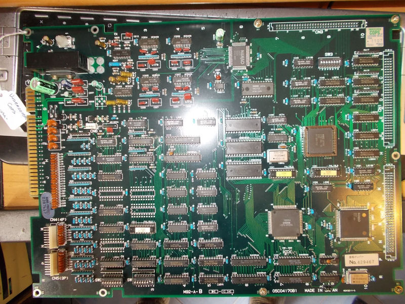
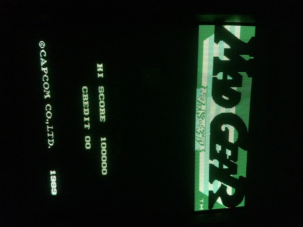
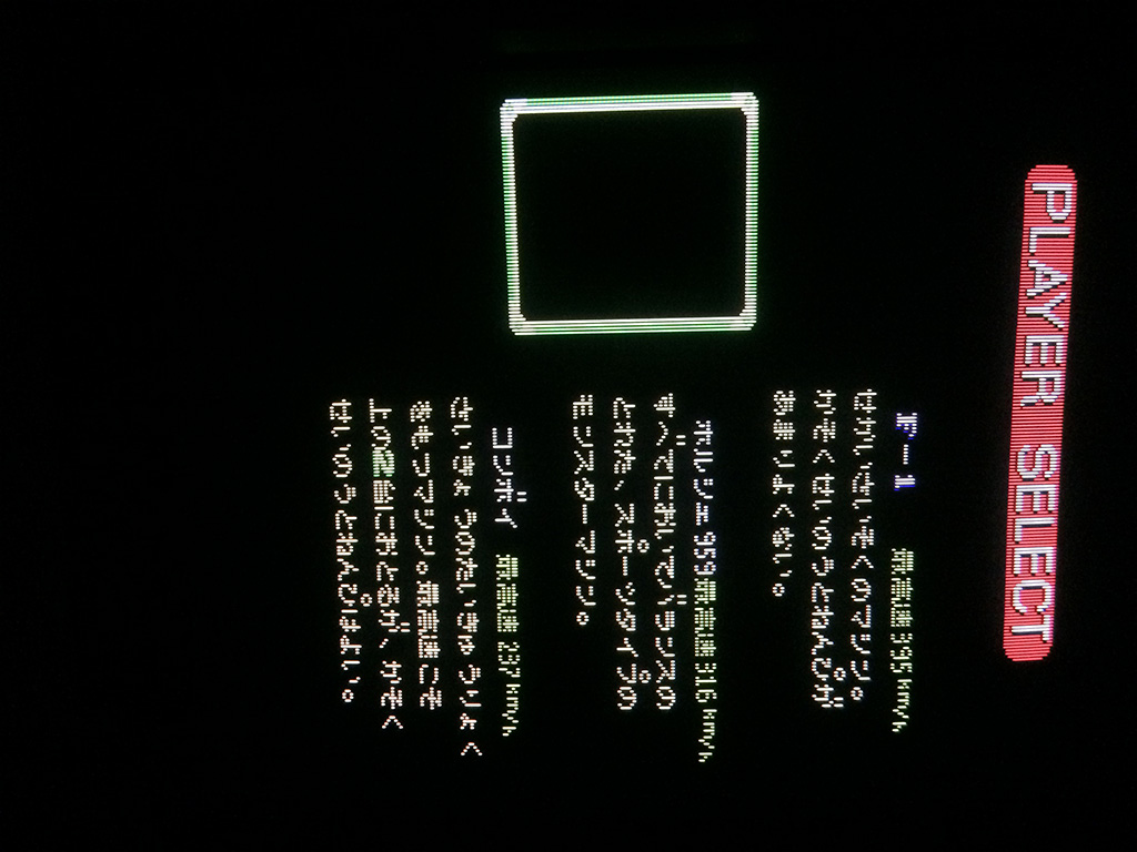
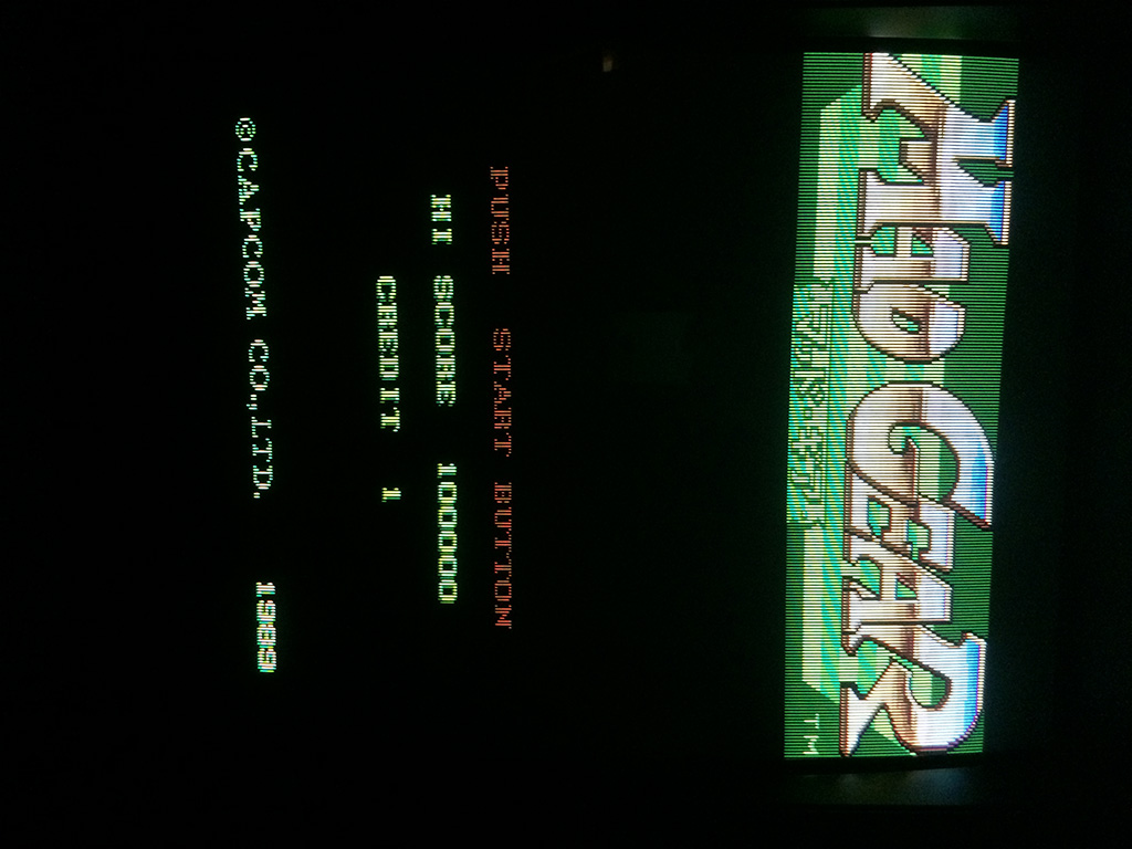
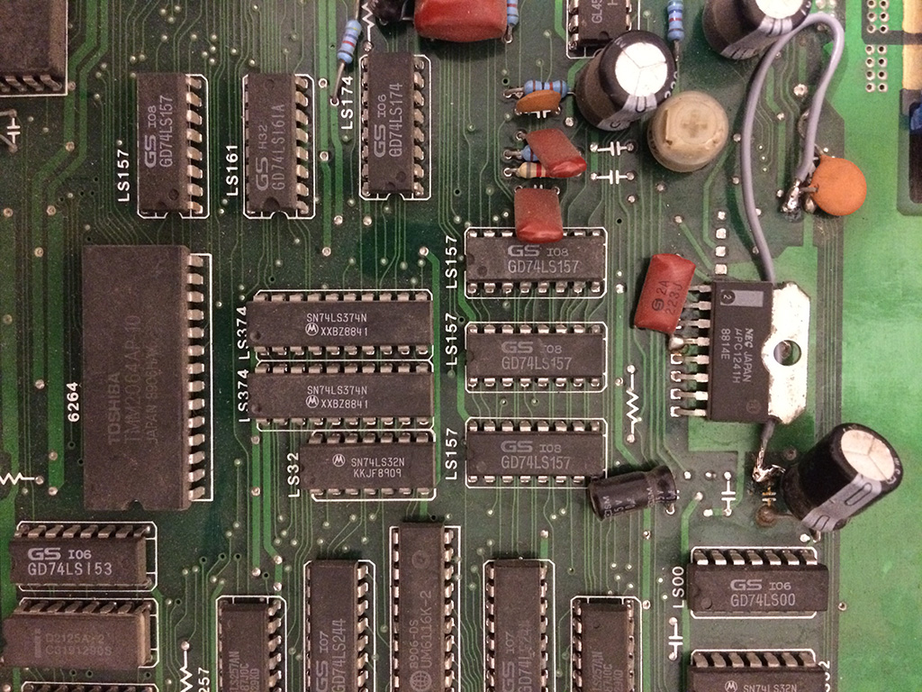
The game booted perfectly but was missing some parts of graphics , road and cars

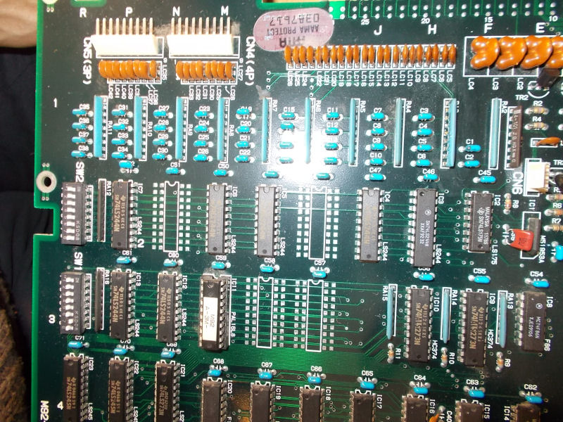
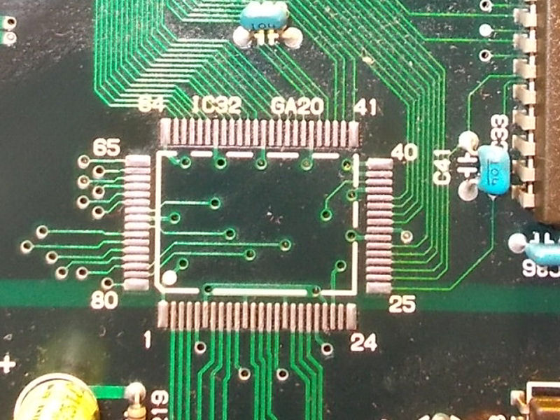
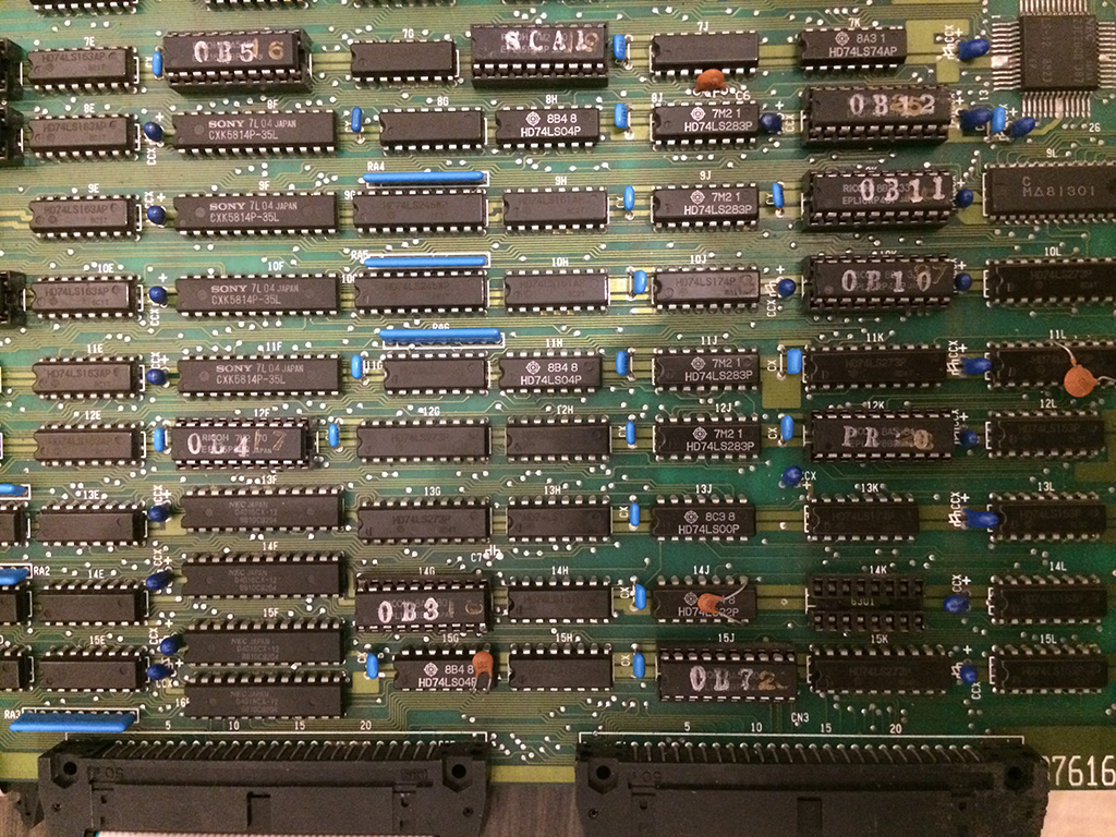
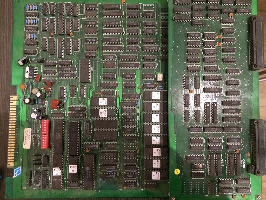
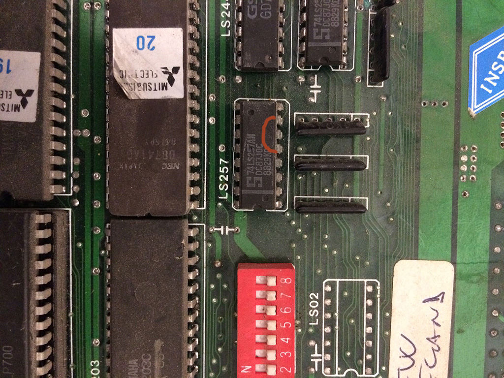
Upon closer inspection, there was a missing bprom in position 14k.
Since I had a working Mad Gear, I borrowed the bprom and installed on the faulty Mad Gear just to see if the chip was taken away because the game had other problems.
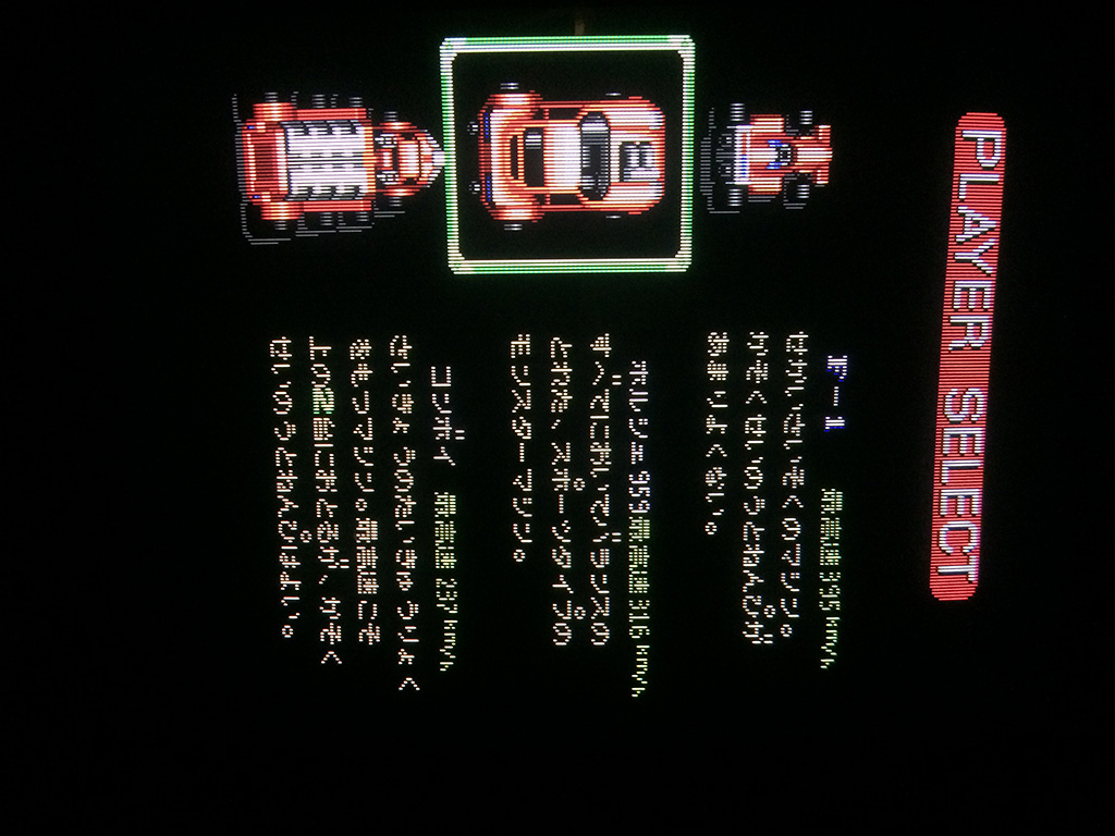
To my surprise, with the bprom in place, the game was perfectly working with all graphics in place.
It could have been an easy repair but bproms are discontinued since 30 years and nowadays they are nearly impossible to find empty: they are otp chips so once programmed they cannot be erased!
In any case I did a research on ebay and there was no one selling the same kind of bprom needed for Mad Gear which is a 82s129 (equal to 6301 or 7052, depending on the manufacturer).
Next step was to find a way to reproduce it.
Bproms have small capacity but they have a fast access time (less than 50ns) and for that reason they are used often for decoding graphics.
Some OTP roms, such as 27256 or 27512 , have fast access times and can be used in place of bproms by just burning the binary file into them but the problem is that you have to build an adapter because the pinout is different and also the size of the chip itself is much bigger.
The other solution , more elegant and less invasive , is to reproduce the content of the Bprom into a GAL (Generic array logic). This has been done before by other people to reproduce some bproms but they had programming skills which I don’t have.
My friend Caius some months ago pointed me to a blog of a guy who programmed an alternate software for the TOP2005 chinese programmer which had also the ability to produce equations for a GAL out of a bprom file.
Turned out that this was exactly what I had been looking for!
So first of all I would like to give full credit for this wonderful program to the guy who goes by the name of Elgen.
His blog is: https://elgensrepairs.blogspot.dk/
Facebook page: https://facebook.com/ElgensRepairs
Most important the software to convert bprom to GAL equations can be downloaded from here: https://bitbucket.org/Elgen/u2pa
Now back to the problem: my wish was to reproduce the bprom into a gal without building an adapter.
So I ran Elgen program on the bprom file taken from Mame which produced the GAL equations.
I then started the program WINCUPL by Atmel (can be downloaded free from here: https://www.atmel.com/tools/WINCUPL.aspx ) in order to produce the JED file (fuses list) out of the PLD equations (source code) so that a programmer could burn the GAL chip.
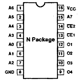
On the WINCUPL program I declared the inputs (addresses) and outputs (datas) in the same pinout standard of the original bprom chip so that I could avoid bulding an adapter:

We don’t have to worry about CE1 and 2 because normally they are tied to GND
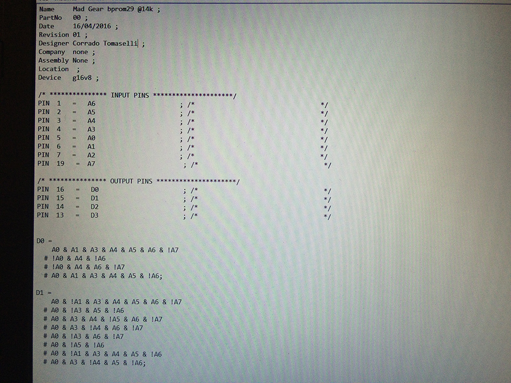
After copying and past the equations produced by Elgen program into the PLD project of WINCUPL and minimizing the equations using Expresso algorithm I got this:
Since the equations were not complex in this case, I could use the smaller 20 pins GAL chip, a 16V8 instead of the bigger 24 pins 22V10.
You can see that the GAL file used only 2 data lines instead of the 4 of the bprom file.
At this time you can notice that the BPROM chip is only 16 pins while the GAL 16V8 is 20 pins.
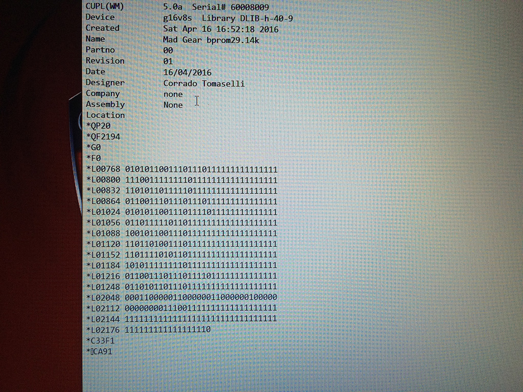
After compiling succesfully I got my JED file to be used in a common programmer supporting PLD files:
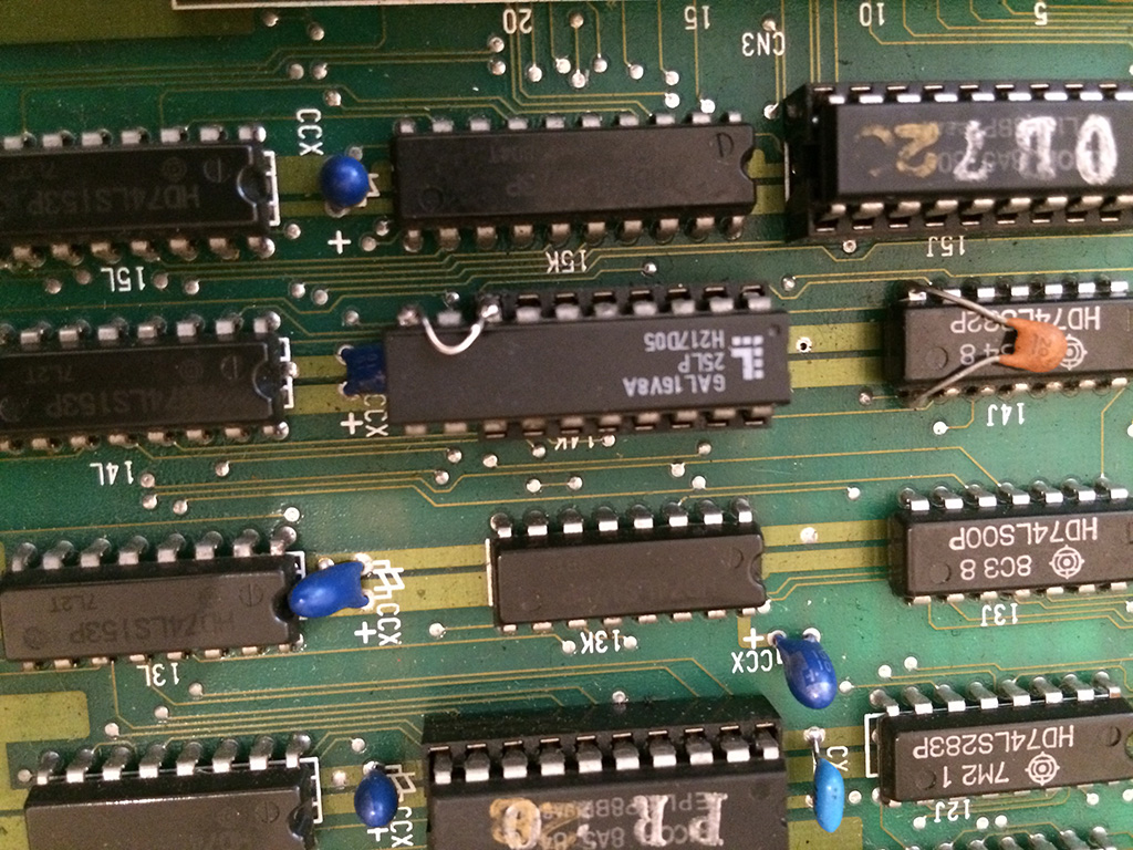
With the way I declared inputs and outputs, I could install the GAL chip on the socket, leaving out 4 bottom pins.
In order to power it, I only needed to solder a jump wire from pin 10 to pin 8 for the GND! Very easy and less invasive!
Now the smoke test:
Game fully restored!
Again I would like to thanks Elgen, without his program I couldn’t repair this game, but more over, it’s a very important tool for everyone who has missing or broken Bproms because they are really near impossible to find empty nowadays