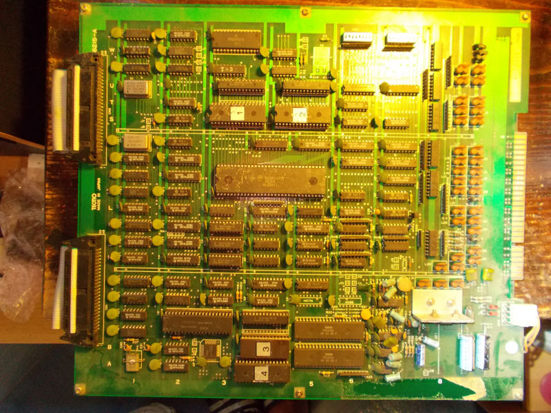
I picked up an original Street Fighter II CE PCB off eBay with minor video issues. The seller also claimed that the sound didn’t work but this turned out to be the volume pot turned all the way down.
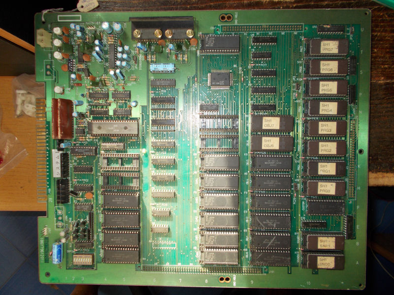
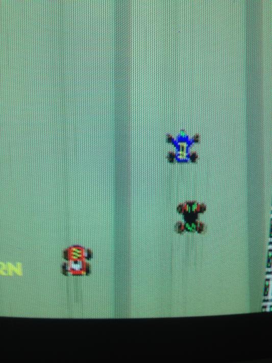
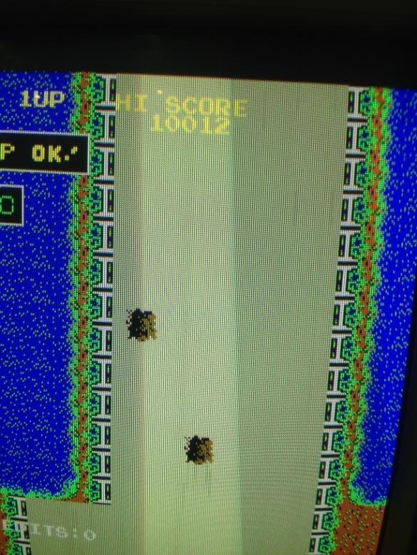
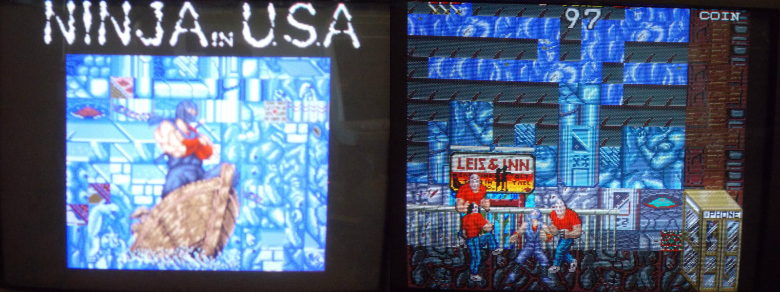
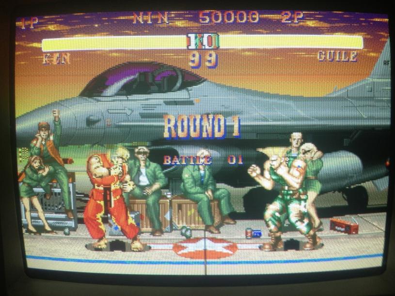
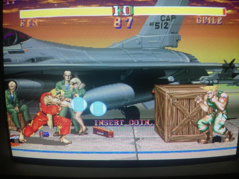
Screen was full of jail bars and graphics corruption. Tested all mask roms and confirmed two bad ones ( s92-1M & s92-2M ). These chips appeared to have some liquid spilled on them ( coffee or some other warm drink ) at some point. Several pins on both mask roms were corroded badly. I replaced the bad mask roms & burned the correct data on two EPROMS ( 27c400s ). This cleared up the jail bars however graphics corruption was still present, see the following screen shots below.
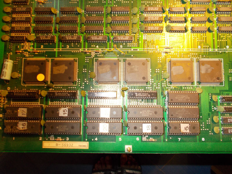
After two or three minutes of playing corruption almost completely disappeared. The problem could only be reproduced by turning the unit off for a few minutes and back on again. I replaced three mask rom IC sockets which were also damaged from exposure to the moisture but there was no change in symptoms, this left me scratching my head.
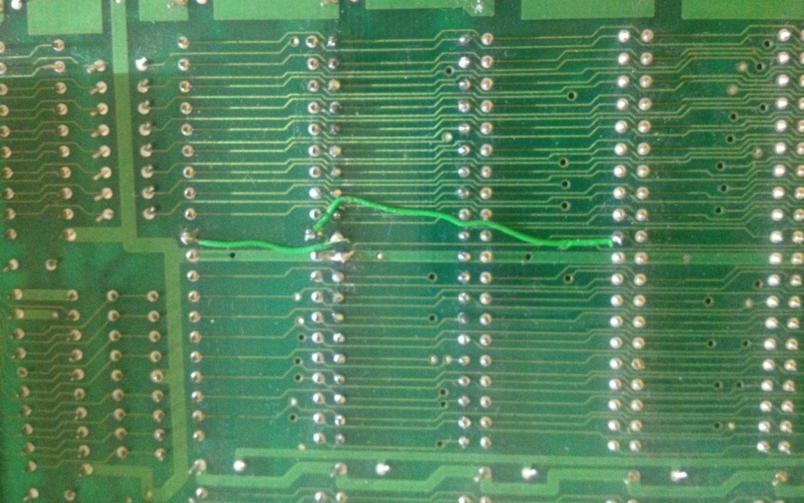
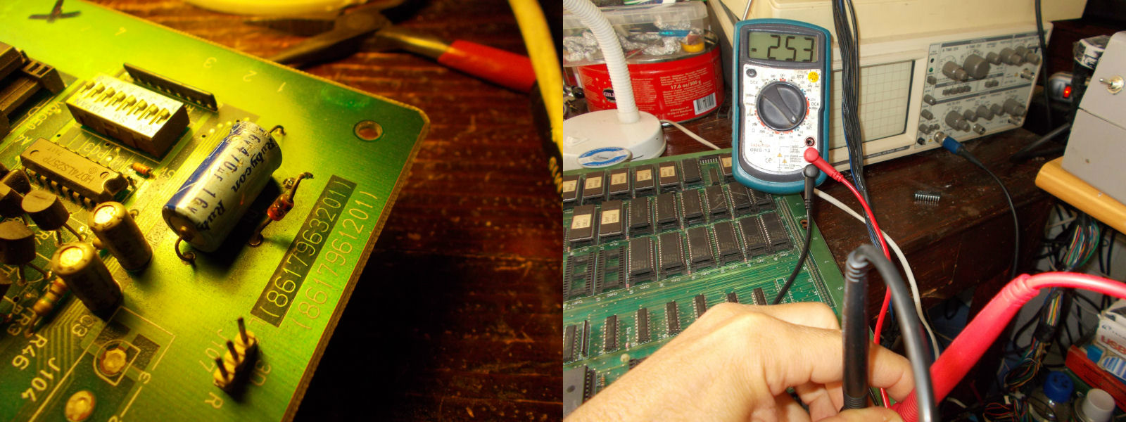
I flexed the B board between at the mask rom area using some pressure from my index finger and the graphics came up better than before as I applied pressure. I knew I was dealing with a break somewhere on the component side of the PCB underneath the sockets. I put the game in test mode & probed the each pin on the mask roms. Eventually I reached pin 31 ( ByteVPP ) on s92-2M, as my probe made contact to it, the sprites transitioned/flickered between looking correct & then glitchy.
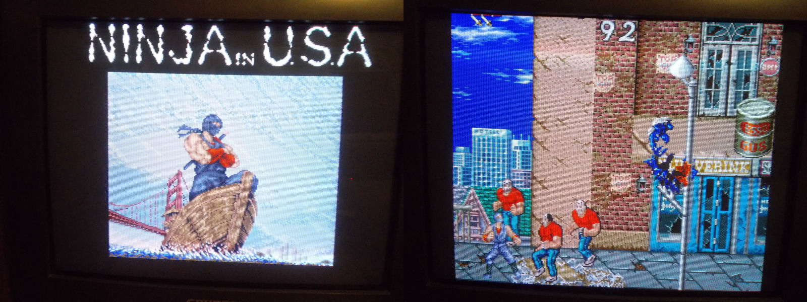
I turned the game off & set my DMM to continuity mode. I measured nothing between s92-1M & s92-2M on pin 31, an obvious break here. I patched the break with some AWG wire & hooked it up on the solder side. This fixed the video issue somewhat but I also detected another break on the solder side between s92-1M & s92-3M ( on pin 10 ) which I patched as well. This fixed the game and my graphics came back 100% complete.