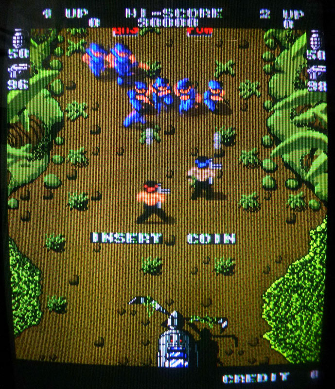
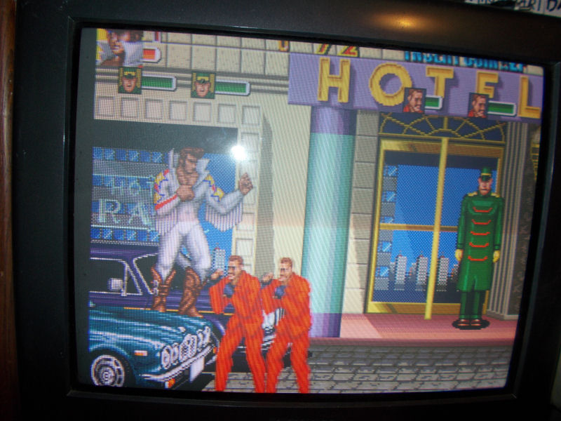
I recently repaired a friend’s dead Ikari Warriors PCB.
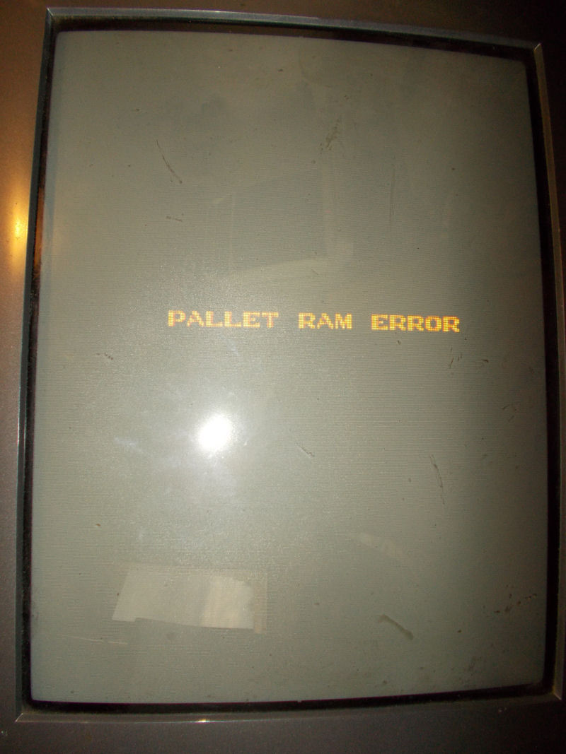
It had a black screen on boot with no sound.
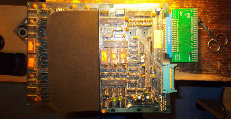
This game is a bit tough to diagnose as it is composed of 3 PCBs mounted on each other. Fortunately I had another working Ikari Warriors PCB so I could swap boards in order to track which board(s) were faulty. Top board and middle board were tested ok on my working Ikari so, fortunately, only the bottom board was faulty.
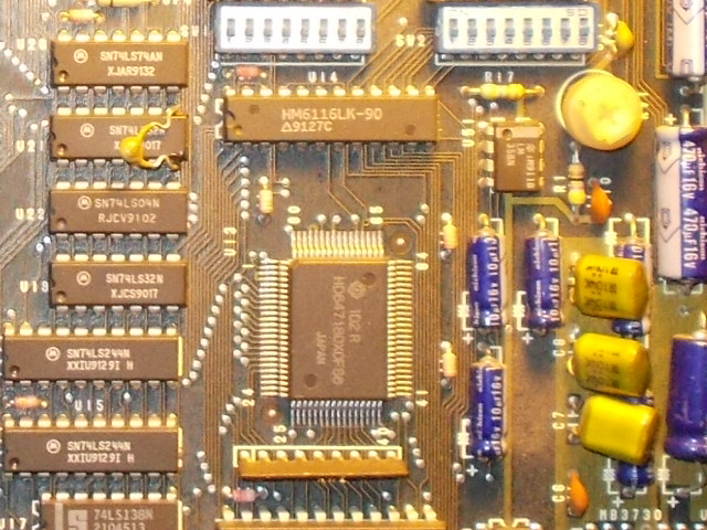
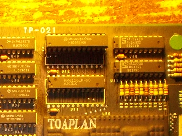
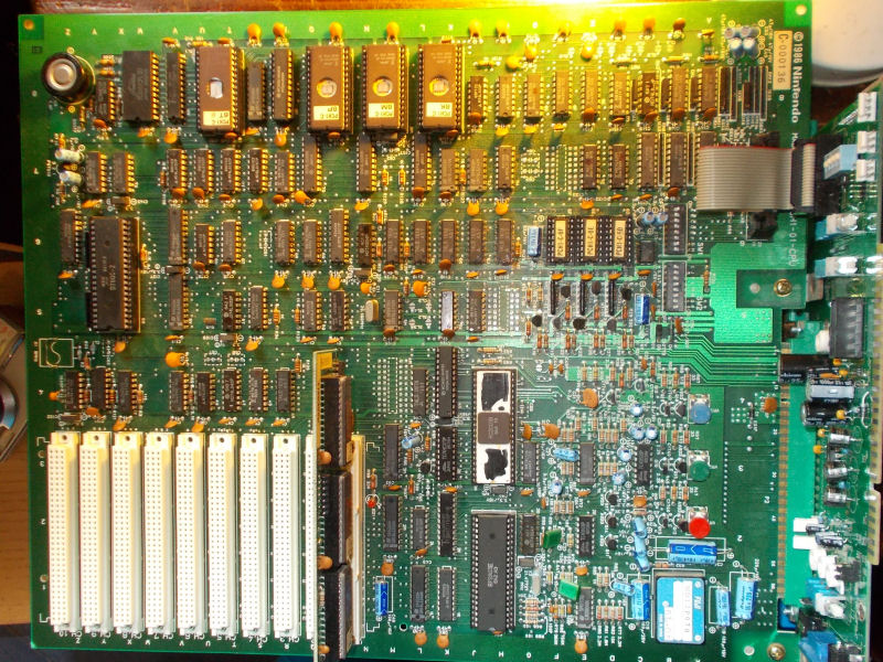
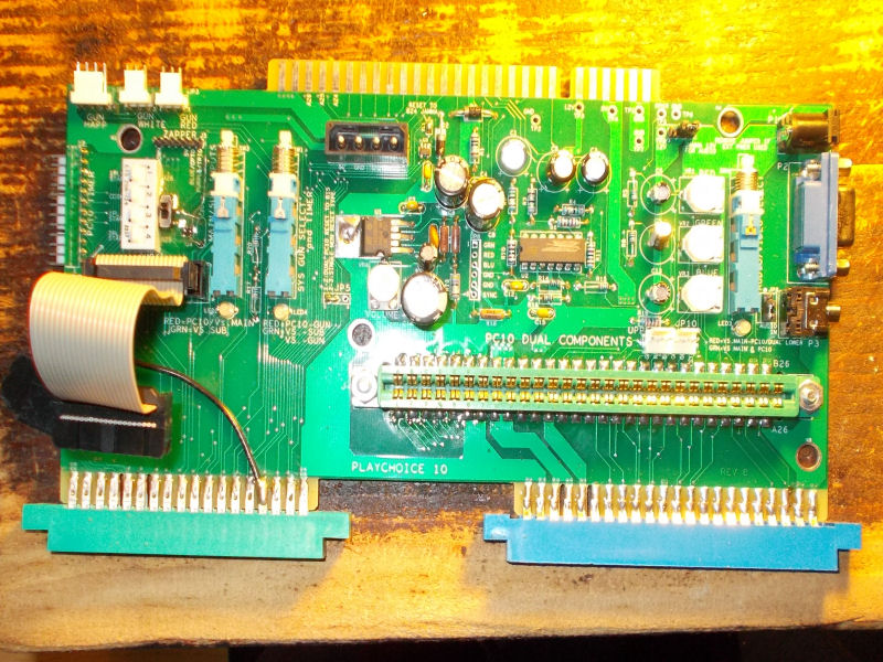
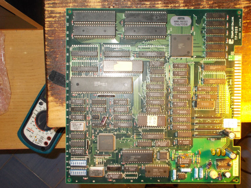
Here is a picture of the faulty bottom board with the faulty chips I replaced in red. I’ll explain every step below.
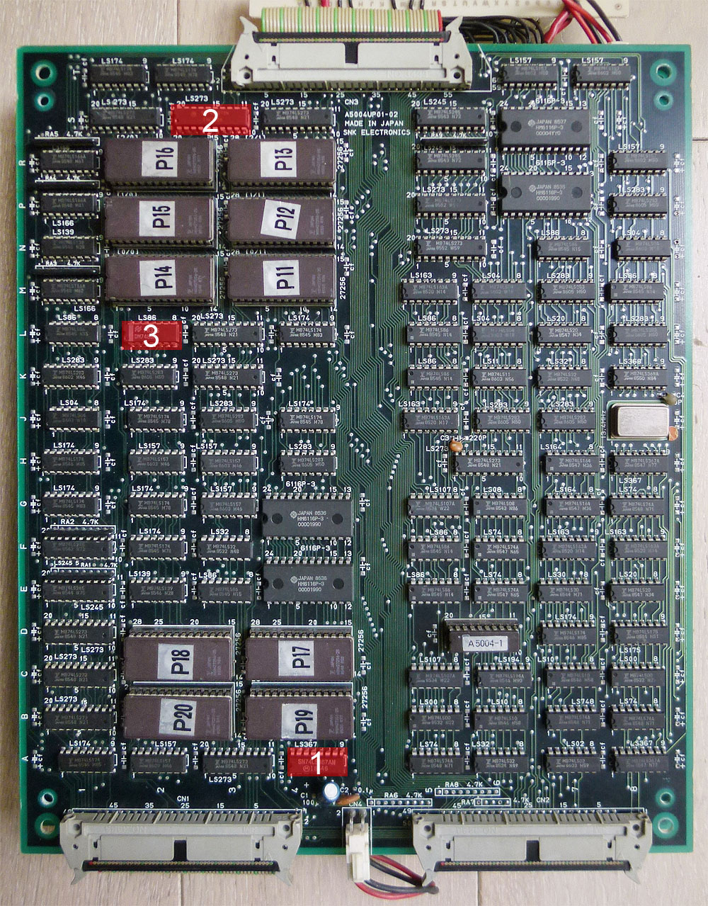
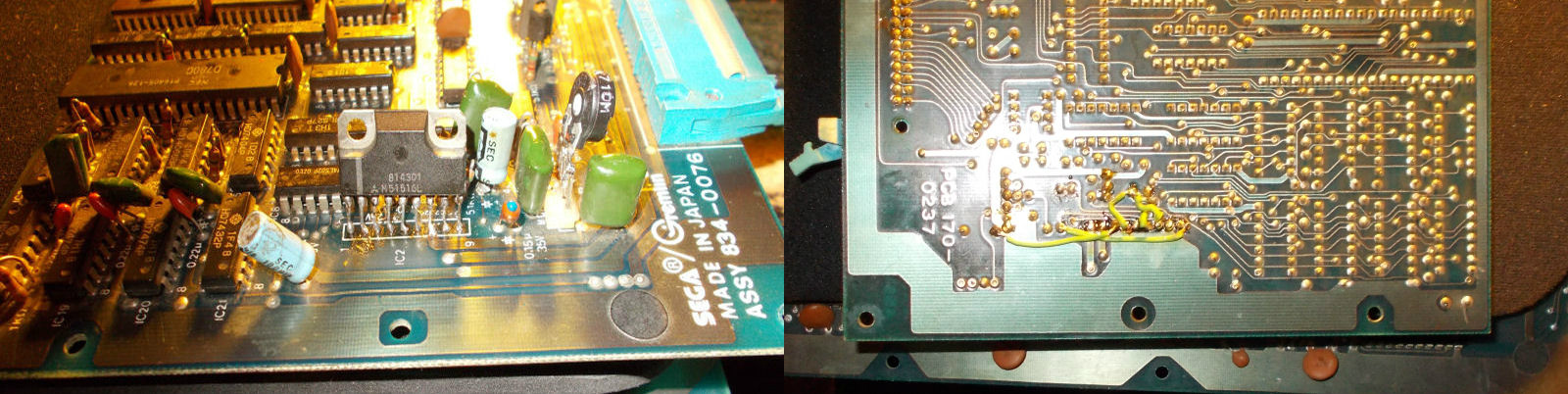
1. There was something that was avoiding the game to boot on that board. First, in order to reduce the field of investigation, I disconnected each of the 3 connectors on my working Ikari to see when the game was booting or not. It was booting only with the two bottom connectors on, the one above is only related to the sprites and doesn’t prevent the game to run. So I needed to focus on and around these two bottom connectors. I checked the signals on every pins to track a possible missing signal. After comparing the signals, I found one that was “floating” on my faulty board and was pulsing on my working board. This was connected to pin 9 of the 74LS367 (marked 1 on the PCB picture). Piggybacking a working chip on that one bring the game booting back again !
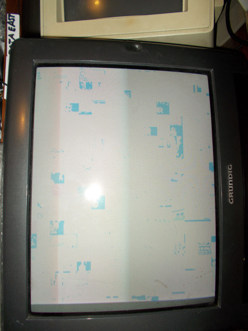
2. Well, the game worked but the characters had missing legs and were always looking down whatever movement you did, enemies had wrong visuals and background scrolling was jerky…
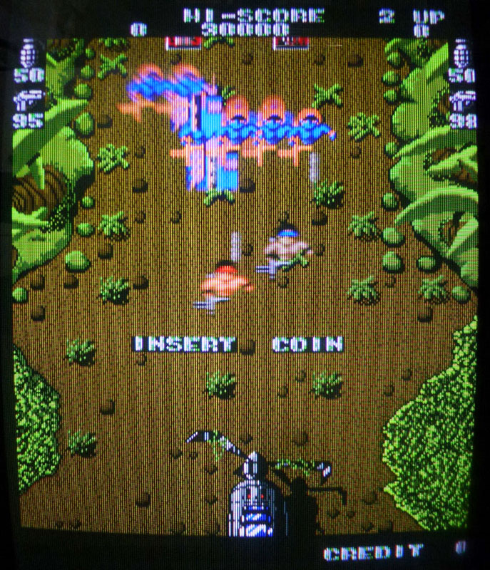
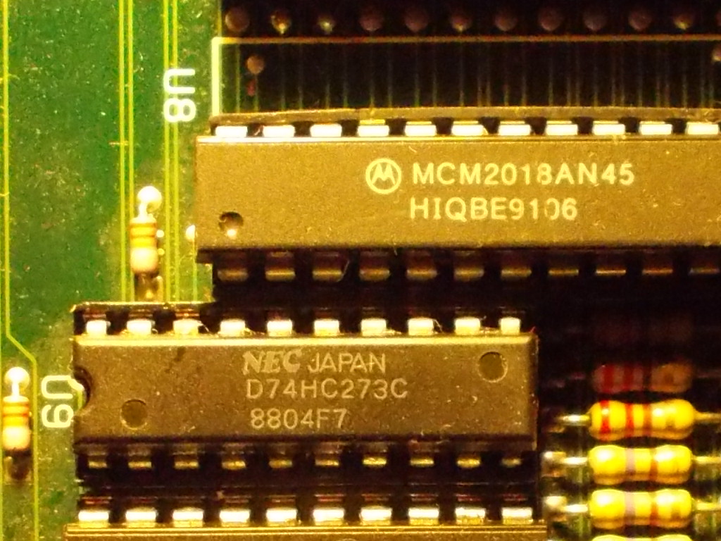
As previously seen, the sprites are related to the upper connector. I started to check the signals on the upper part of the board and quickly found a 74LS273 (marked 2 on the PCB picture) with a seemingly dead output (my working board confirmed this). Piggybacking the chip with a new one bring back the characters’ movements and visuals. I still had the jerky scrolling though…
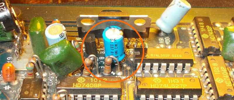
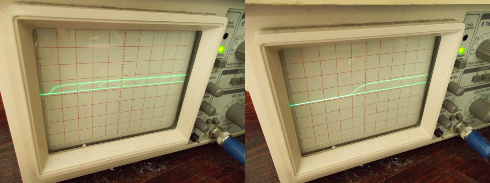
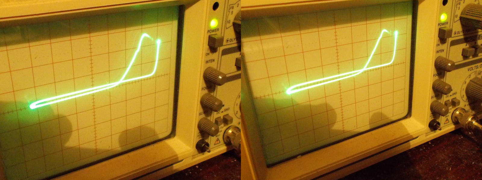
3. This one took a bit longer as I had no real idea where to look on the board for the chip that was responsible of this jerky scrolling. After more than an hour, comparing signals between the working and faulty boards, I found a suspicious signal on a 74LS86 (marked 3 on the PCB picture). This was indeed a dead output (pin 6). Piggybacking a good chip on it bring back the smooth scrolling.
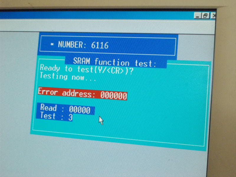
As an example, here is what the signal looked like on the pin 6 of that 74LS86 before and after replacement.
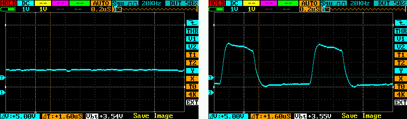
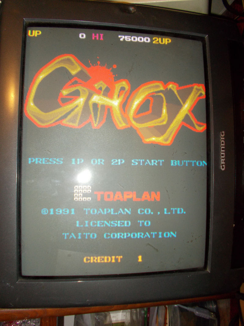
Board is now fully fixed.