PCB Repair LogsComments Off on Capcom CPS-B-01 C-BOARD repair log
Nov032015
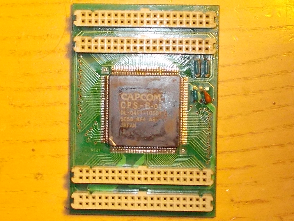
Just a quick (but quite important) fix.Got from my friend Josef this spare Capcom C-BOARD with CPS-B-01 ASIC on it:
Whatever game I tried with it, I got sprites issues.Strider for example:
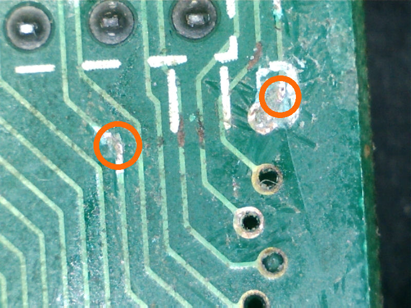
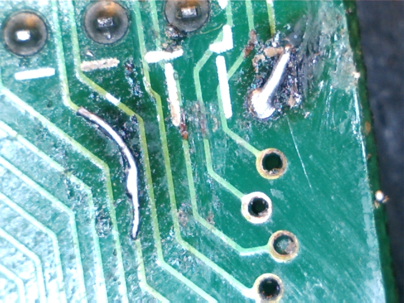
I was pretty sure the CPS-B-01 ASIC was bad, it’s very prone to failure IC but I decided to have a look at it.Doing a continuity test with my multimeter on solderside of the C-BOARD I found two broken traces:
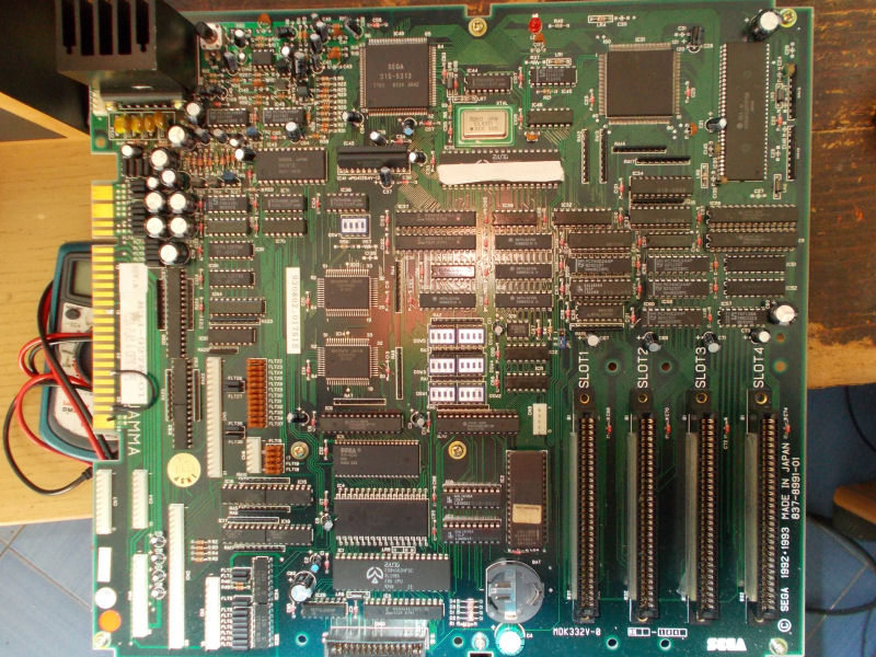
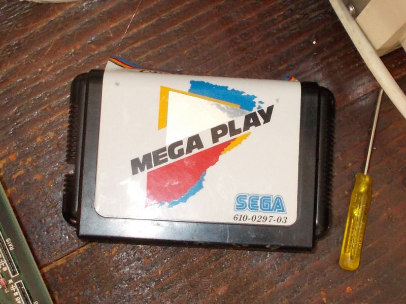
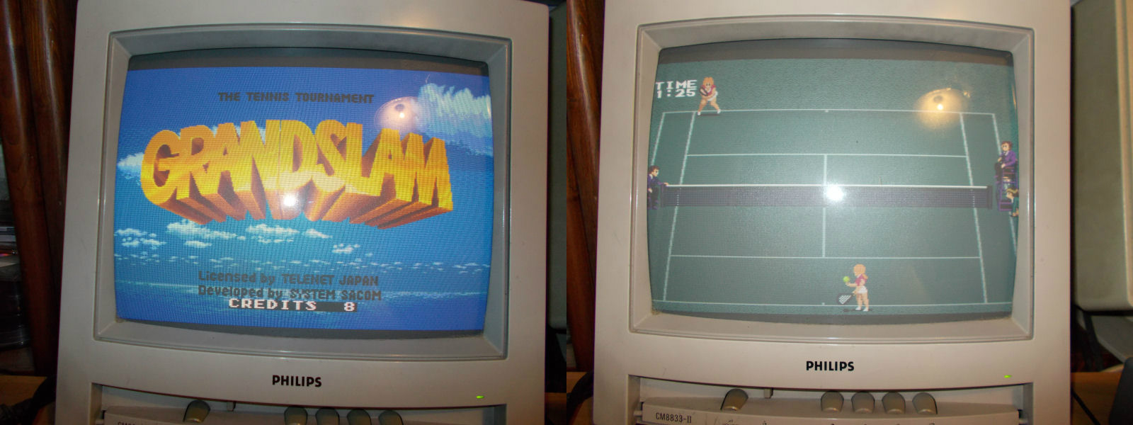
My friend Joachim sent me this Mega Play system for a repair:
The Mega Play is the name of a JAMMA-based arcade boardwith the ability to run Sega Mega Drive games. It was the second attempt by Sega to bring the home console to the arcades, following the Mega-Tech arcade system.Games come in form of cartridges:
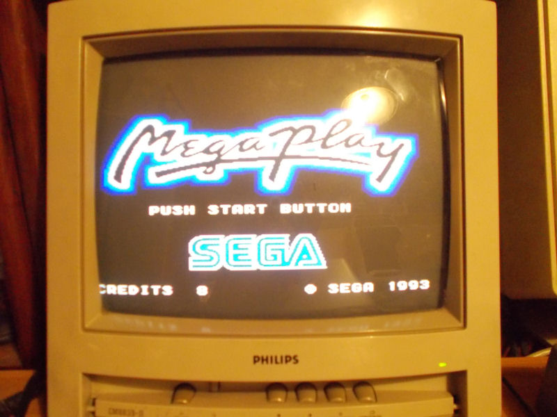
At power up the system booted but got stuck on the welcoming screen not loading cart in whatever slot was inserted:
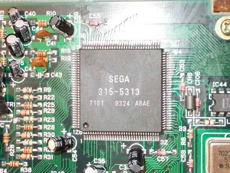
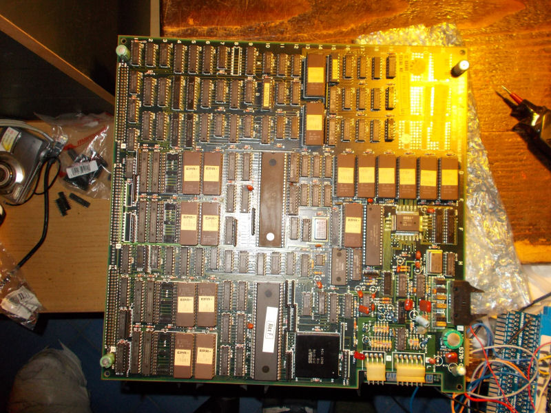
As I said, this system operates on the same core components that the Sega Genesis uses (plus some additional hardware, such as an additional Z80 and Master System VDP for driving an optional second monitor that displays a list of games installed).In particular there are two VDP (Video Display Processor) custom chips marked ‘315-5433’ and ‘315-5313’.When I went to inspect them, I found some lifted pins on the latter :
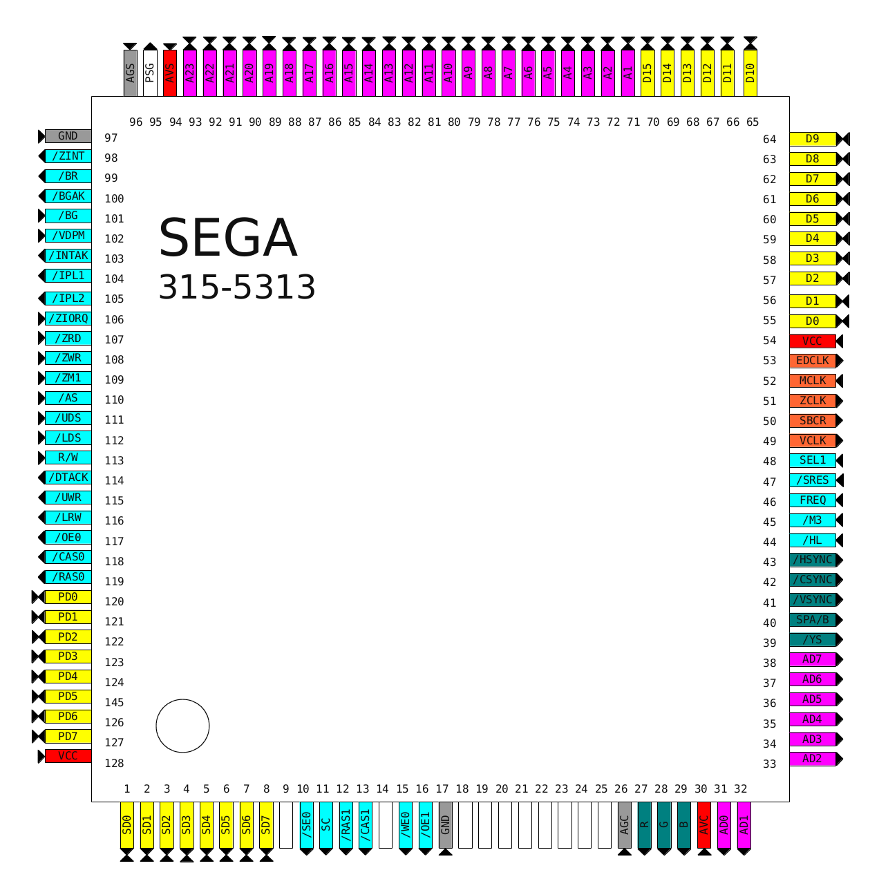
In particular lifted pins were some from 55 to 70 which are directly connected to the 68000 main CPU data bus :
I reflowed these pin and this was enough to fix the board:
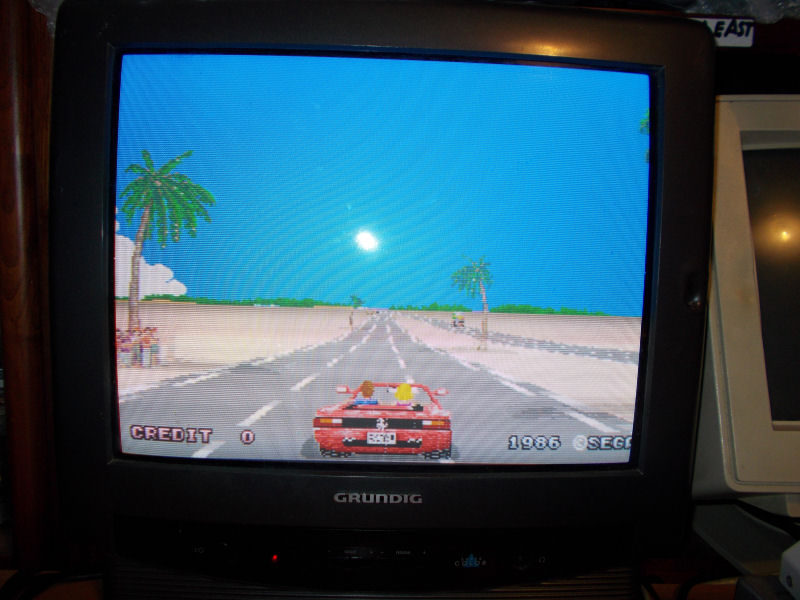
My friend Alexander sent me this original Sega Out Run PCB for a repair:
After adapting it to JAMMA I powered it up and I could noticed the defect :
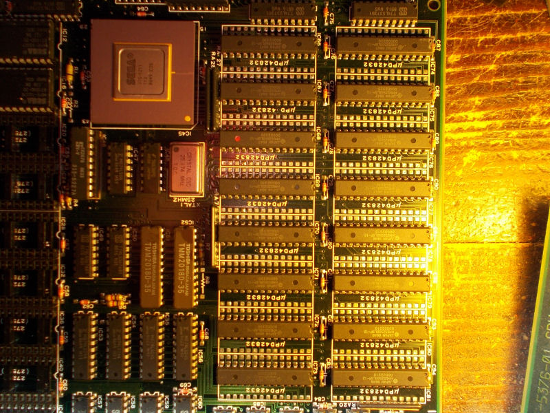
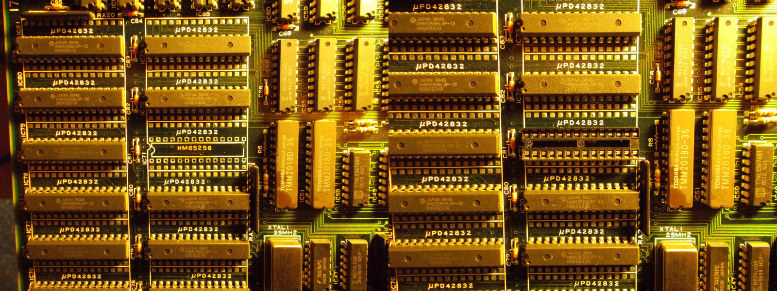
There were some dots on the screen in which I could recognize parts of sprites (lile a ghost images, I’d say).Since video board is the lower one, I could not reach with my logic probe or scope the involved circuitry made of the 315-5211custom Sprite Generator plus sixteen 62256 SRAMs chips :
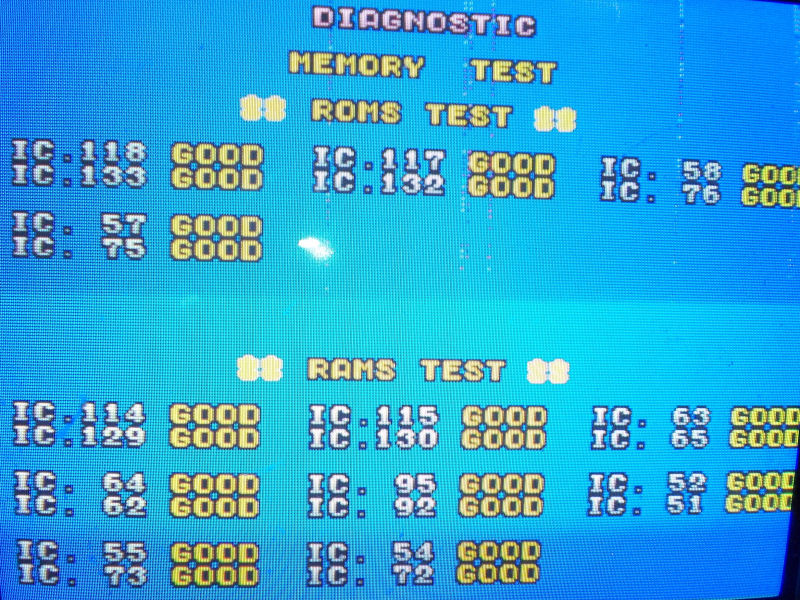
RAM test was successfully performed but didn’t cover all the chips :
So I went to piggyback each RAM chip and when i did it for the one @IC71, the issue was cleared:
Time to remove the chip and install socket:
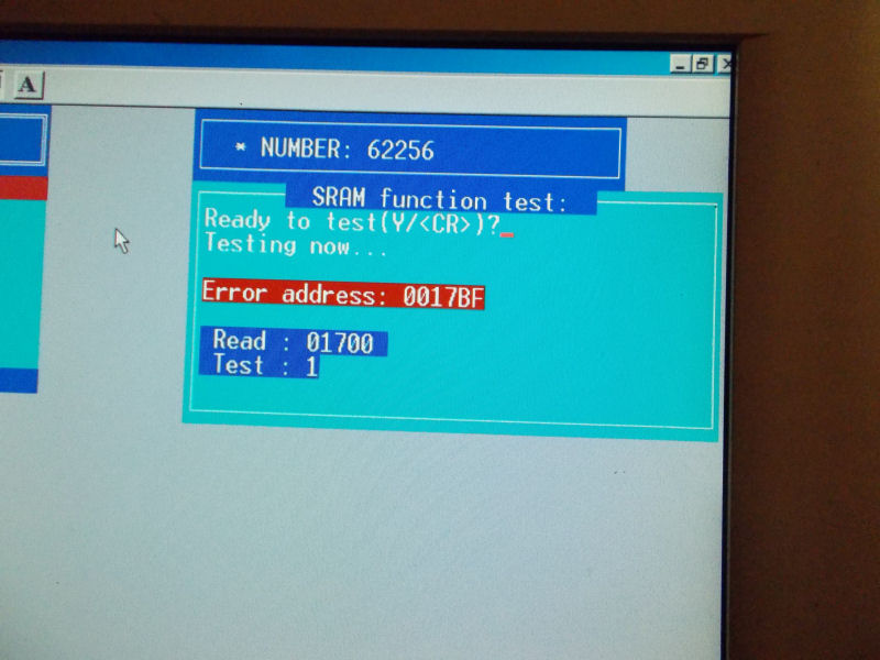
Obviously the desoldered chip didn’t pass the test on my programmer:
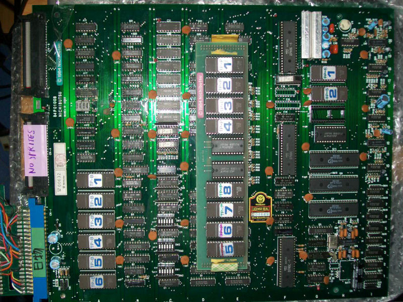
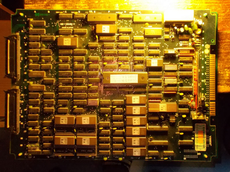
Another double Tube Panic PCB repair, with this so far fourth are the PCBs I repaired for my friend ‘robotype’ (you can find here the first log).Let’s start with first one :
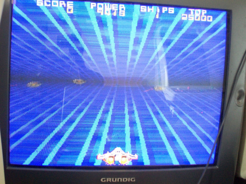
As label said, sprites were totally missing:
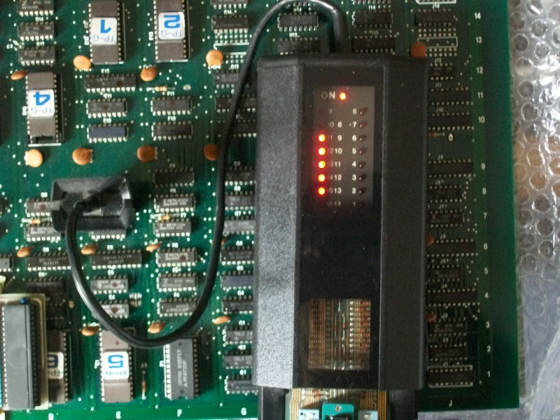
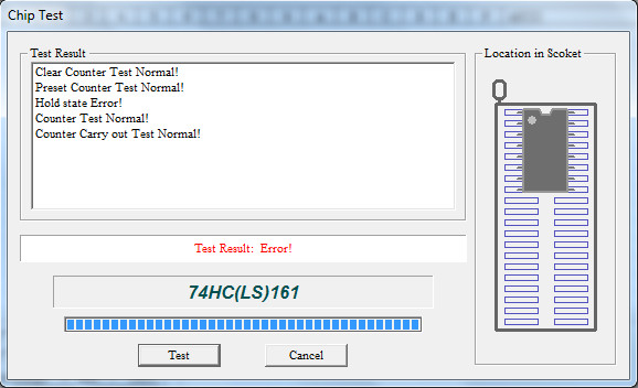
Sprites generation circuitry is located on the video board.ROMs were all good so, due lacks of schematics, I went to test components with my HP10529A logic comparator.When I clipped a 74LS161 counter @E8, comparator reported troubles on all its output pins:
It failed the out-of-circuit test:
With a good IC fitted, sprites came back :
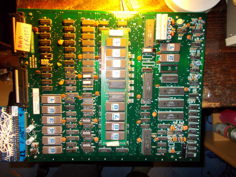
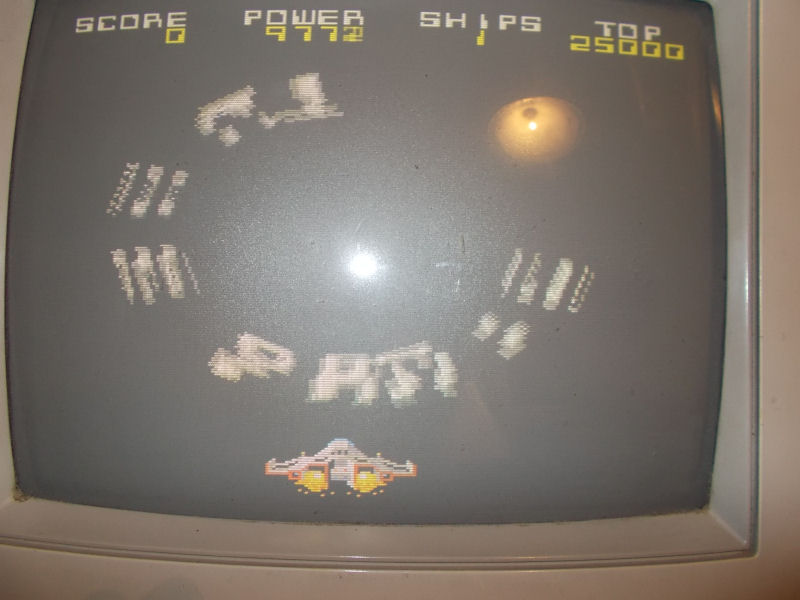
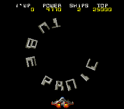
First board 100% fixed, let’s pass to the second one which was labeled with “BAD SPRITES” (it seems sprite issue is a common failure on all the Tube Panic PCBs) :
This was confirmed once powered the board up:
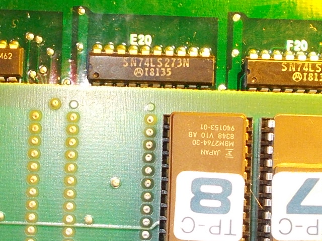
As in previous repair, I already knew where to look at.Sprites ROMs are located on video PCB in form of 8 2764 devices on a small piggyback board:
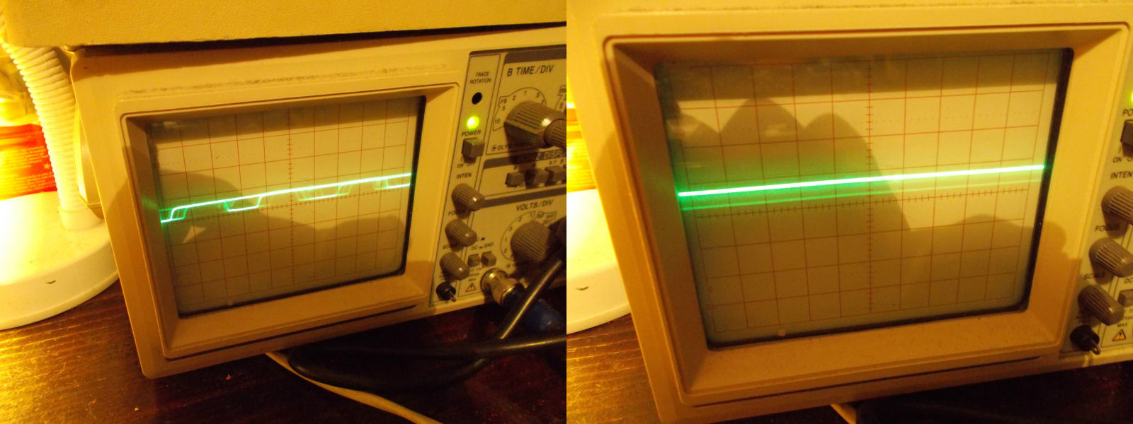
Data of these ROMs are latched by some 74LS273, when I went to probe with my analog scope the one @E20:
I found all outputs were bad compared to inputs:
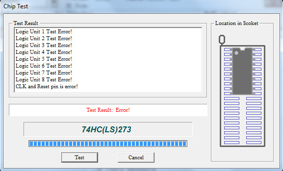
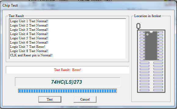
The IC failed when tested out-of-circuit:
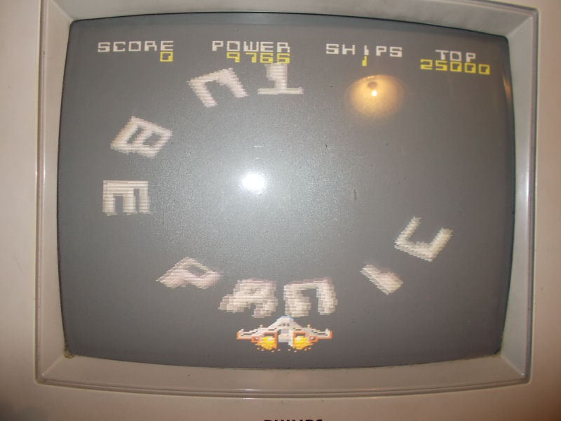
The sprites looked much better but still not perfect:
This is how it should be (MAME screenshot):
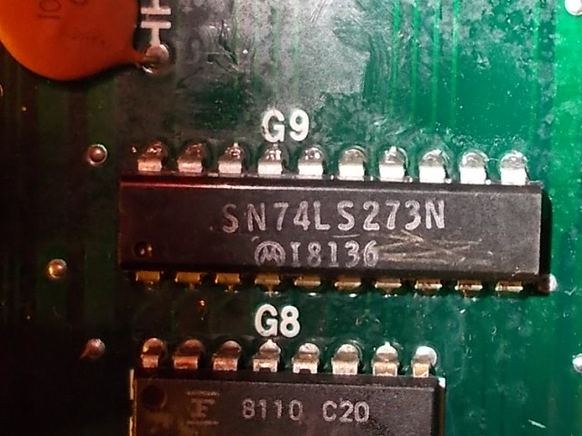
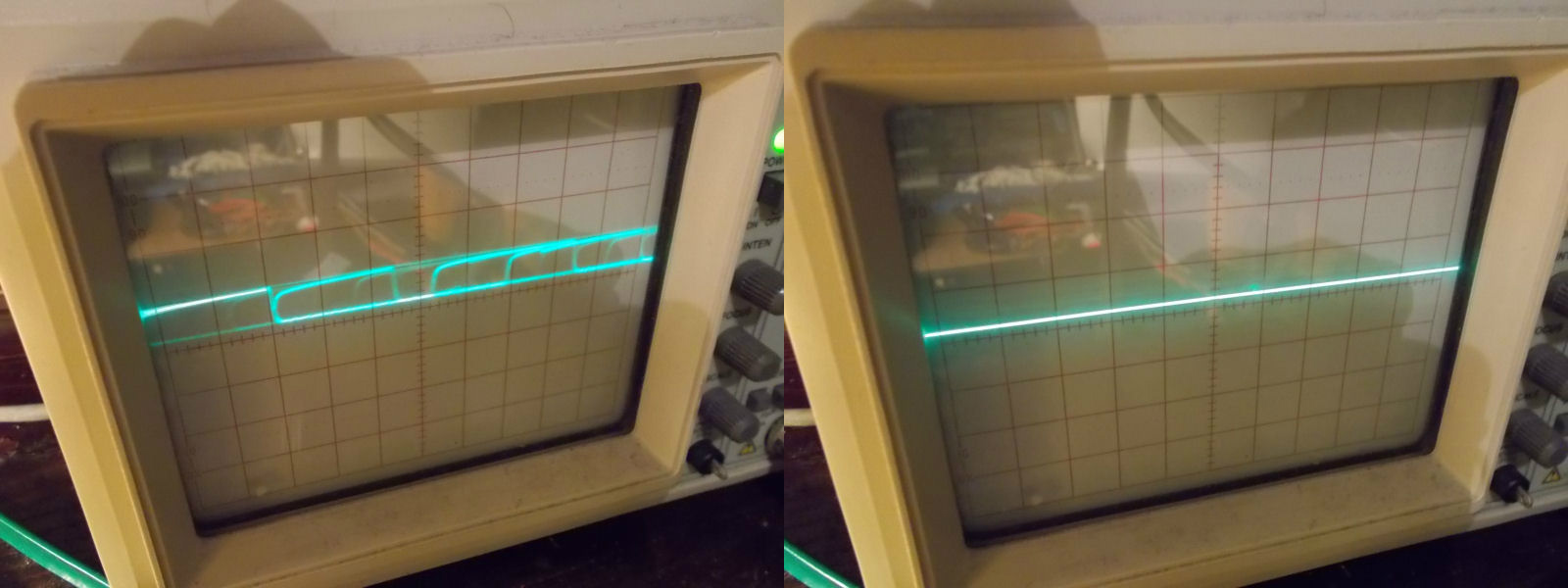
So I went to probe other ICs with my BK560A in circuit tester which reported trouble on pin 16 (output) of another 74LS273 @G9:
This was confirmed also by my scope, the output pin 16 was stuck low compared to its input pin 17:
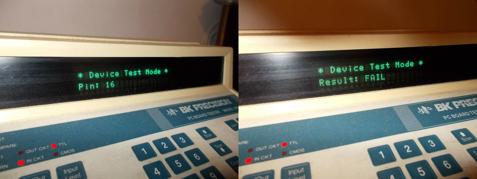
Once desolder and tested out-of-circuit, the IC failed in that specific gate:
PCB Repair LogsComments Off on Chelnov – Atomic Runner repair log
Oct252015
Another board from my friend ‘robotype’ and another quick fix.
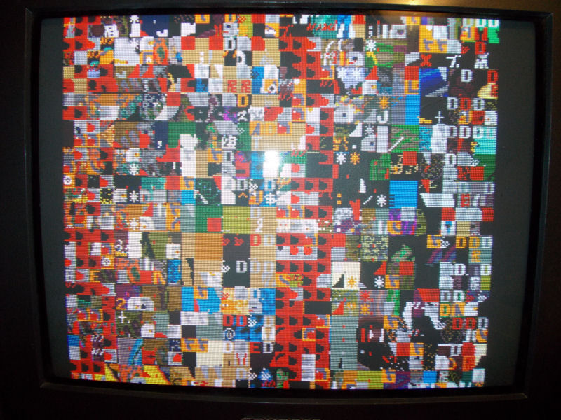
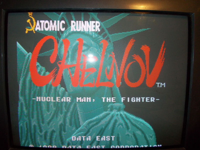
I got from him this Chelnov – Atomic Runner board :
It was stuck on this garbage screen:
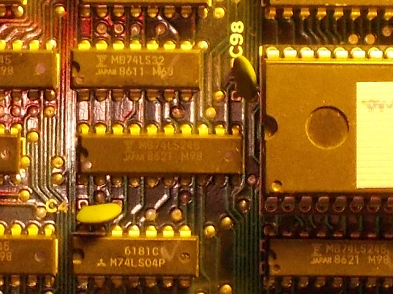
Main 68000 CPU busses were silent, no activity.Between 68000 and WORK RAMs (two 62256) there were some 74LS245 for communication between data buses.When I went to probe the one @F11, its pin 19 (output enable) was silent.I traced back this to another 74LS245 @E10 :
I piggybacked it and board booted fine :
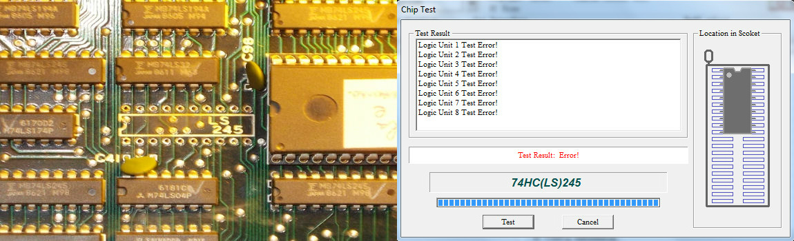
I removed the IC and tested it out-of-circuit where il failed (it was from Fujitsu manufacturer):
Board 100% fixed.
P.S.
For the uninitiated there is also an unreleased Sega Saturn port of this game (a copy has been afterwards located and disc image has been shared online).You can read more about here: