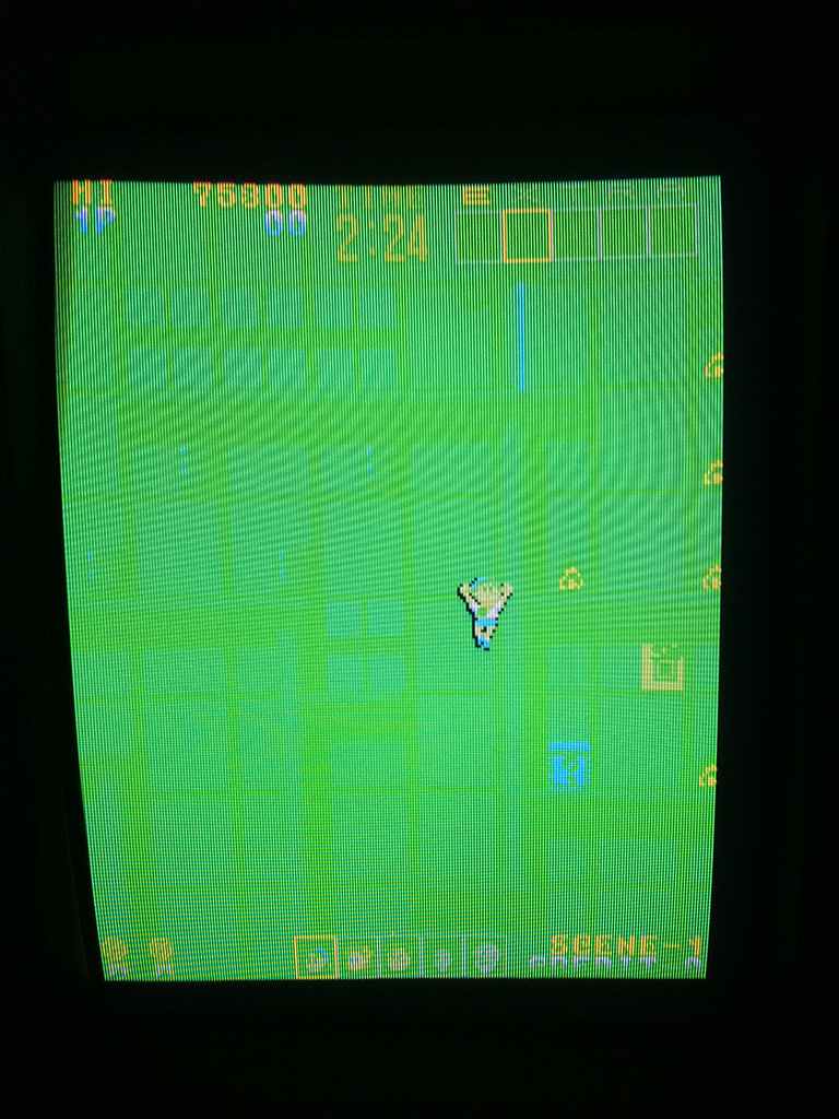
Initial Symptoms
- Static junk on screen, which changes between reboots.
- No sound or evidence that game is running in background.
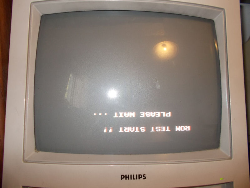
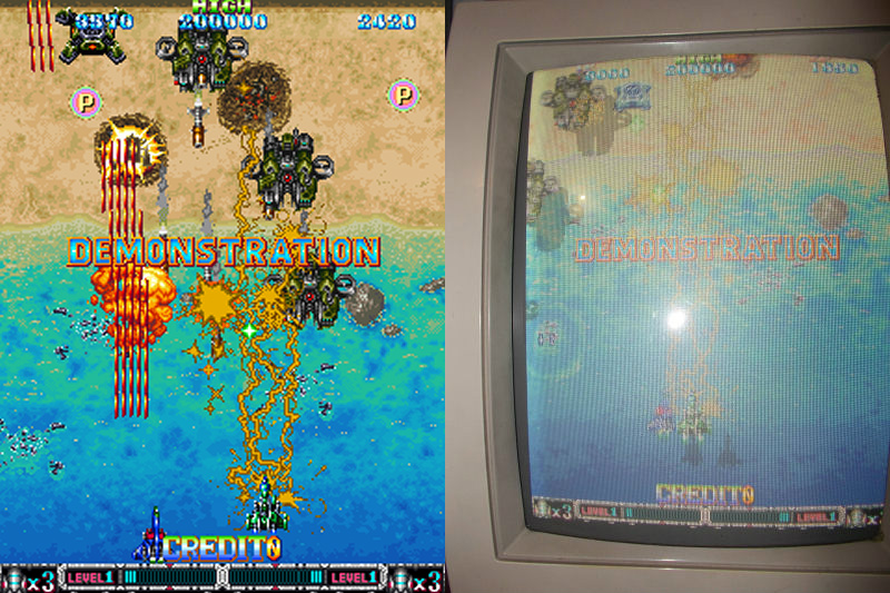
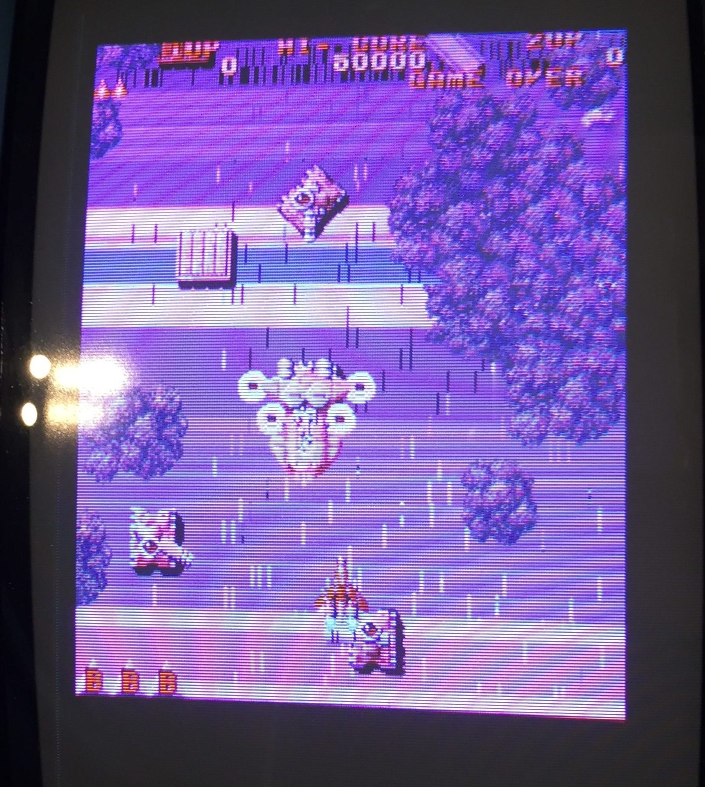
Sony PVM monitor wouldn’t sync in RGB mode, but would (for some reason) in Y/R-Y/B-Y mode.
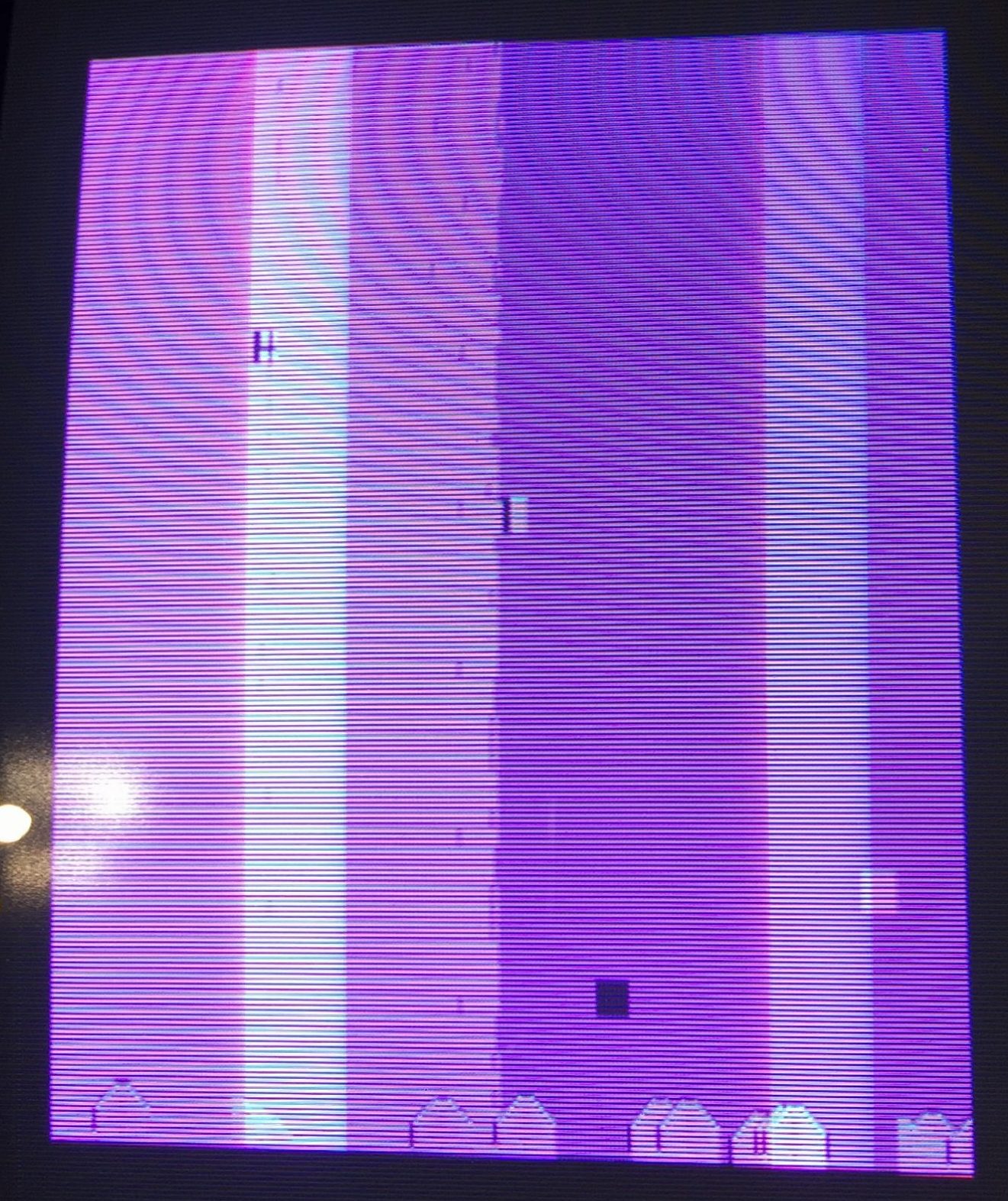
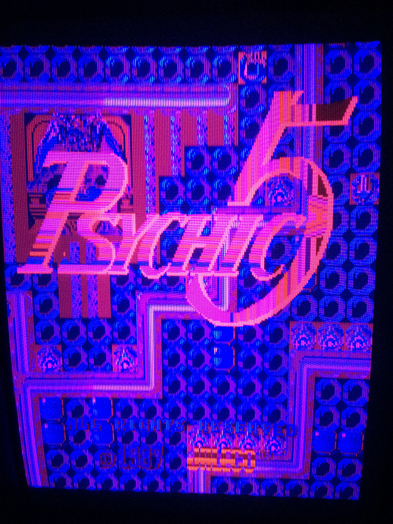
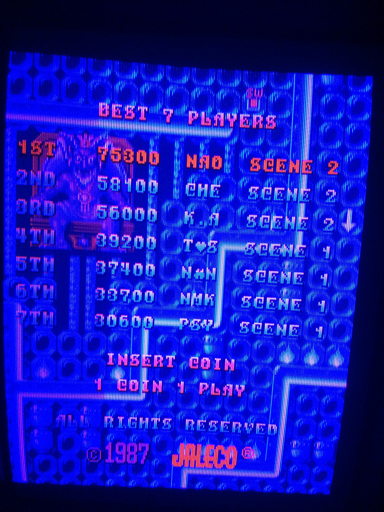
Random junk when powered. (purple image is due to monitor problem)
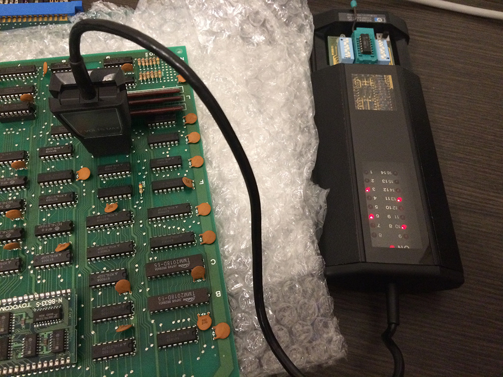
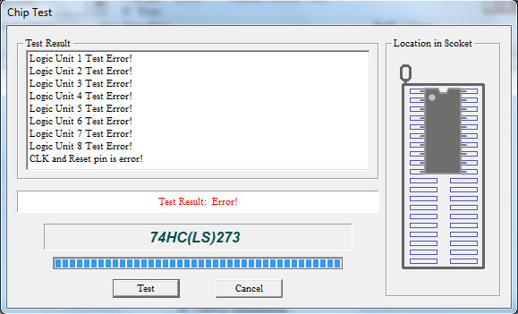
CPU Boot Problem
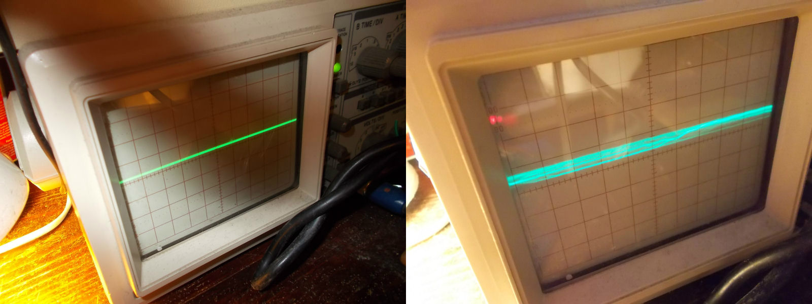
Probing CPU interrupts showed that sometimes V-Blank interrupts were active, sometimes not. Initial check of EPROMs showed that one was dead, but replacing did not solve the problem. Probing with a logic analyser showed that the data/address bus of the main CPU was pulsing, and the game wasn’t watchdogging so deeper investigation was required.
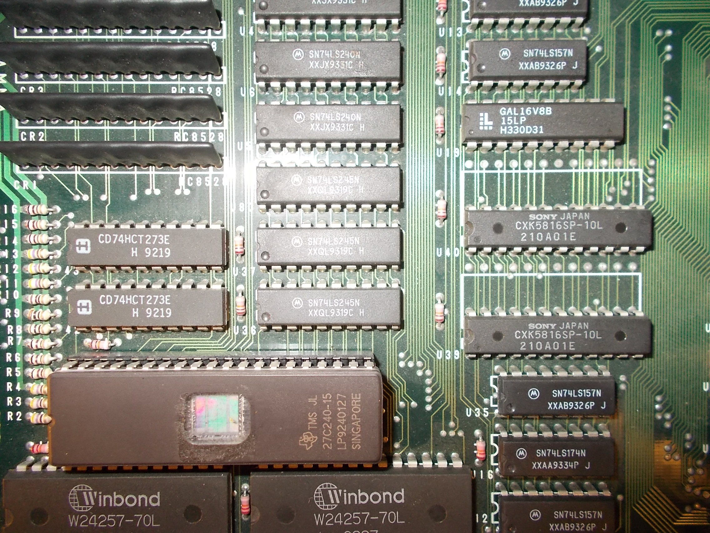
Tracing with a Saleae logic-8 showed that the first v-sync interrupt was getting acknowledged by the CPU, but subsequent interrupts were ignored. Digging futher I generated a partially complete address/data trace by the (shared) data+address bus and the bus status lines (BS0-2). Since my analyser is only 8-bits, I could only trace 5 data+address lines at once. I wrote a script to combine multiple traces using the bus status lines to synchronise the data. Luckily the behaviour was deterministic, and I could extract enough trace data (12-bits of both data and address) to work out a full trace by correlating the data with a mapped ROM dump from Mame. Doing this I found that one of the RAMs was faulty; The stack was getting corrupted, causing a ret instruction to jump to an unexpected program address. Swapping the program RAM resulted in the game booting.
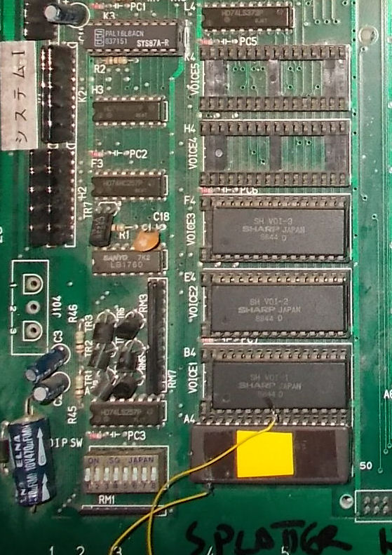
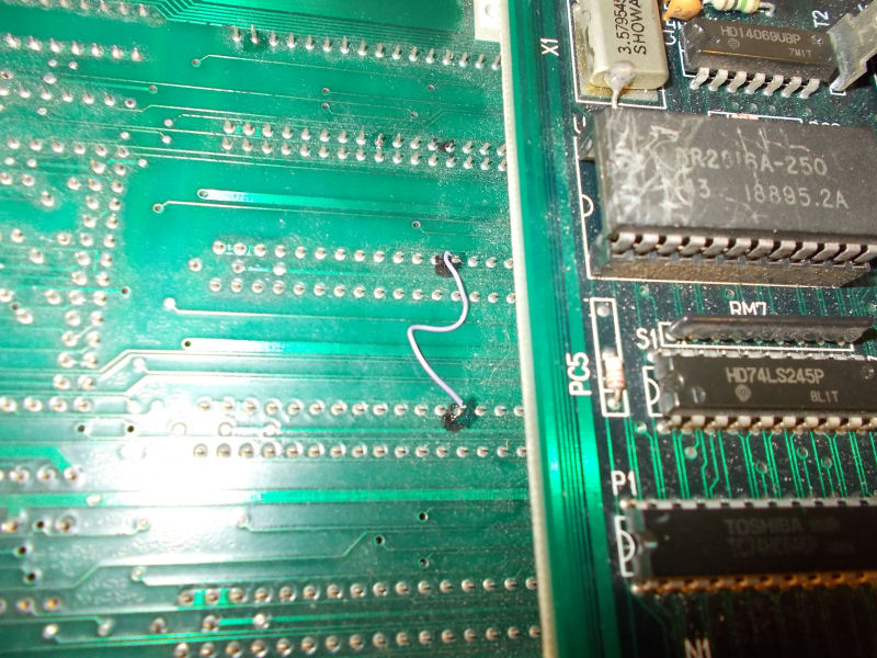
Bad SRAM of main CPU. Socketed and replaced.
New Symptoms:
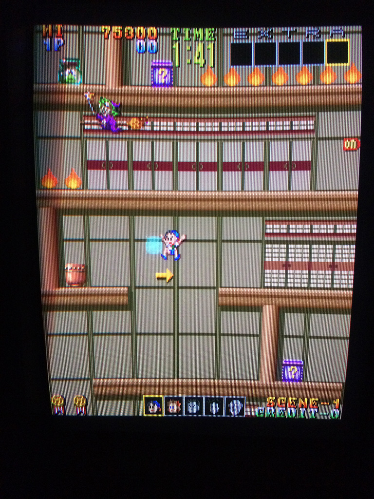
- Some tiles have flickering horizontal bars
- Some tiles seem to not change from top to bottom (in horizonal screen)
- Sound crackly and missing music
Background tiles are corrupted
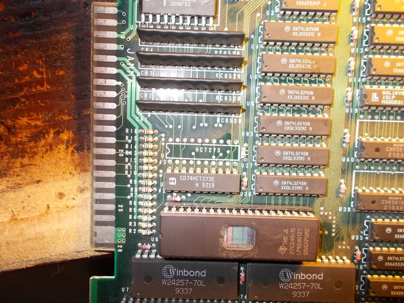
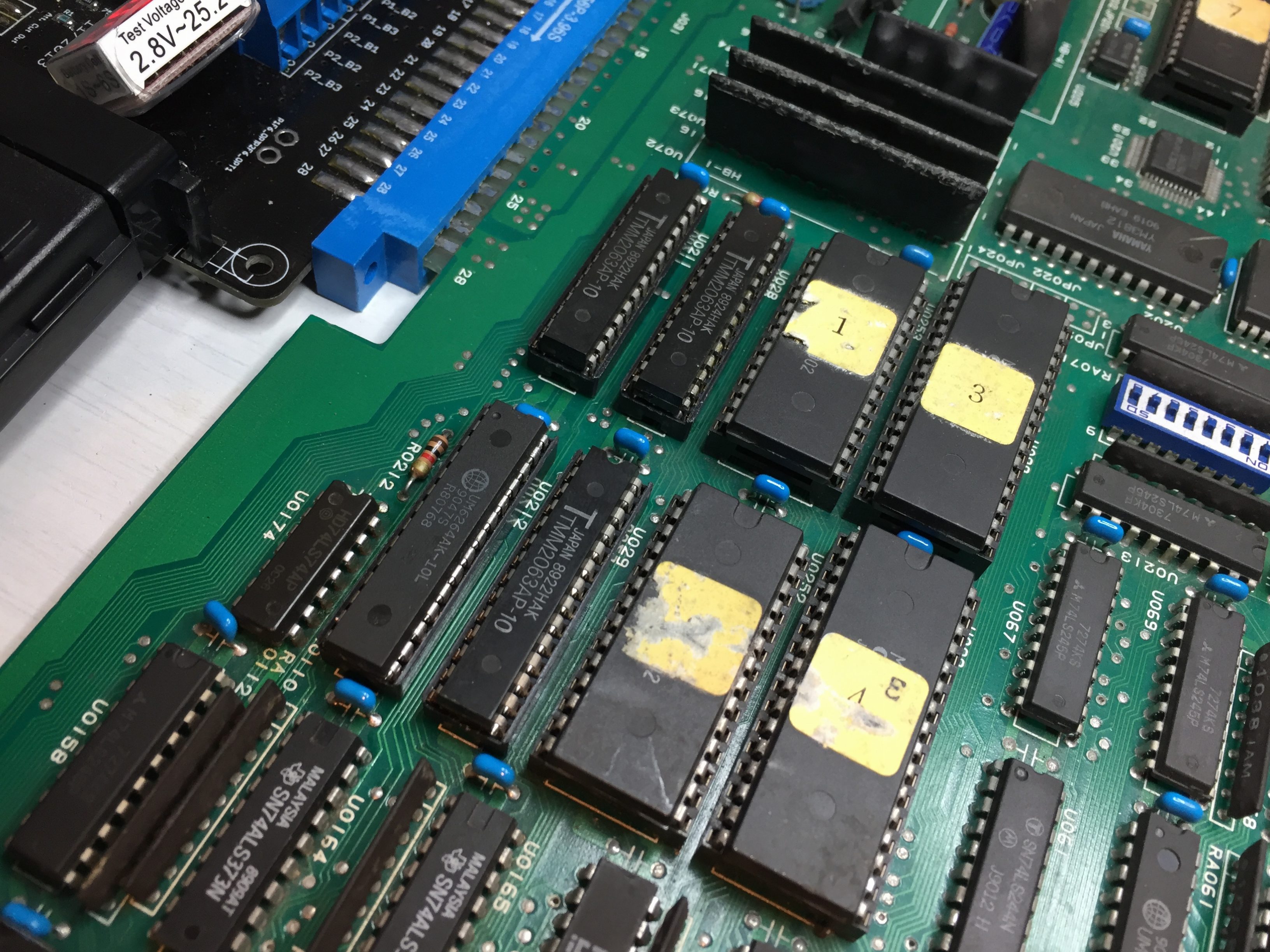
Tile Corruption Problem
Probing the tile ROMs shows that ROM U105 address lines 1-4 were floating. These were driven by the SEI0020BU custom chip at U102. Pulling the SEI0020BU and swapping it with it’s neighbour switched the tile corruption. Clearly the SEI0020BU was the cause of the problem. Annoyingly these aren’t easy to come by.
Reverse Engineering the SEI0020BU
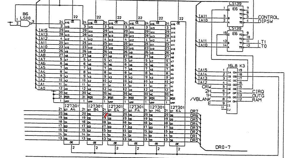
I guessed that the main function of the SEI0020BU was to drive the addresses of the ROM chip in the direction of the raster. I checked the connections of the SEI0020BU with a multimeter and worked out the function of each pin (see schematic below for more details).
Checking the Mame source confirmed that the address mapping for this chip corresponded with the x-axis scroll register. I guessed the purpose of the chip was to store an x-axis scroll offset and add that result to the raster x-position. I guessed that only 8 bits of shift were actually needed, and I knocked up a prototype on a breadboard, which seemed to work well.
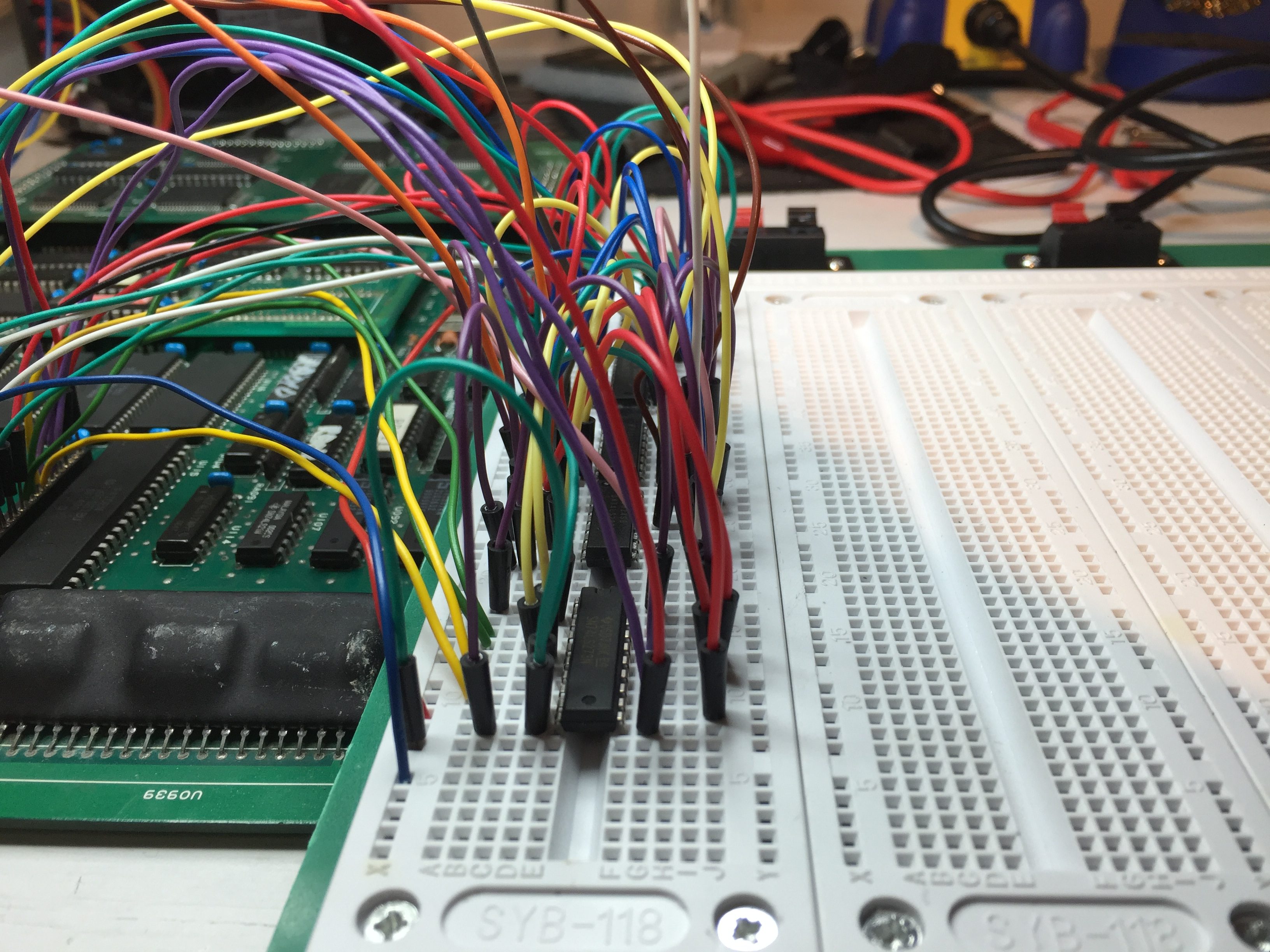
SEI0020BU breadboard prototype
With a working prototype, I got to work using CadSoft EAGLE (PCB CAD tool) to design a PCB daughterboard for a more permanent solution. The PCB was printed by Seeed, and delivered in a few weeks.
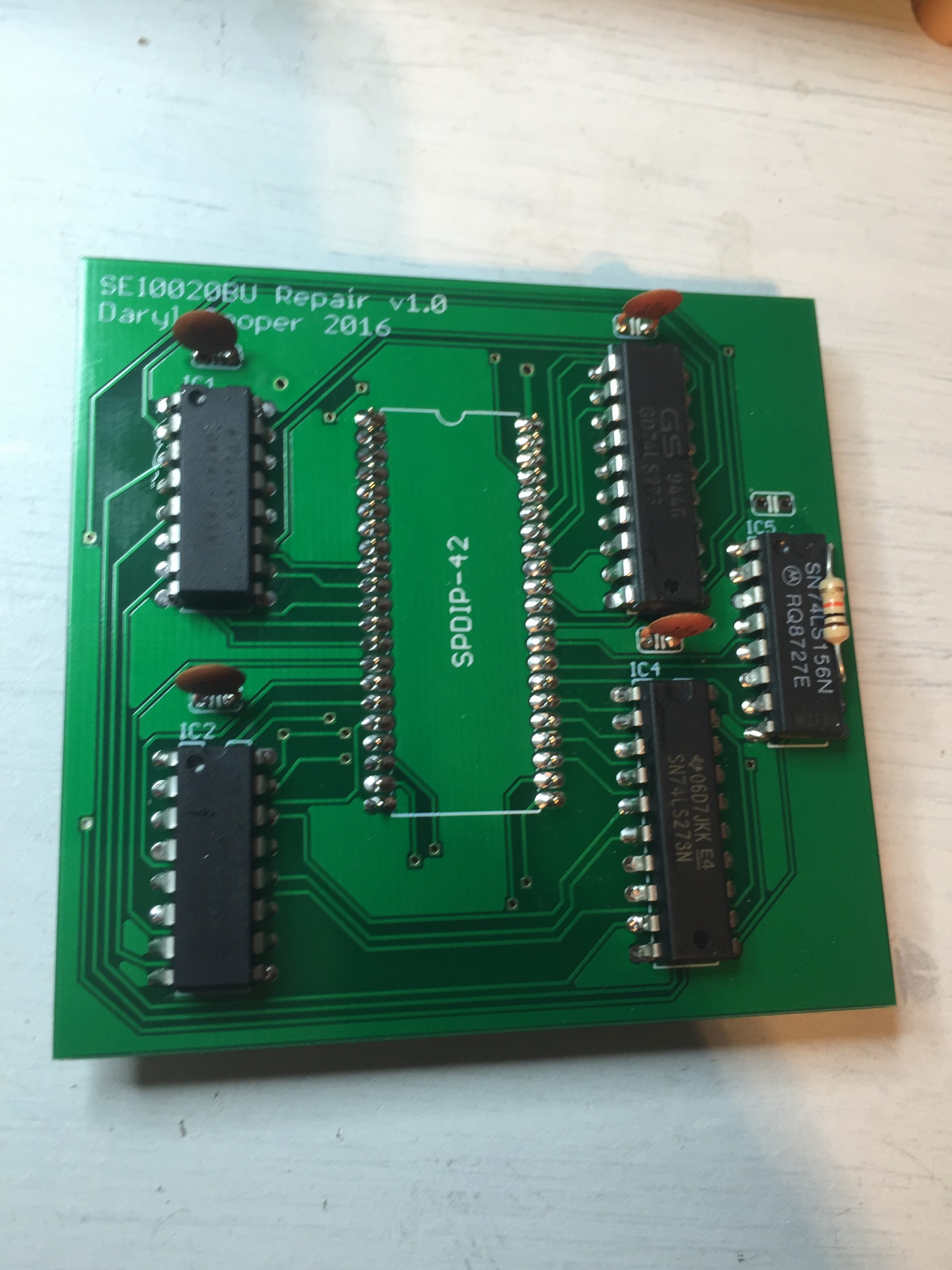
First SEI0020BU daughter board
Once the printed PCBs were delivered, they seemd to work well, but I’d made a few mistakes. Firstly, the output from the LS156 should have been pulled high. Secondly, only 8 bits for the shift offset was insufficient – I actually needed 9 bits. This was a stupid mistake – I’d been unable to test the full shift range properly on my test rig because of a faulty joystick adaptor! Once I tested the board in a cabinet, it was clear that scrolling too far to the left (offset register wraps) causes the tiles to distort (-1 wrapped to 255 instead of 511).
I managed to hack a fix onto the PCB by piggy backing an extra 8-bit buffer and a 4-bit adder onto the PCB, cutting a trace and wiring up with patch wires. The modified PCB finally worked properly, and the graphics were fixed. I wasn’t happy with it though – I’d printed a PCB, so I thought I may as well finish the job!
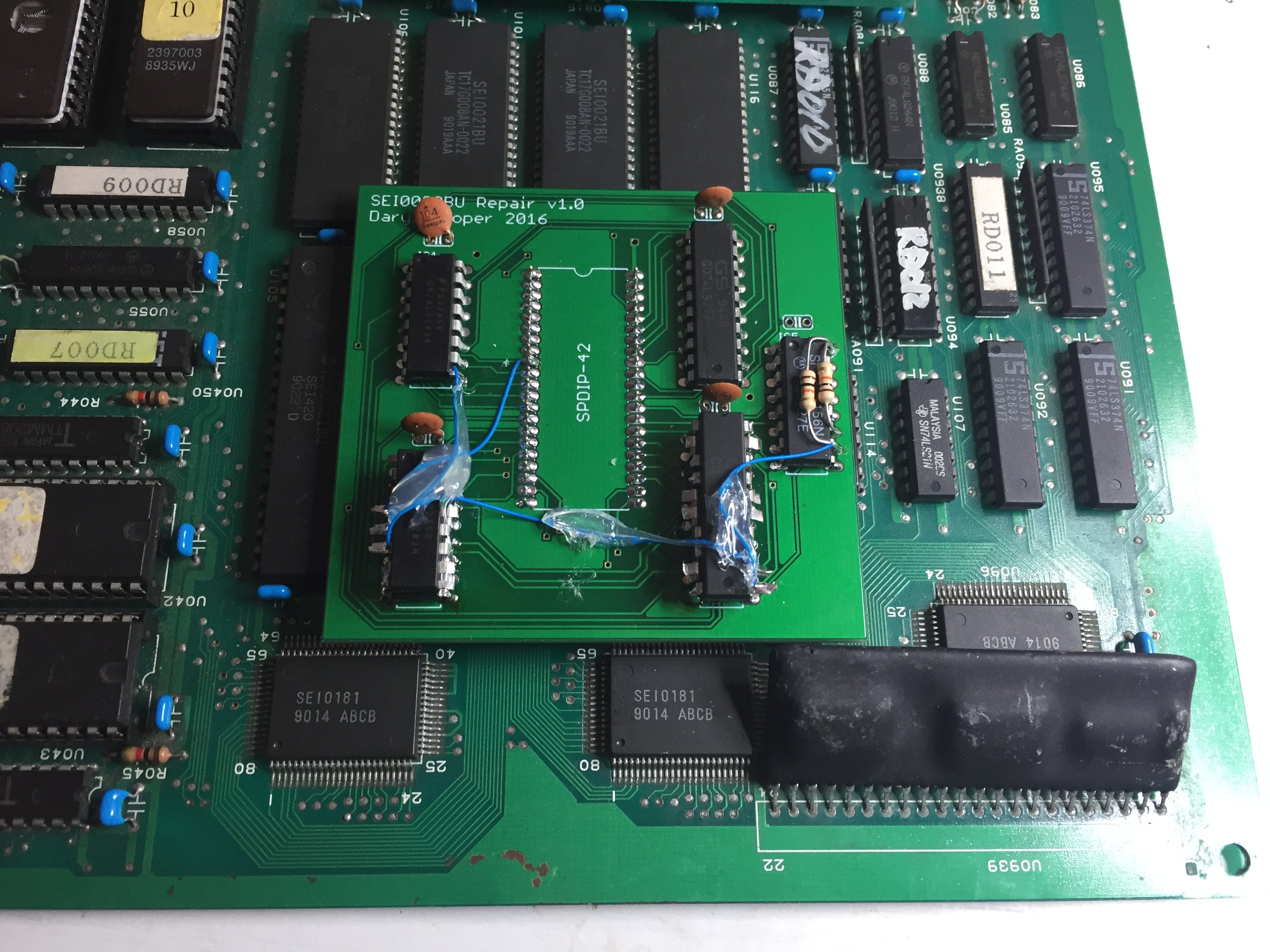
Patched SEI0020BU replacement daughterboard
I modified my design in Eagle (see schematic below), and ordered a new set of PCBs to be printed.
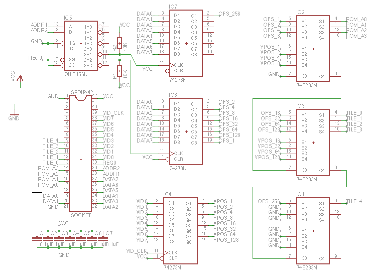
Schematic for Raiden SEI0020BU replacement
The new PCBs arrived, and worked perfectly – phew!
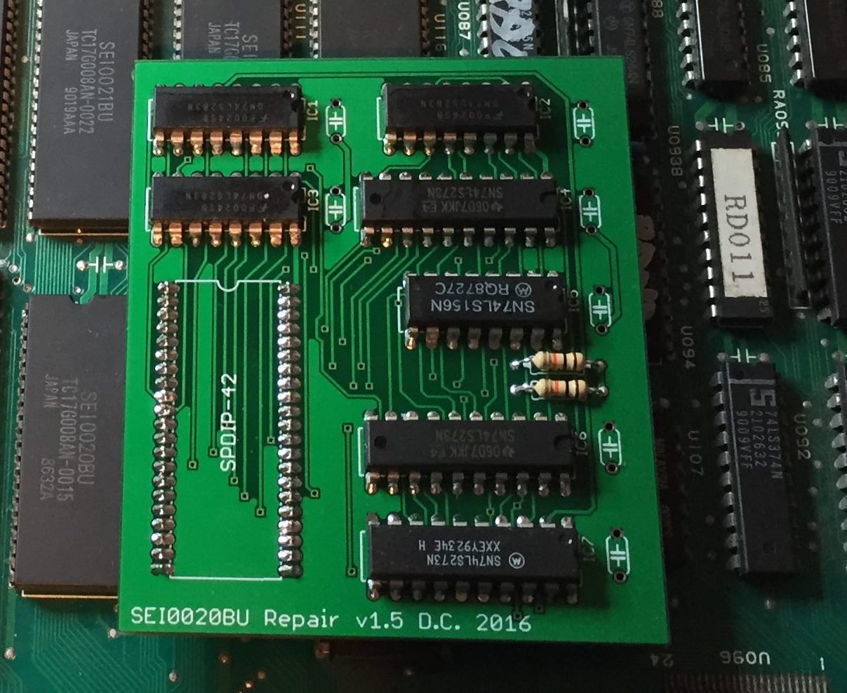
Final working SEI0020BU replacement daughterboard
Sound Fix
Sound was working, but distorted and noisy. Probing the sound input to the amplifier with an oscillioscope showed that the signal was weak. This was driven by the HB-41 SIL package. The inputs to the HB-41 looked clean, so it looked like it was bad.
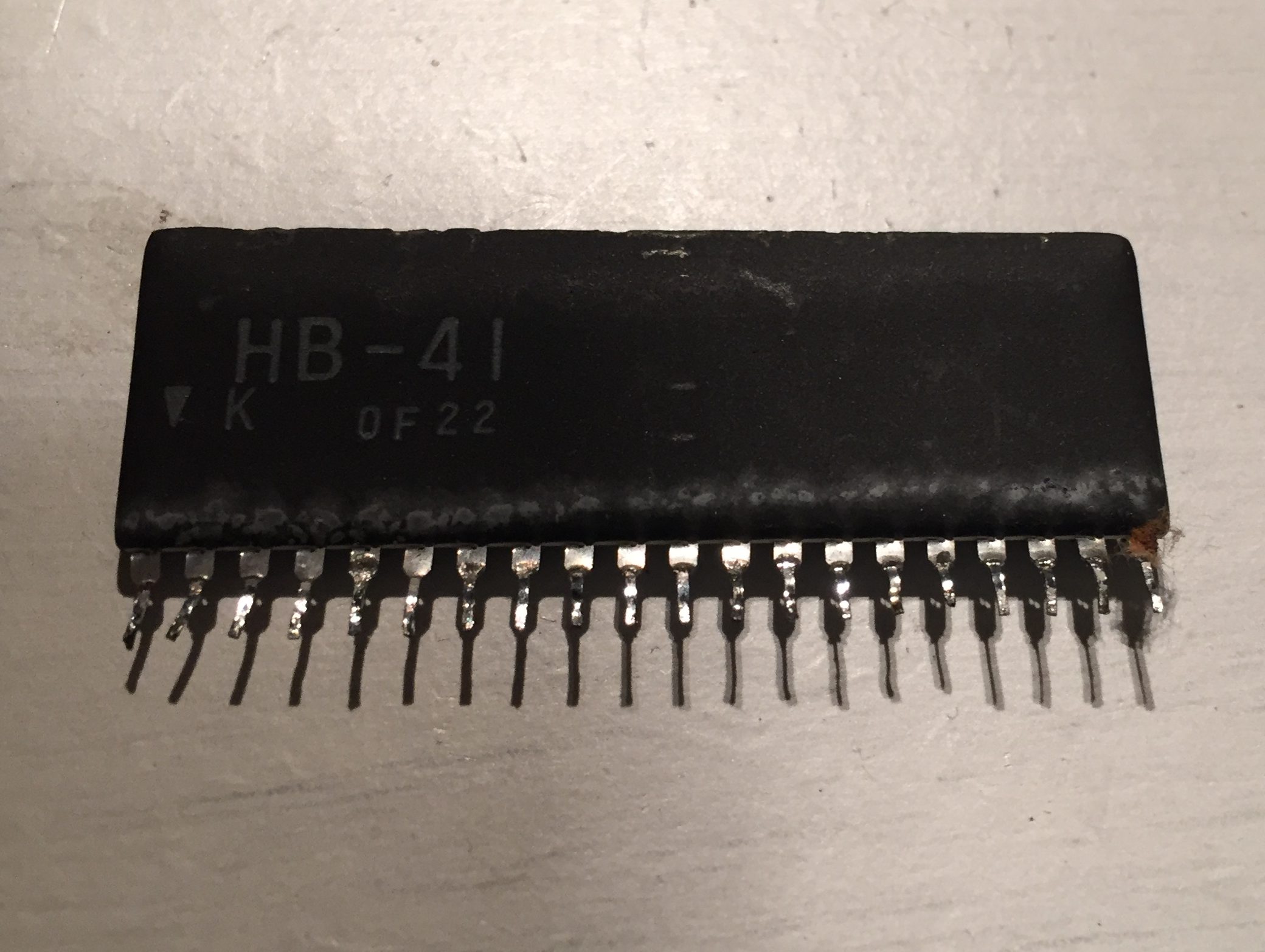
Faulty HB-41 SIL package
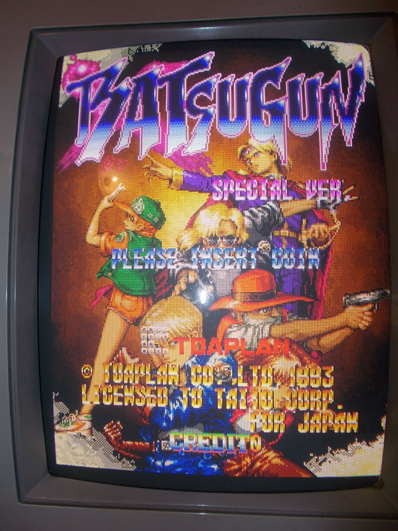
Luckily I had a spare on a Seibu Soccer donor board. Hooking it up solved the sound problem. Job done!
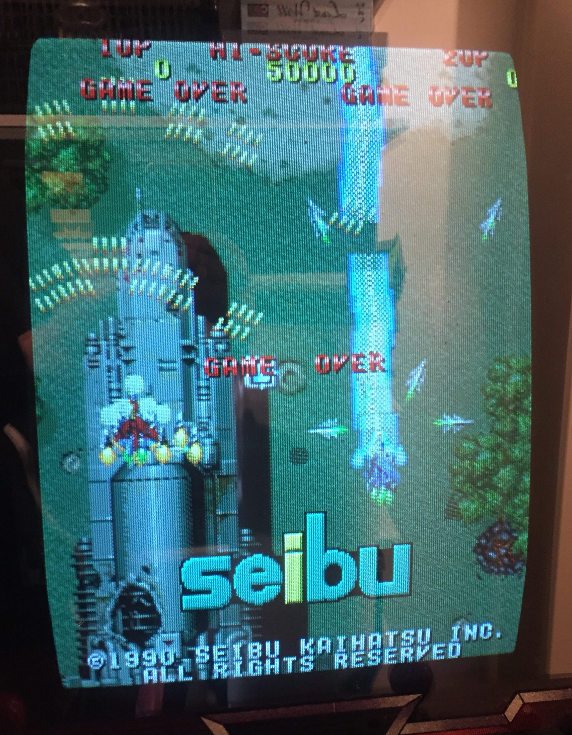
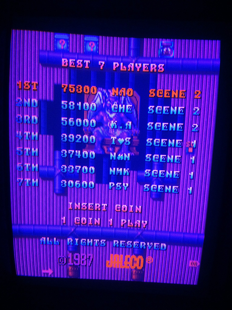
Image is clean, and game now functions correctly. Colour correct in arcade cabinet.