I received a very nice condition Gradius II: Gofer no Yabou pcb from my good friend Robotype. It was sold to me as faulty, described as “the drums are missing from the audio”. The game showed up, and YUP, the drums are certainly missing!
This was an ESPECIALLY odd fault. In my experience, the Background Music and Samples either work or they do not work. I have never seen working, but instruments missing! I started with the logical audio failure points… YM2151 FM synthesizer (tested OK), YM3012 Digital Analogue converter (tested OK) and finally the UPC324 Op Amps (also tested OK). With all of the major audio failure points checking out OK, I decided it was time to try a more aggressive strategy. I turned to the mame source, and determined Konami Custom ‘007232’ is responsible for audio generation. This seemed like a good starting point… luckily for me, my scrap X-Men PCB had this IC present. Time to remove and swap the IC!

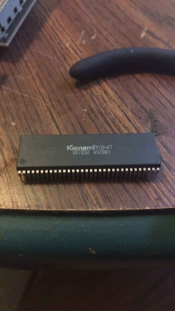
SUCCESS! The newly fitted ‘007232’ custom Konami Audio IC did the trick, the drum line is fully restored and the BGM is back in all of its awesome glory. Job done!