Feb 042017
 

I got several months ago this really rare game from a laserdisc collector for a repair. It seems that this game was made a few units and many of them very found in Italy .

This collector infact has another fully working unit in an original cab but wanted to repair this pcb as spare part, which came from another original cab but in very rusty conditions.

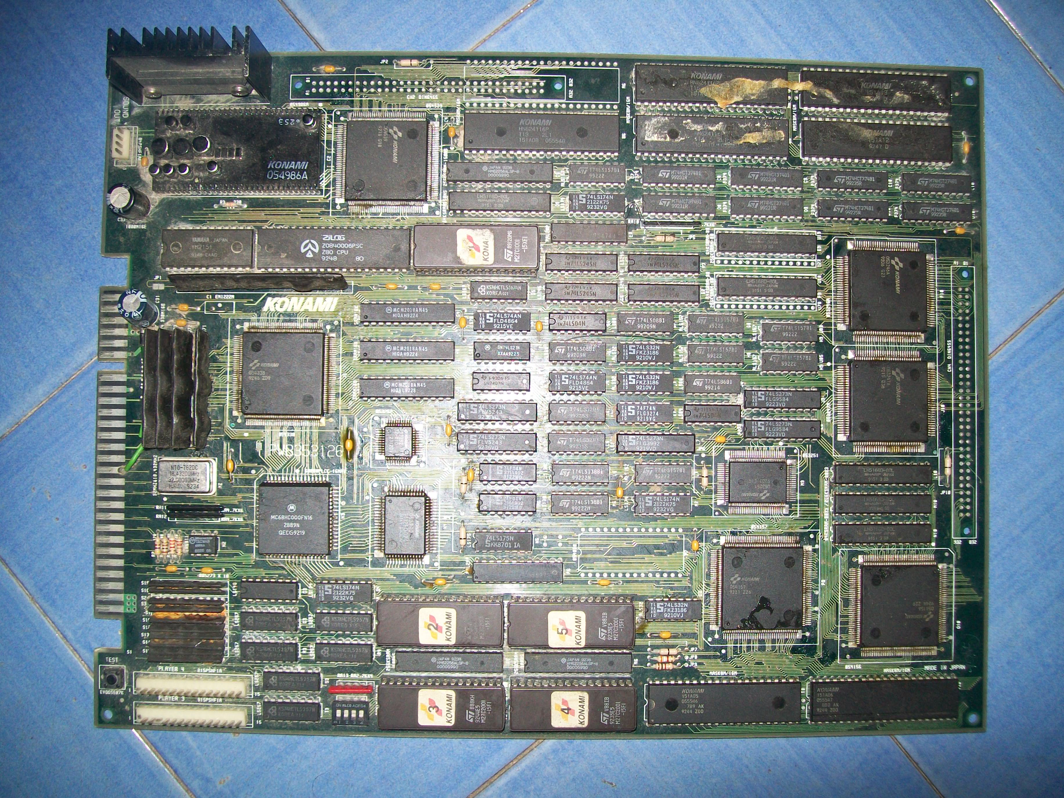
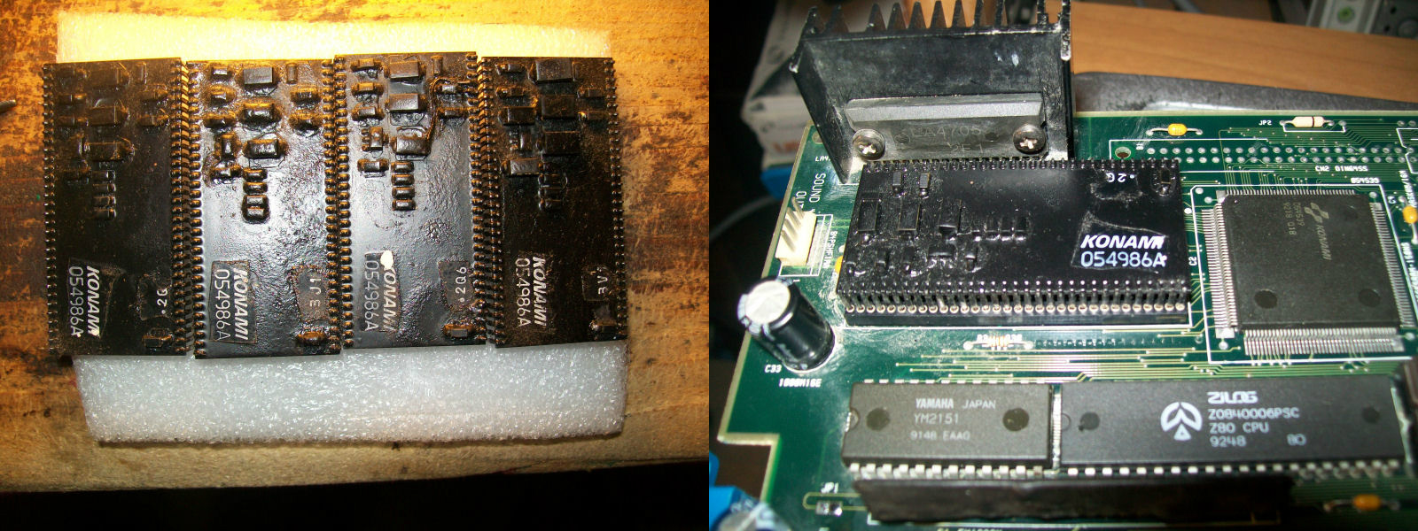
When I received the pcb, many attempts to repair were made, it had a lot of chips already in sockets and jumping wires all around due to the poor soldering skill of the one who attempted the repair.

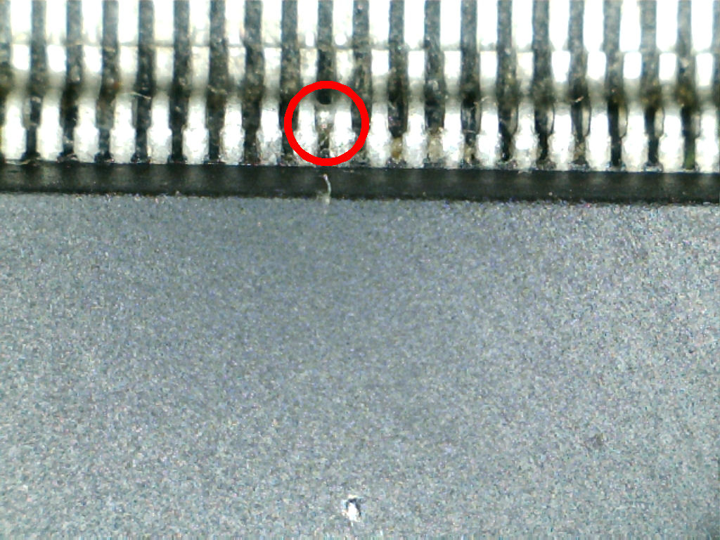
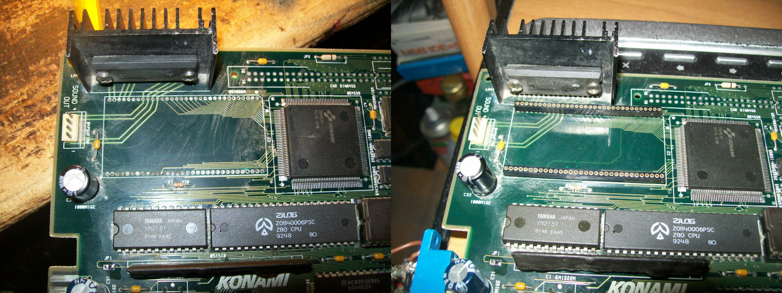
On top of that, the pcb had some overheating (disconnetion between bottom layer and top layer).


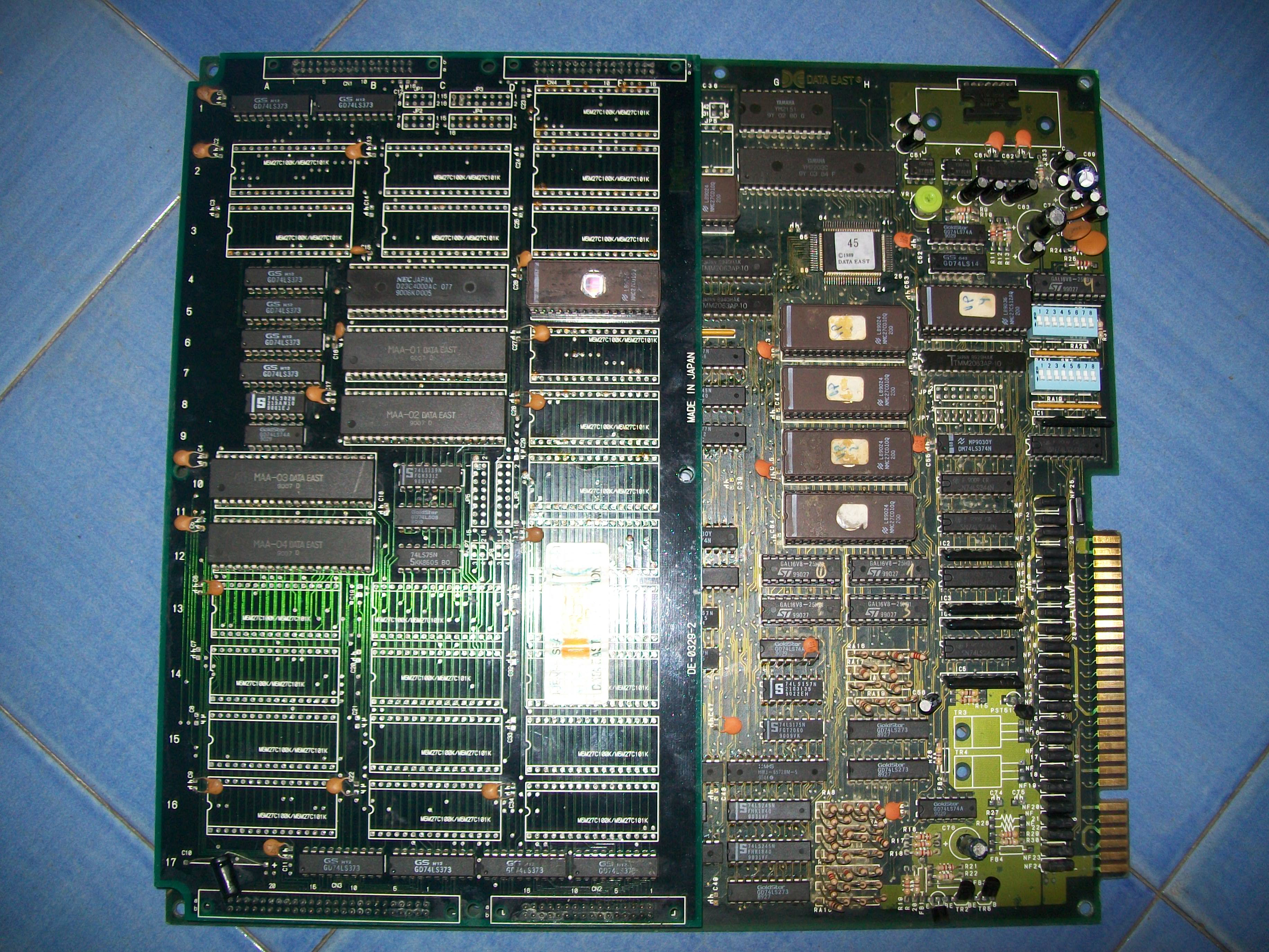
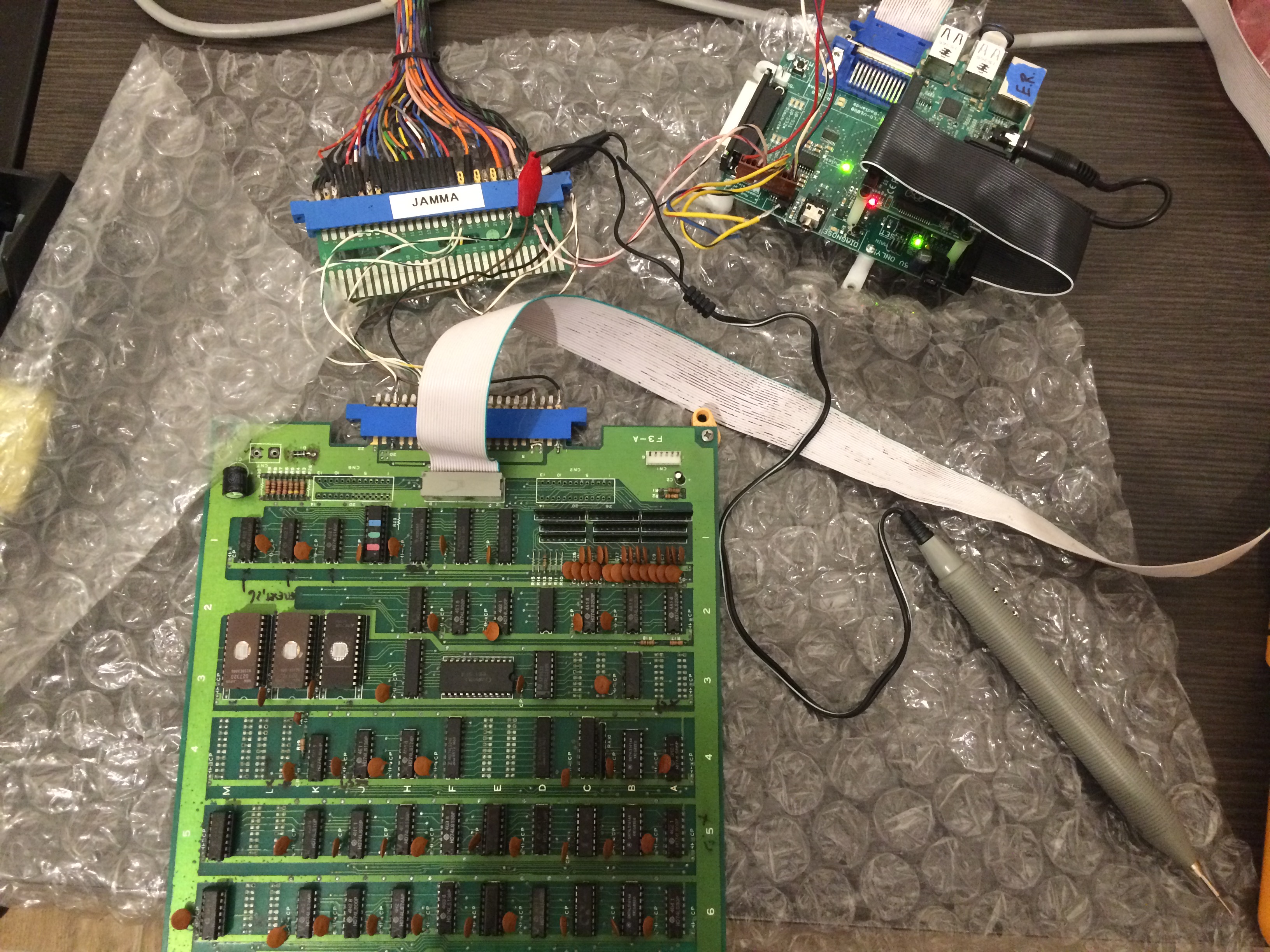
I made a Jamma adapter without any pinout or schematics because this game has no documentation whatsoever.

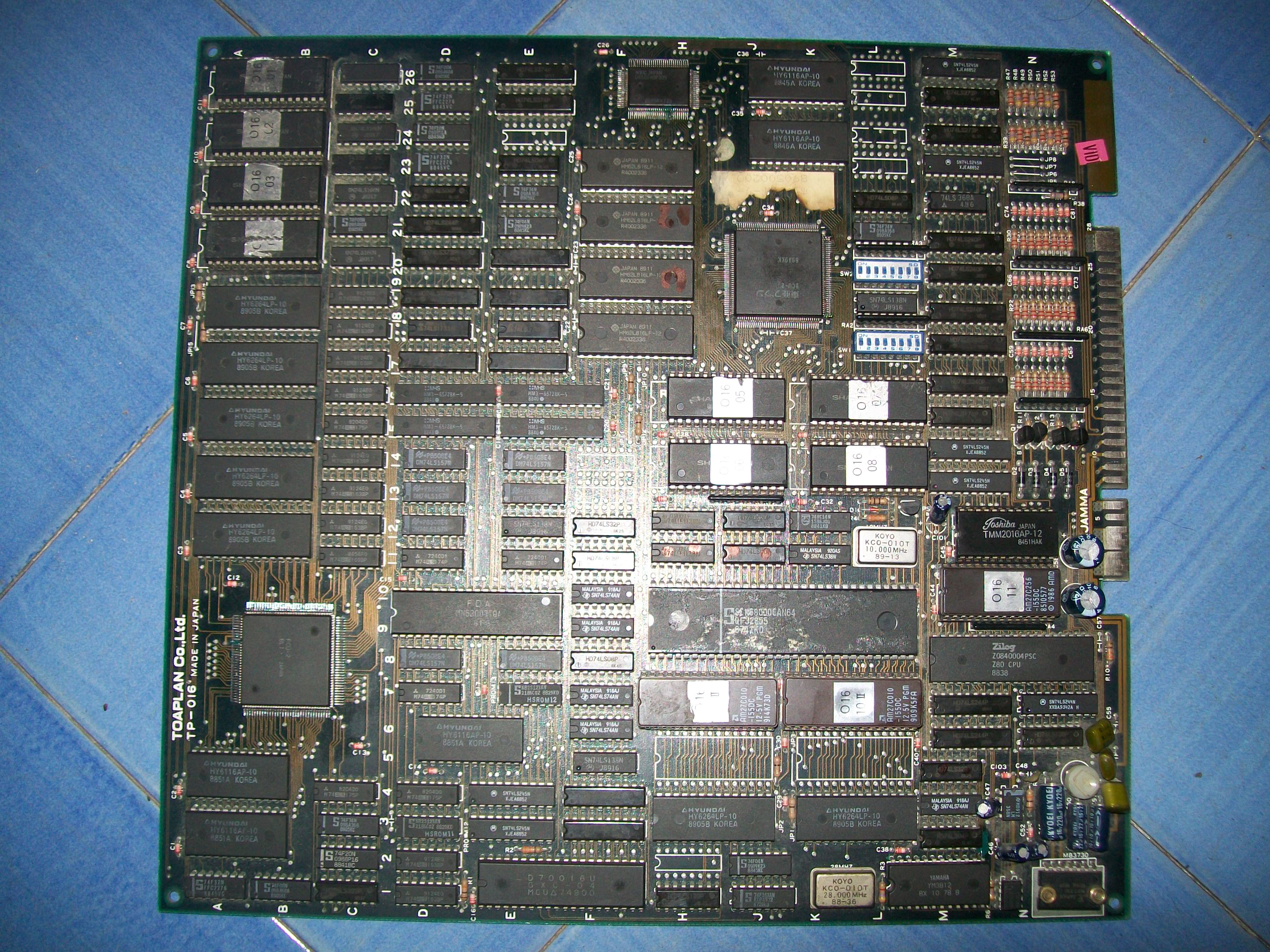
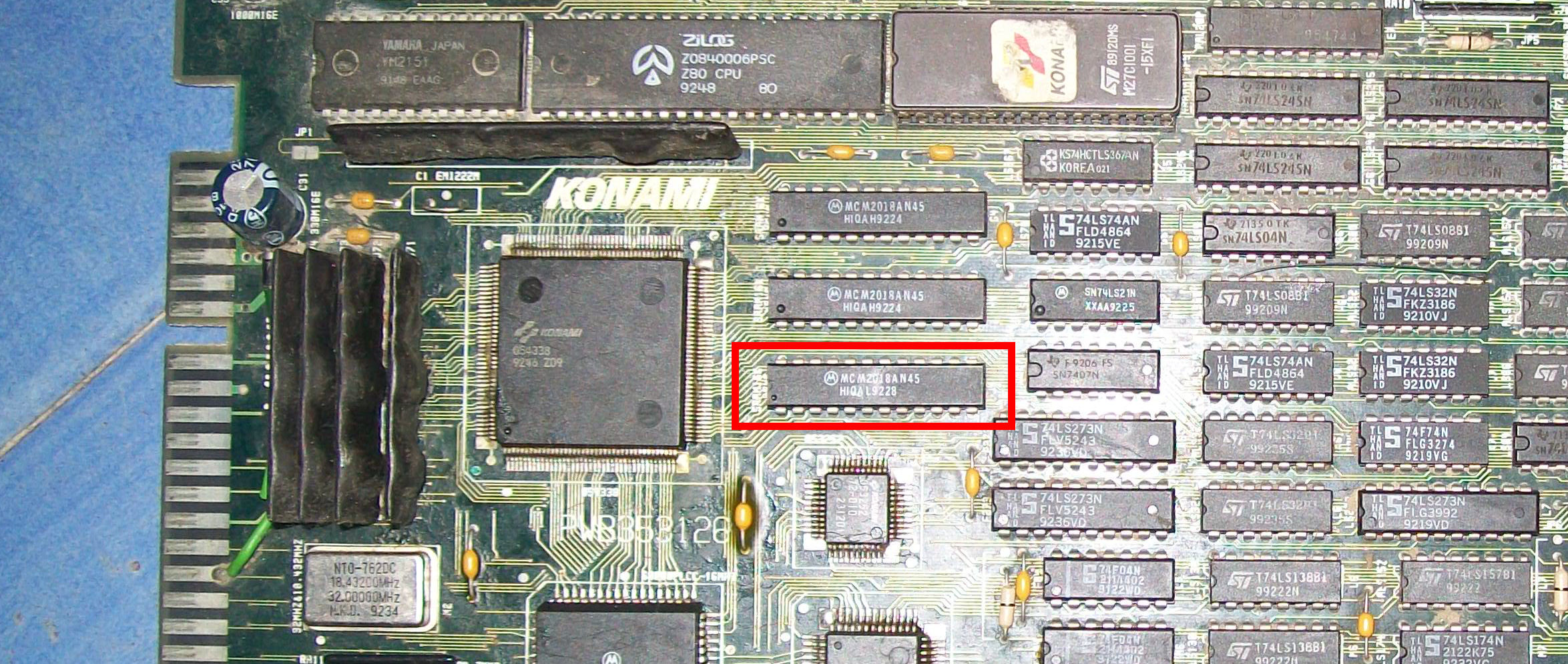
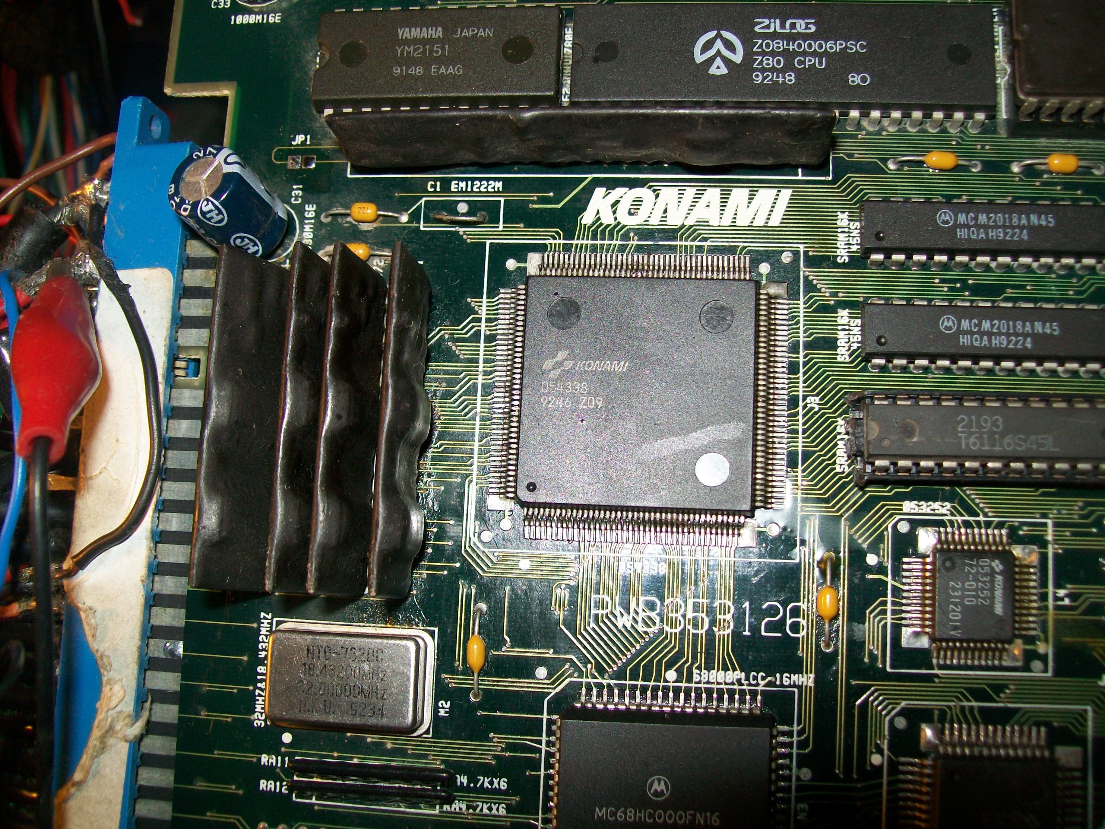
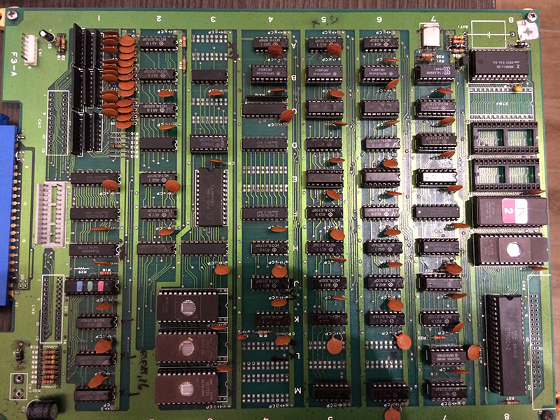
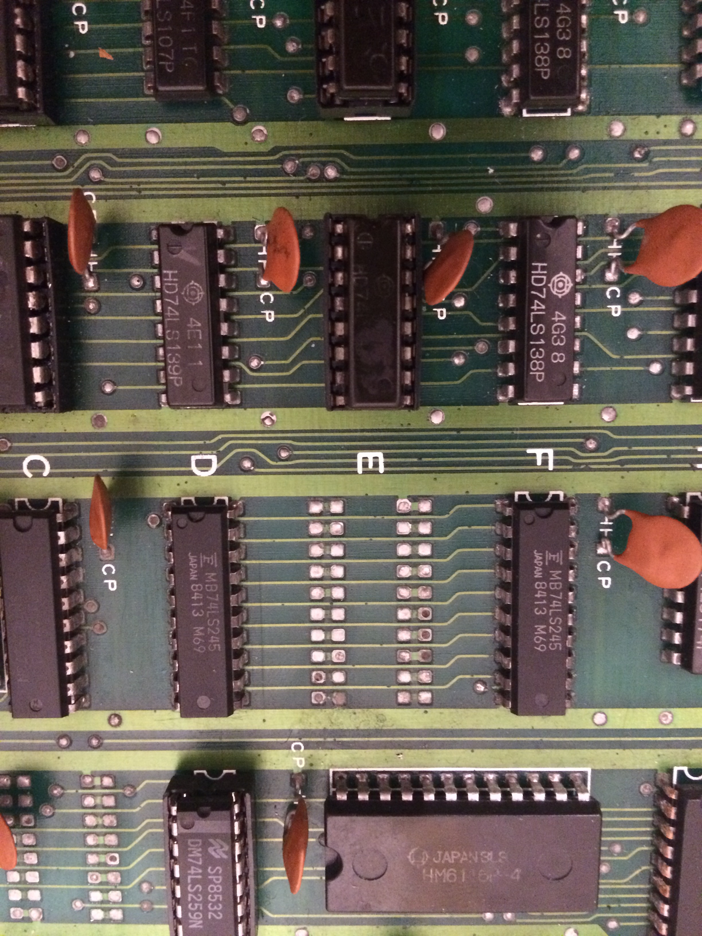
Luckily the pcb design is really simple, with only TTL logic.

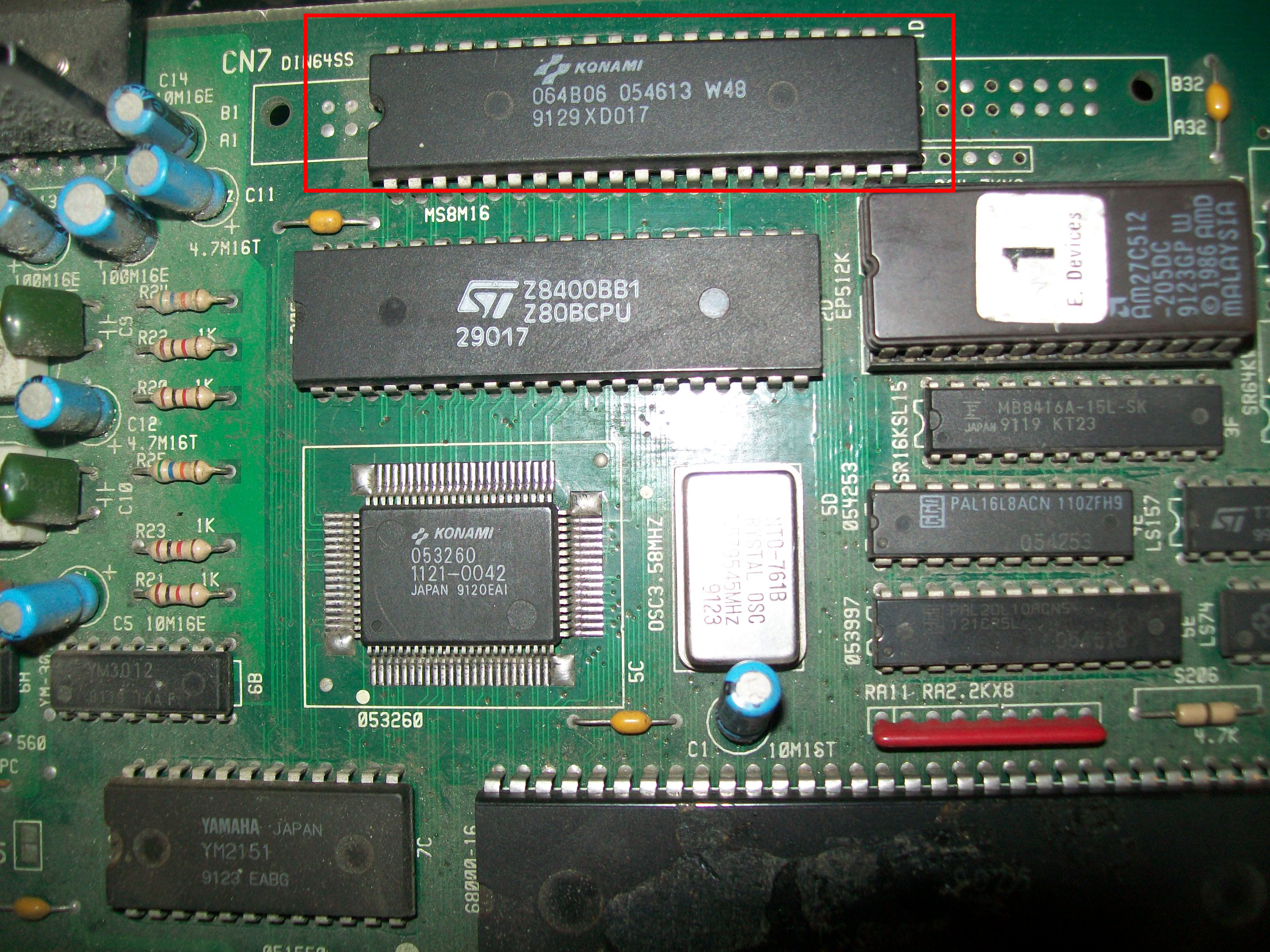
When turned on, the game didn’t even sync with the monitor. Given the fact that the game has only one clock I immediately started my troubleshooting

by looking around that part.

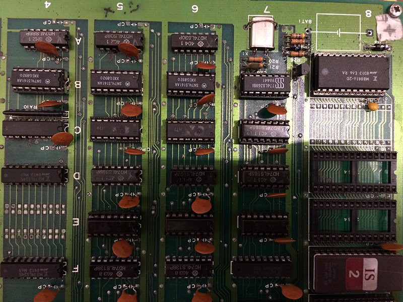
I immediately found out by tracing the circuit that 3x 74LS161 (Fujitsu parts) had lots of output dead.

I procedeed to change all three of them


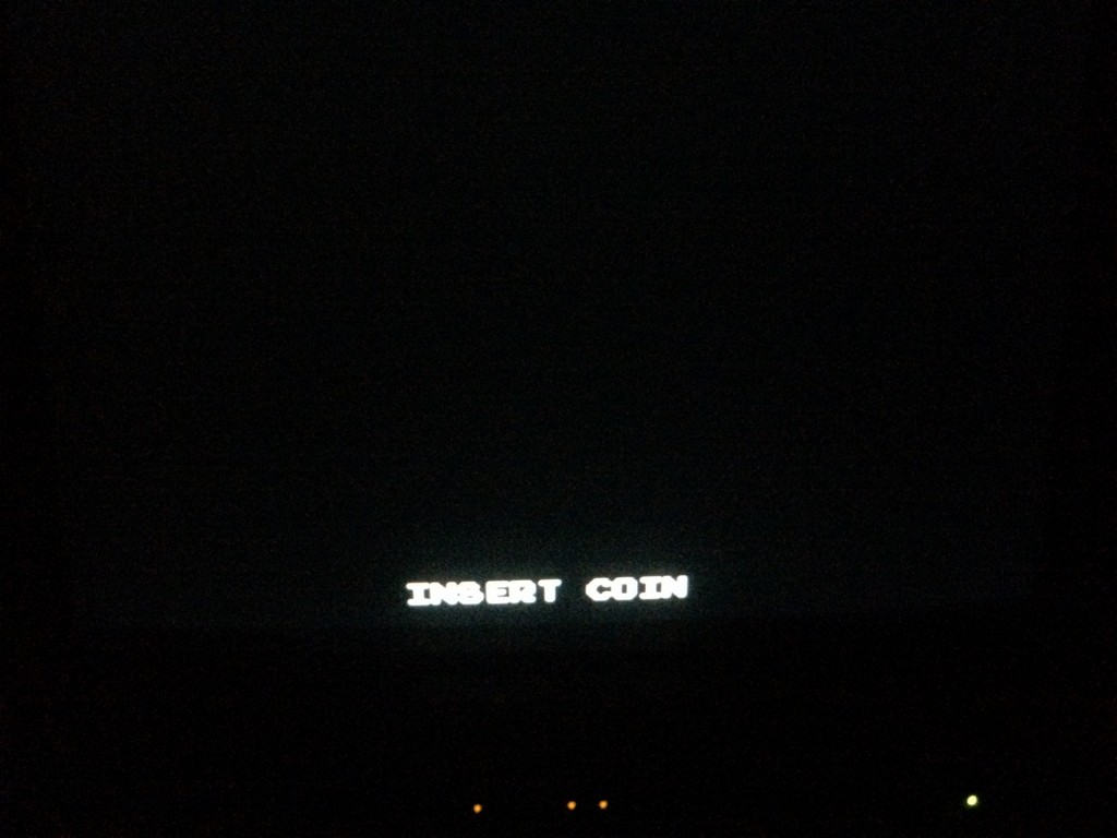
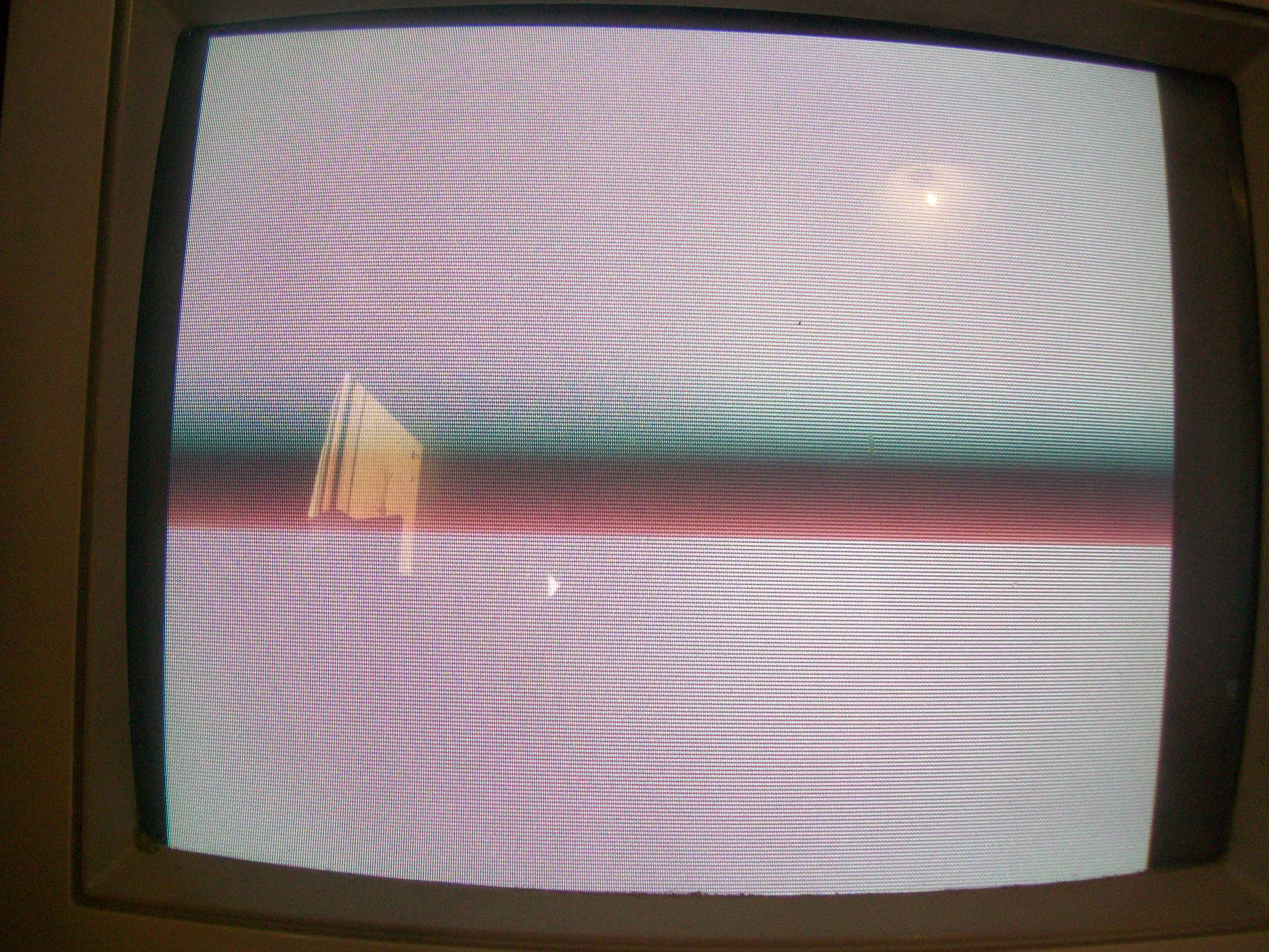
and finally was greeted with some colours


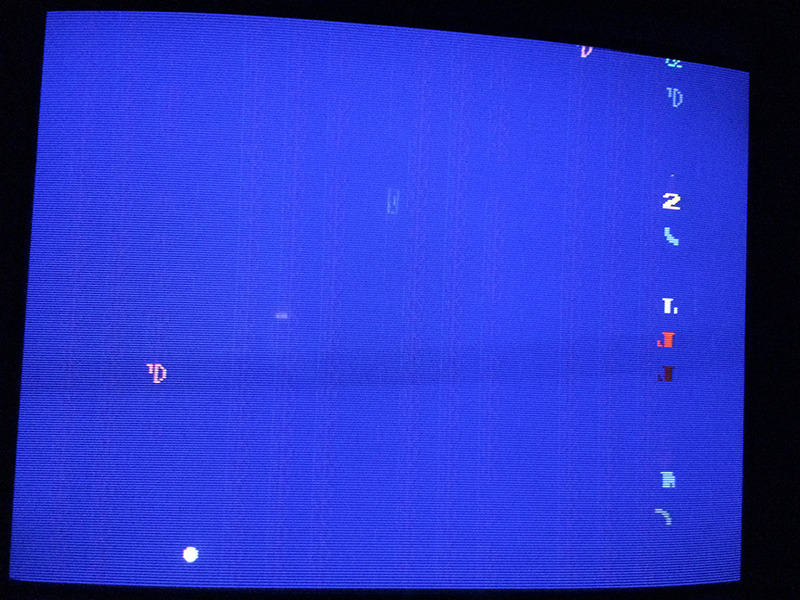
As you can see, the game still didn’t boot and was stuck

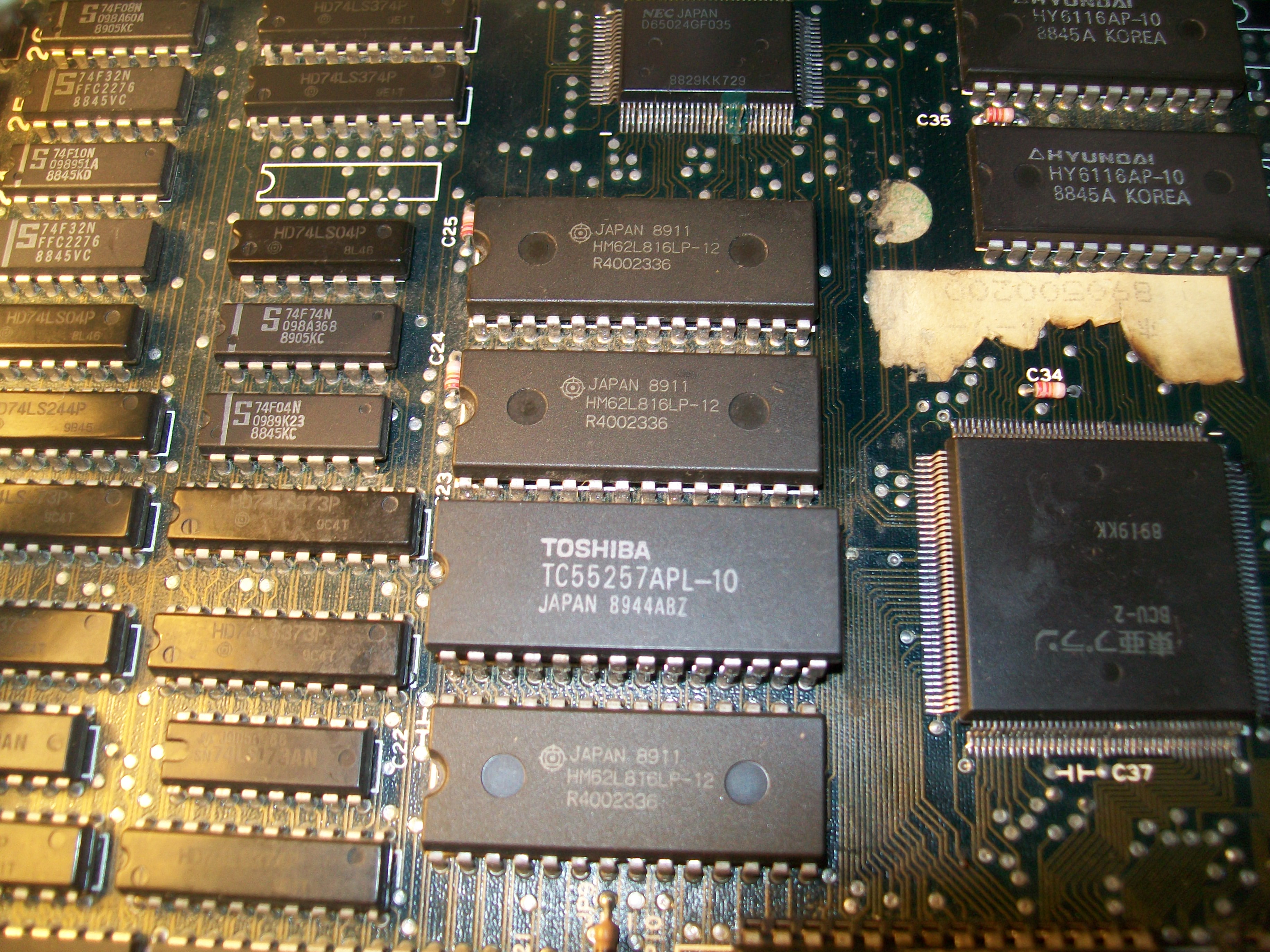
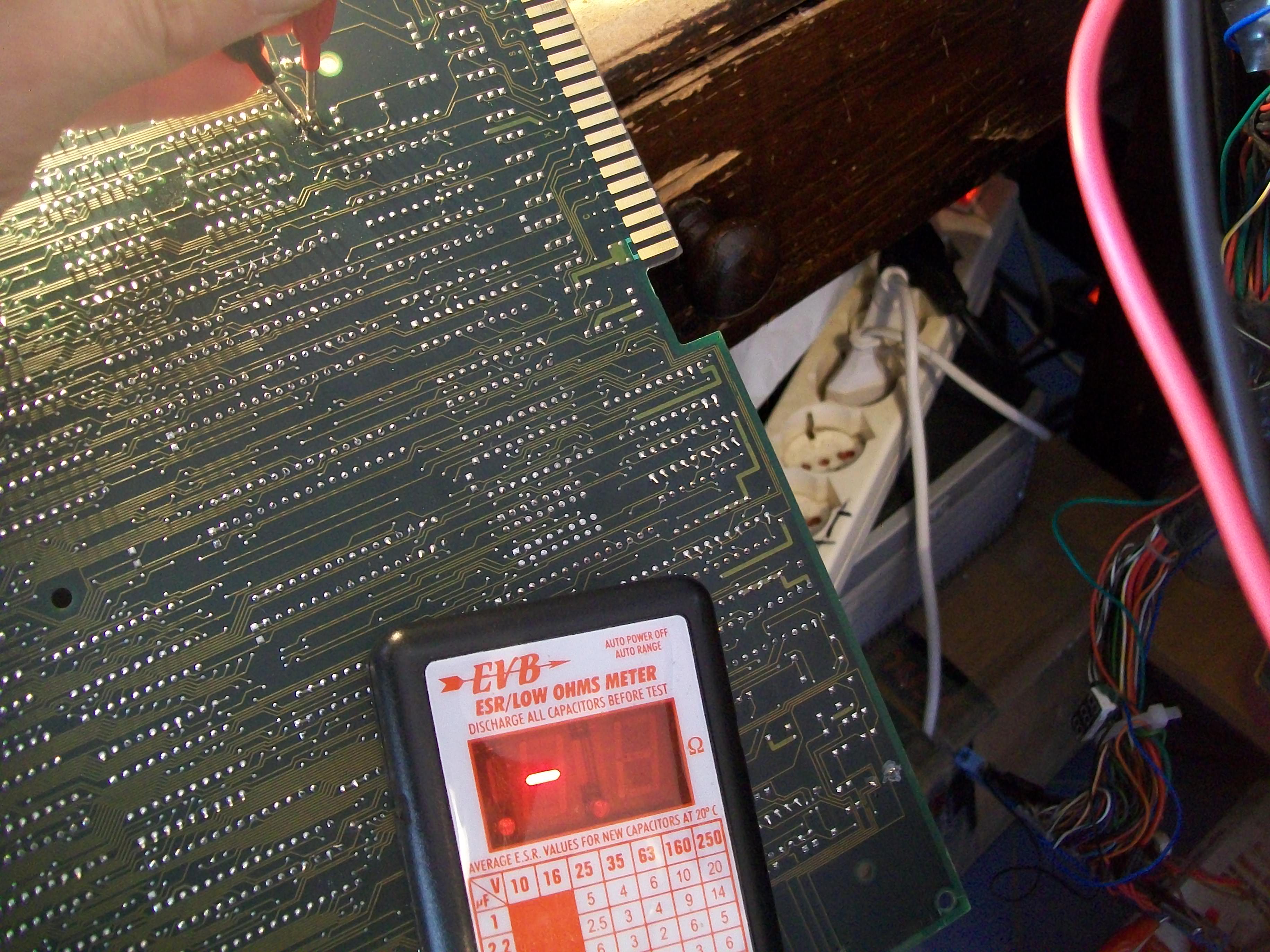
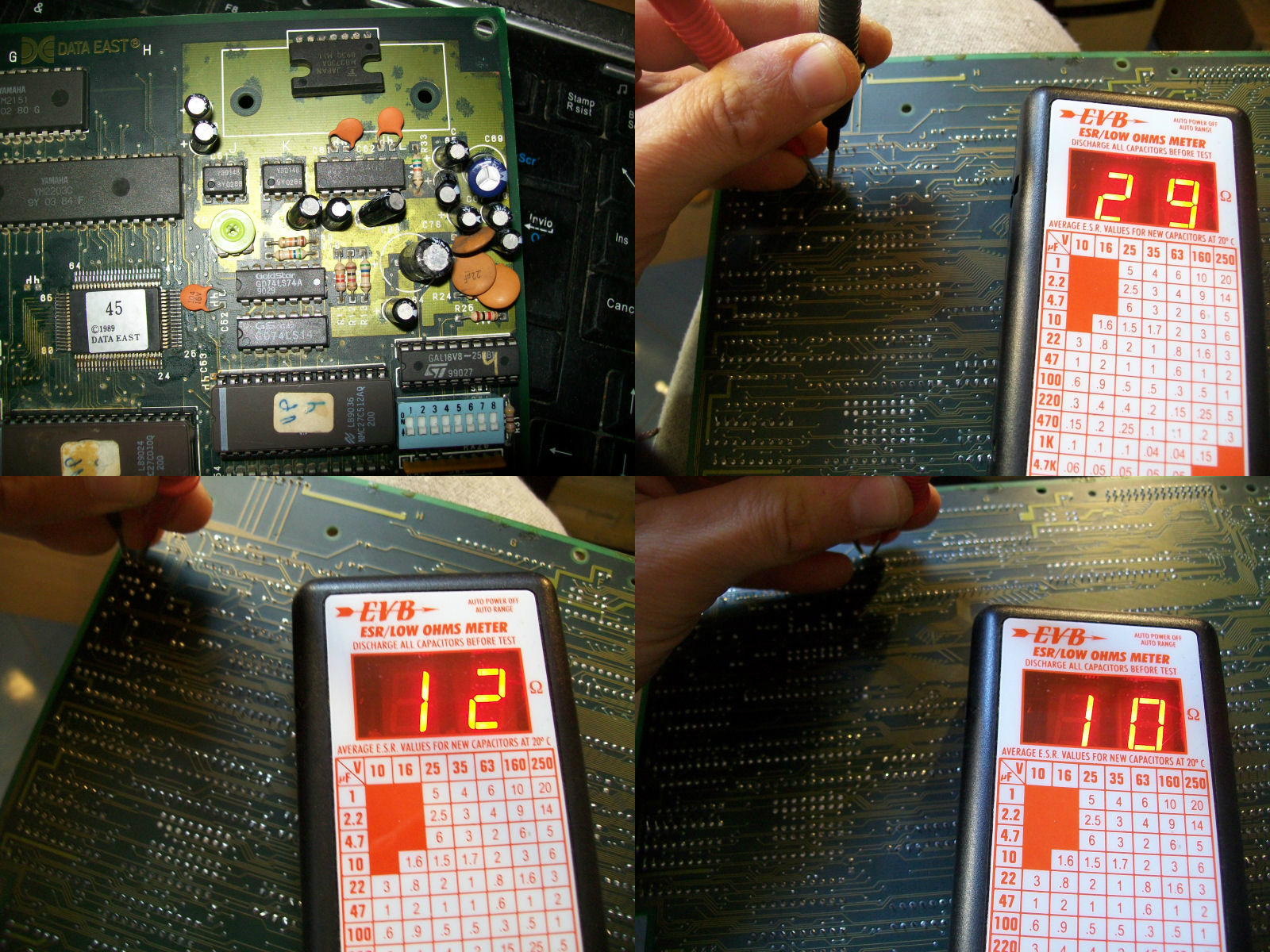
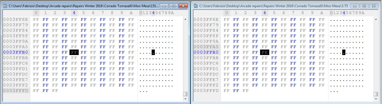
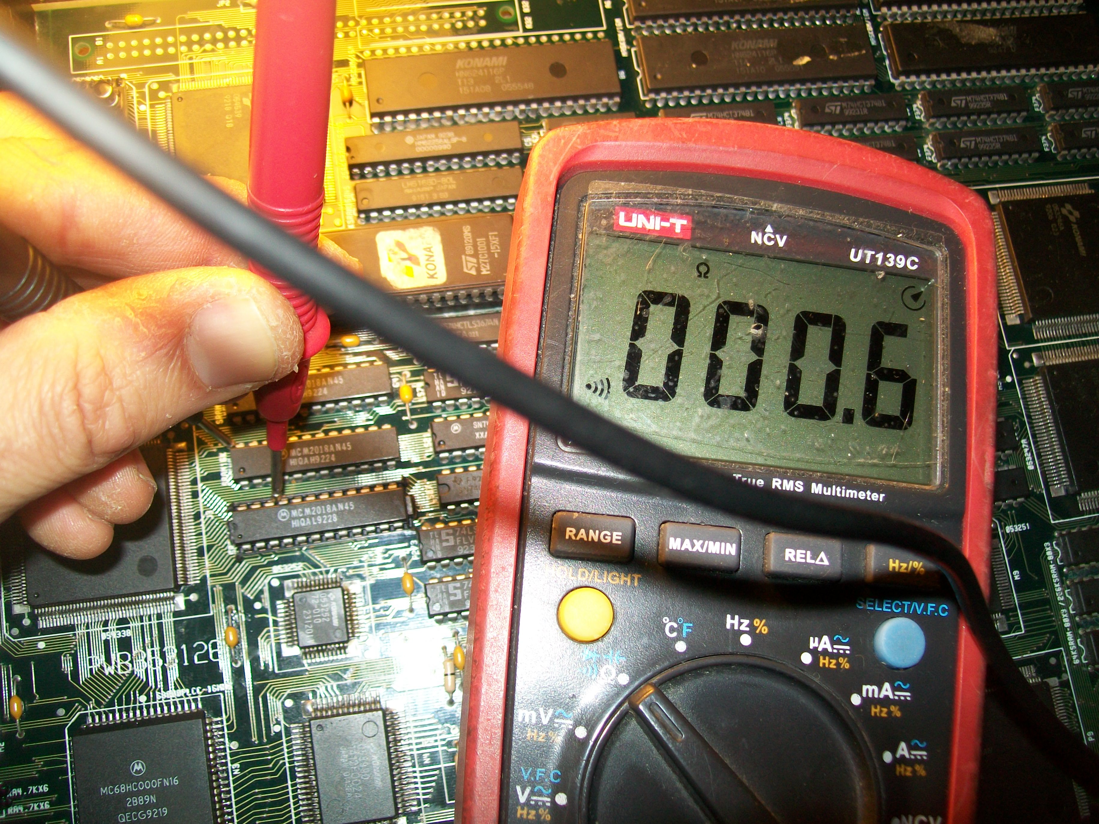
I checked the only program ram on the game (near the battery place) and found out that the data pins were not working.

The strange thing was that the ram was already socketed and was good.

Turned out to be the first of several desasters made by the previous repairer.

He soldered badly the GND pin which apparently was not making contact to the pad, so the ram was not powered.

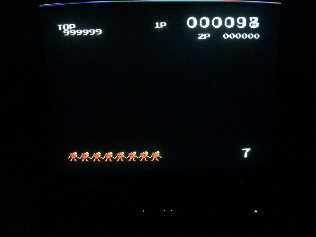
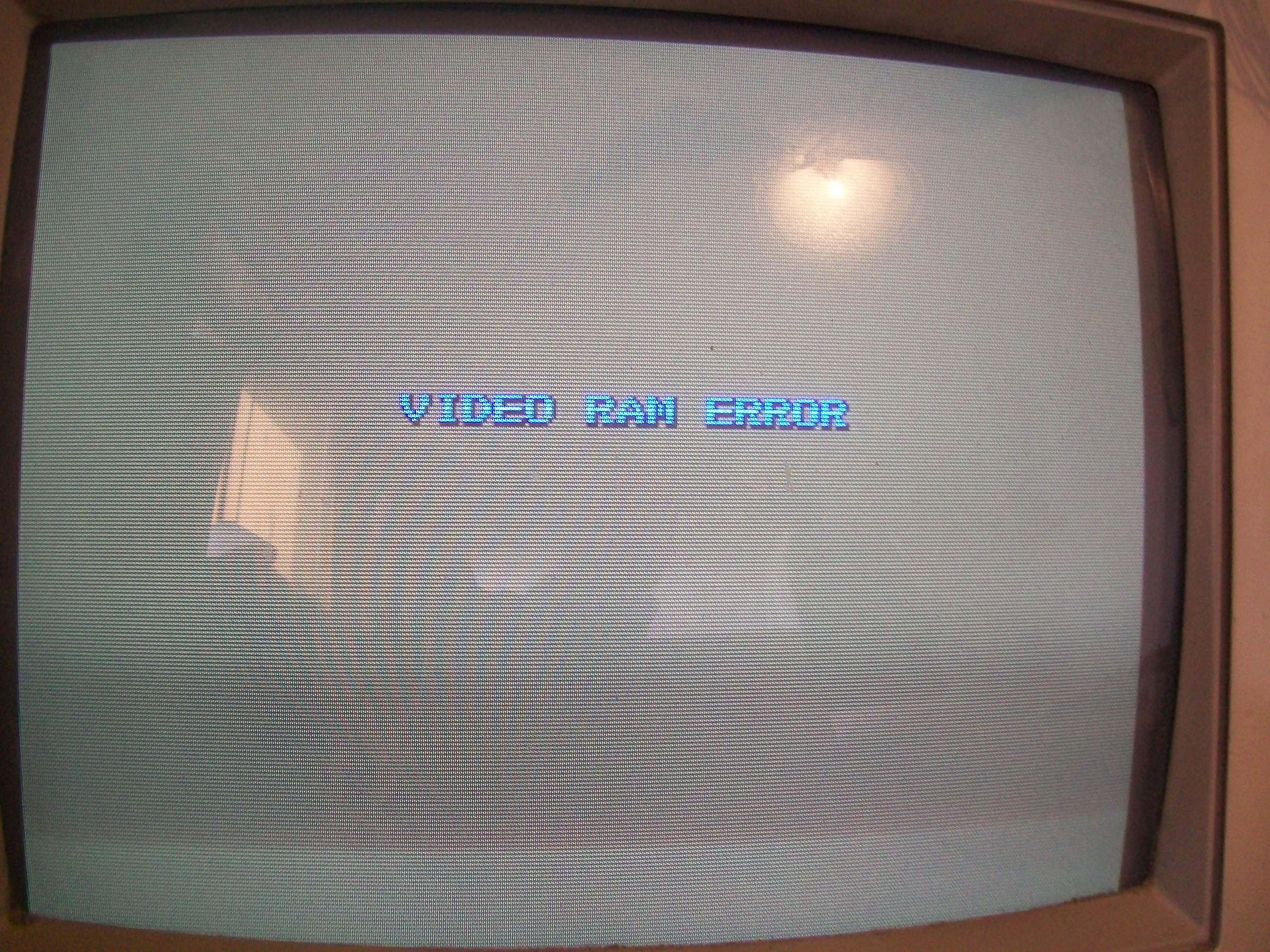
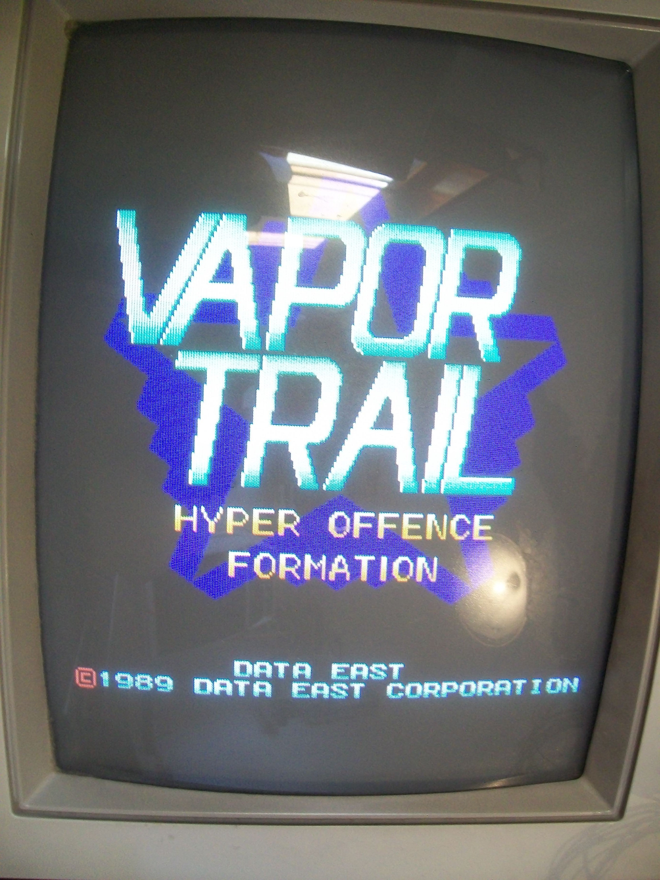
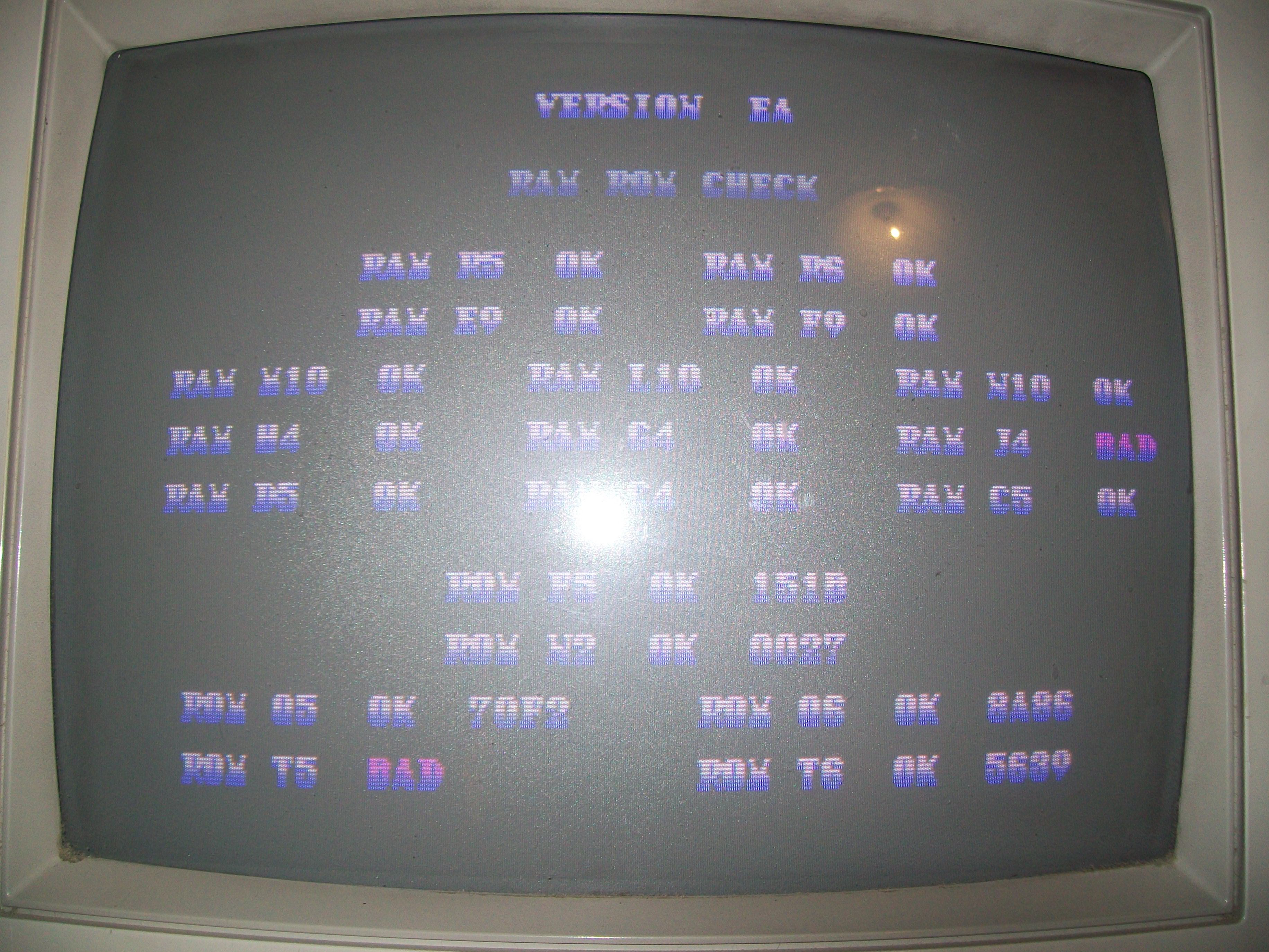
After fixing the issues, I finally was greeted with this image:


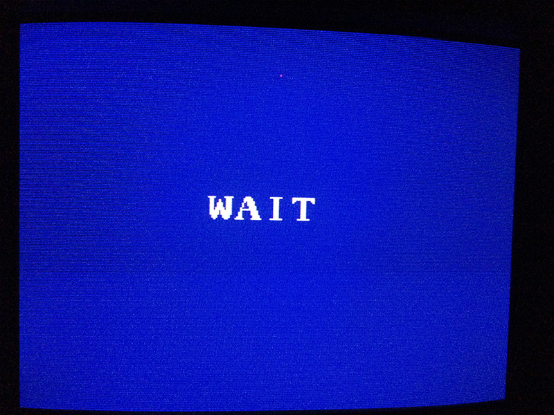
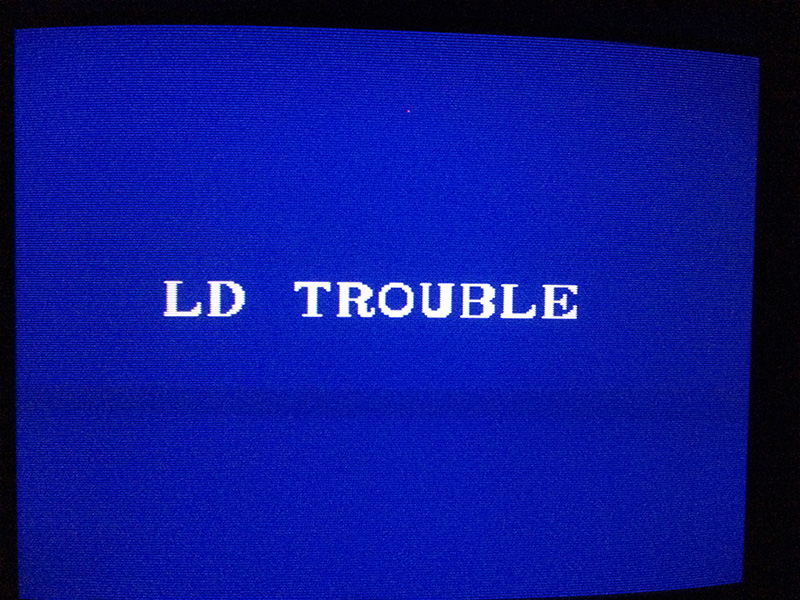
Good news, because it meant the program was running but was not finding the Laserdisc unit

At this point I was quite sure I repaired succesfully the game , so I met the collector at his house and tested the pcb

with the original cab, but the game still didn’t find the laserdisc unit!

Ok, there was something faulty in the serial comunication on the pcb because the cables and laserdisc unit were good since they worked

on the other pcb.

The collector was waiting for a Dexter unit, which is a device which emulates a laserdisc and you can store the movies on a micro SD card.

Therefore we agreed I would wait to have this unit borrowed to continue the trouble shooting.

After 3 months of waiting, the Dexter finally arrived and I resumed the trouble shooting.


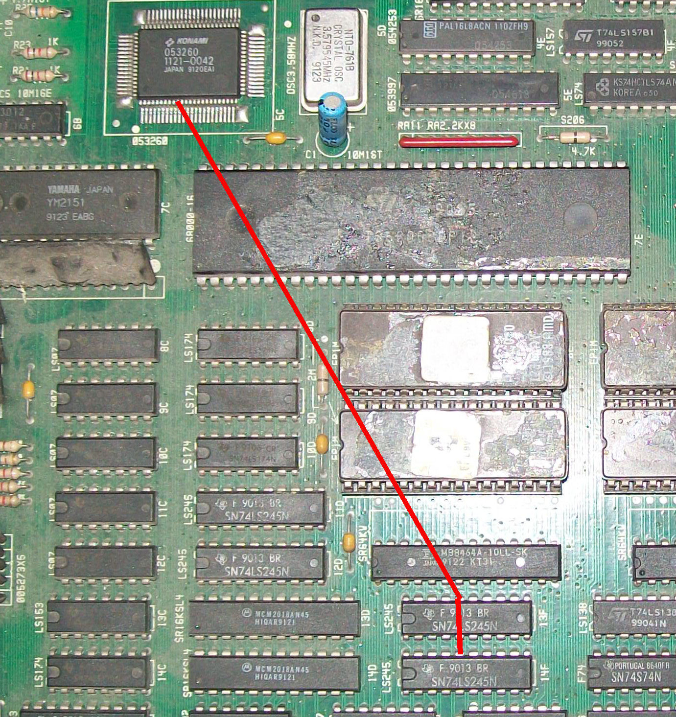
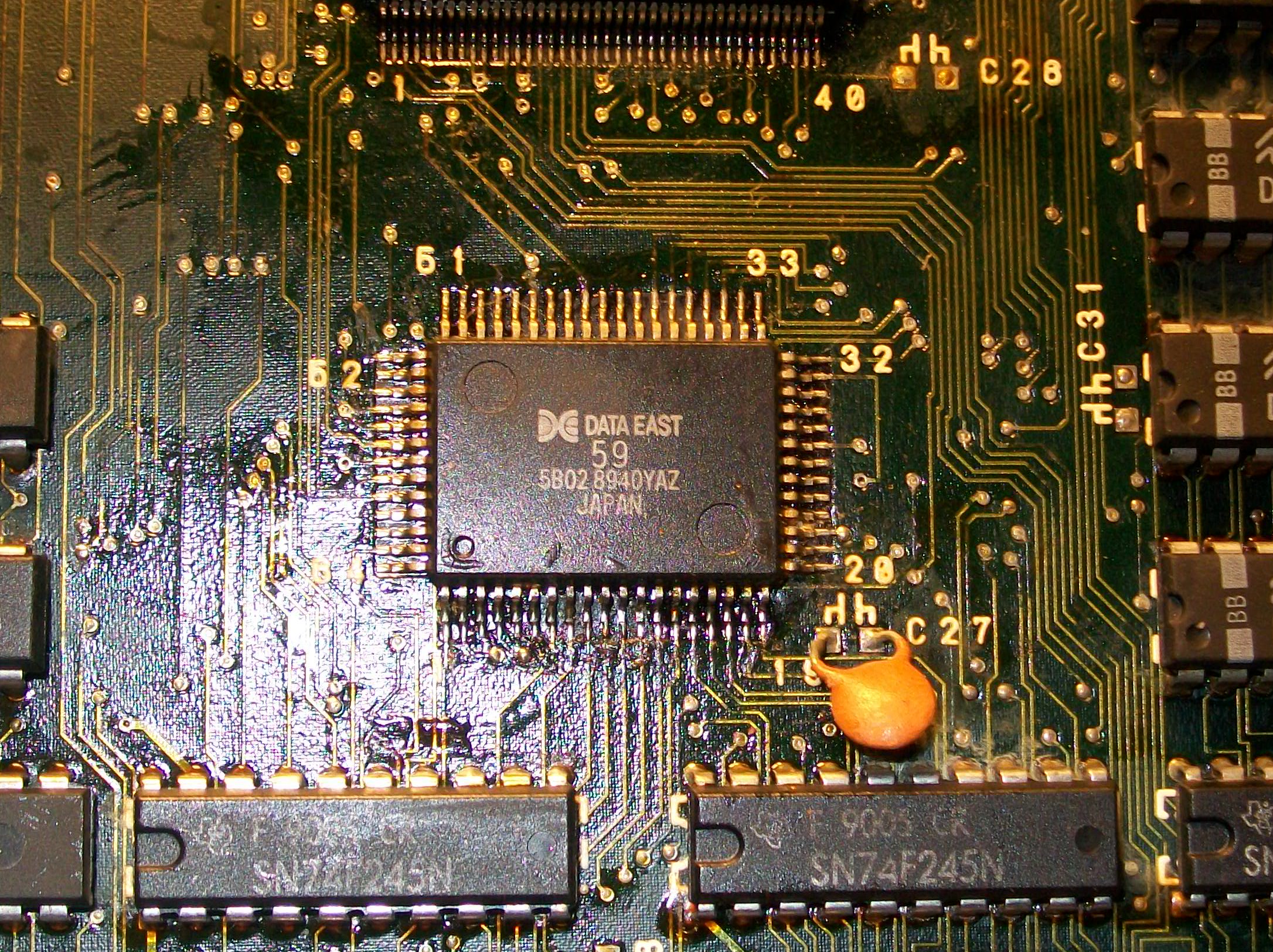
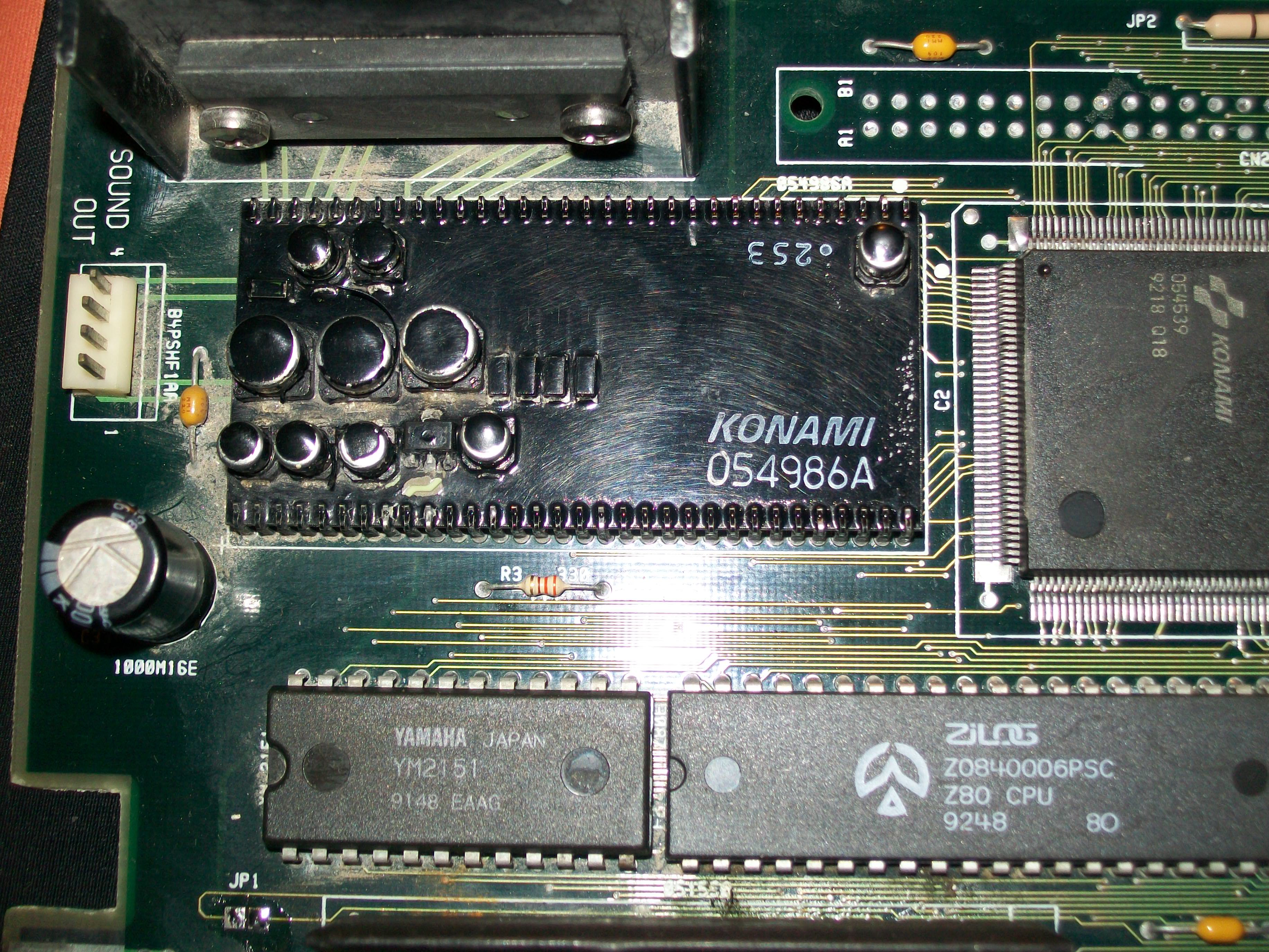
Tracing back the signals from the connector of the laserdisc, I came to a couple of 74ls245 and one of them had the enable pin in the grey area.

I followed the trace back to a 74ls365 which was exhanged previously and guessed what? Bad soldering again!

I melted the bubble of soldering and restored the connection

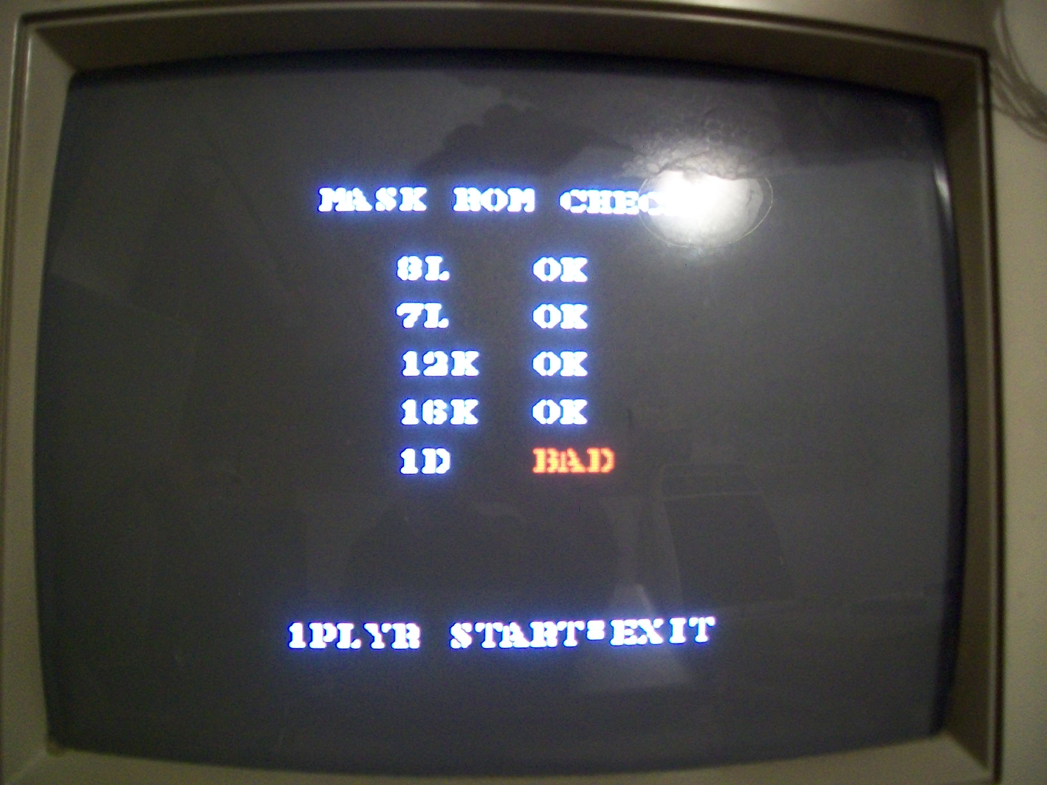
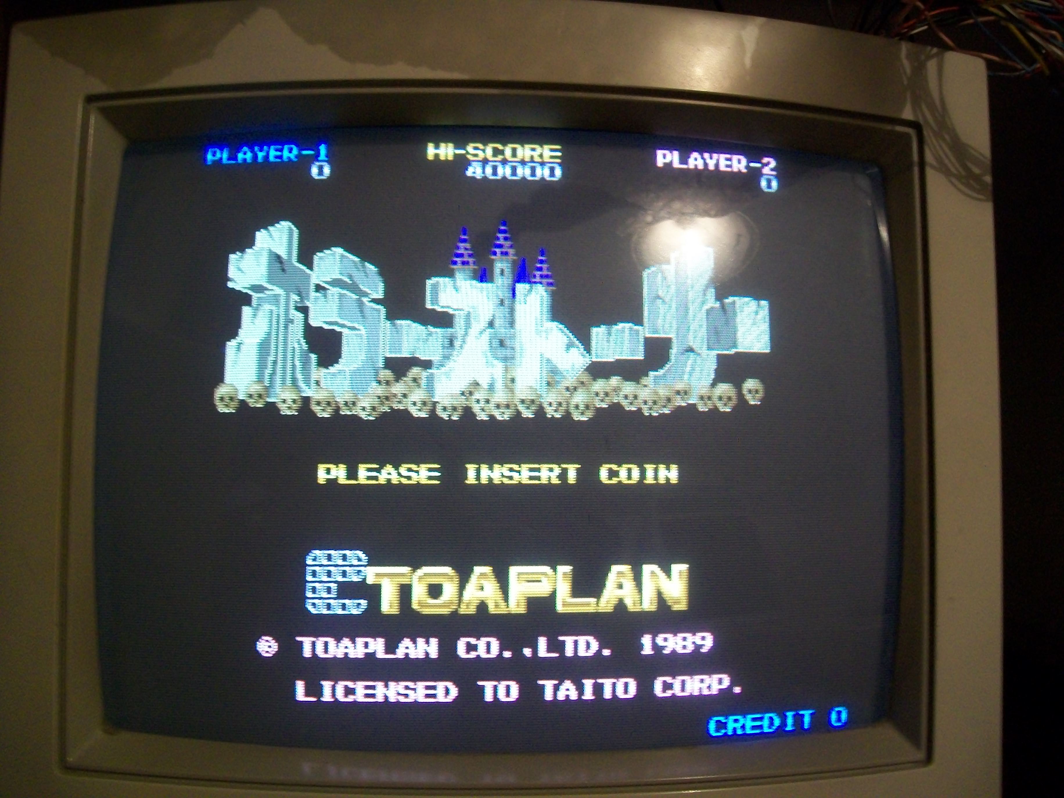
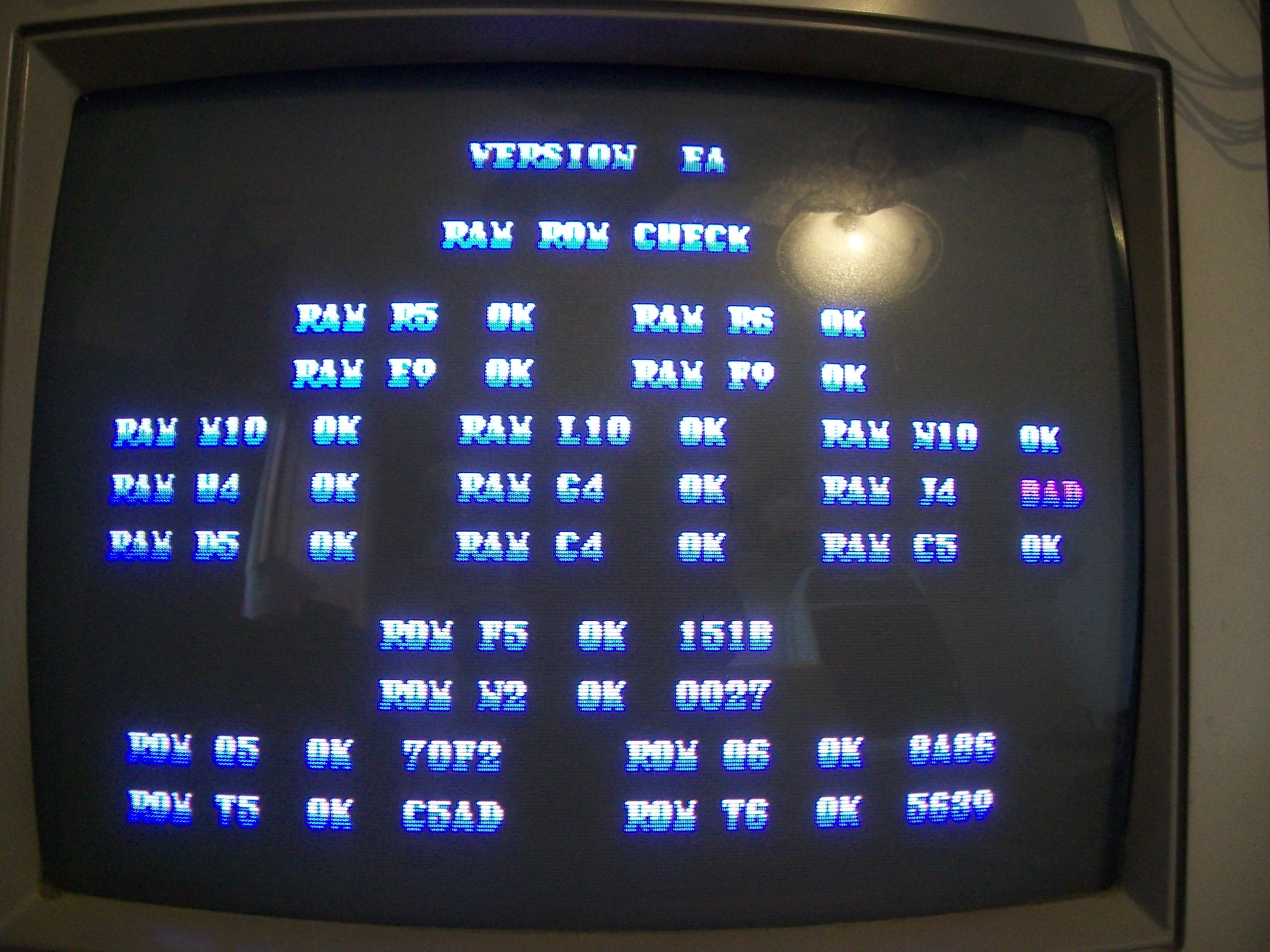
Finally the game booted!

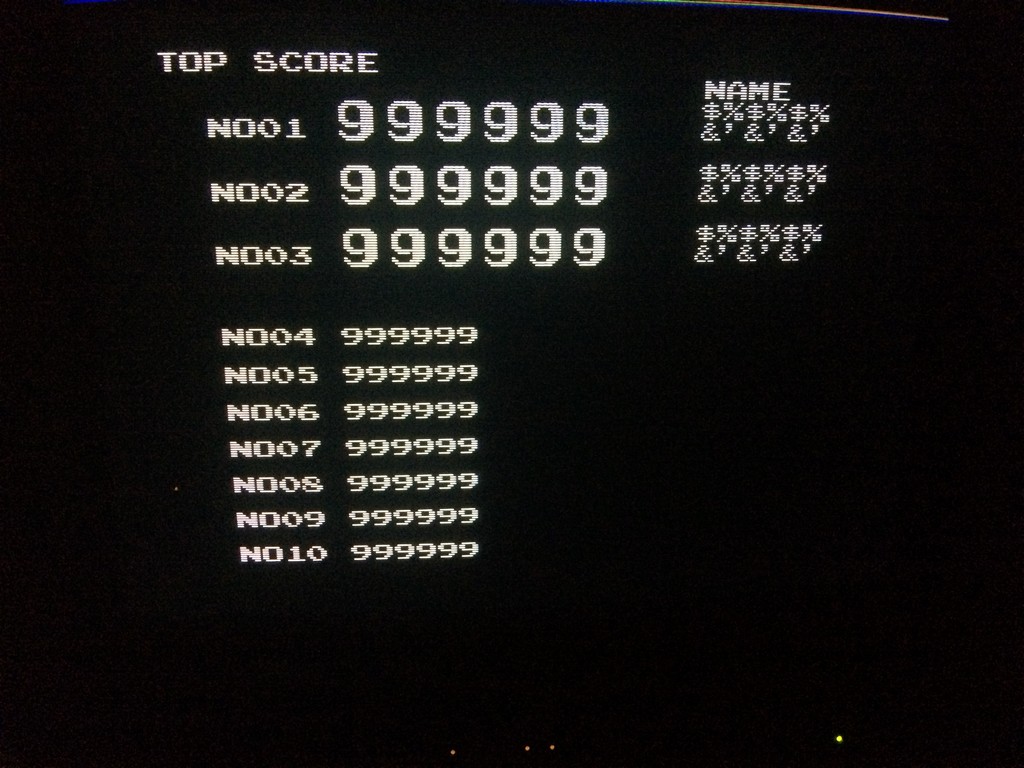
I have no TV with composite input therefore I couldn’t see both digital images and the movie of the game but the attract mode worked and I could play the game blind.

The wrong numbers were due to the missing battery.

Therefore , for the sake of completeness I put a NiMh recharcheable battery and I tested the game again.

Game didn’t boot and was stuck at the blue screen again!

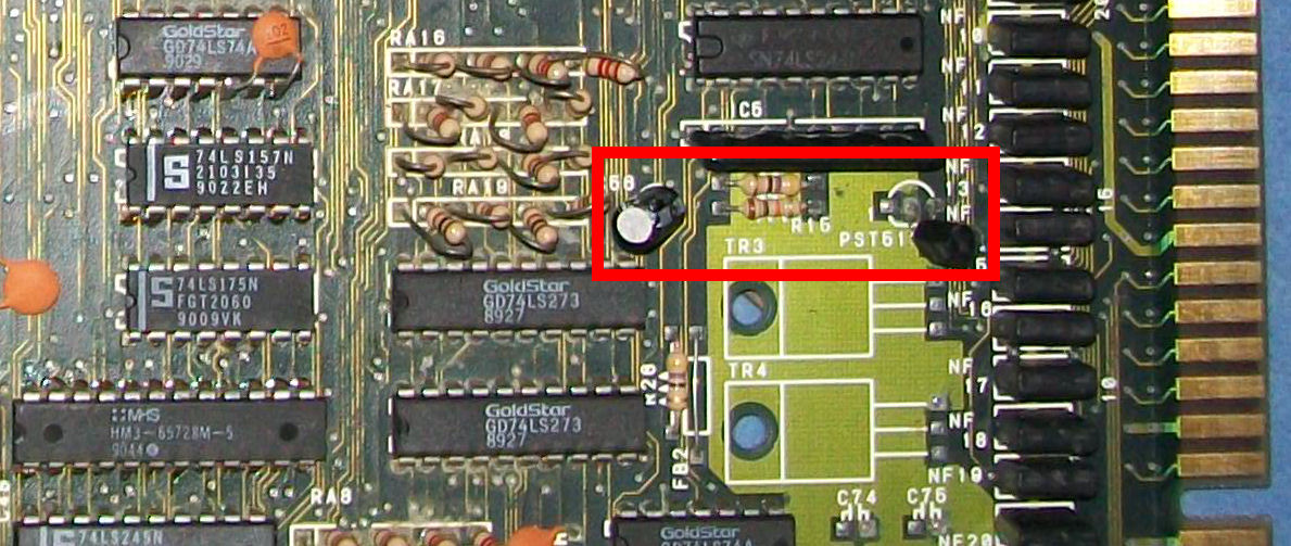
To cut  a long story short, there was a problem on the Z80 reset line.

The game randomly started but not always, and the battery made things even worse.

At the end I found out that still the same repairer changed the original RST518A, with a BC54 transistor which held the line always high

I found another replacement IC and fixed the game 100%

Sunset Riders repair log #5

 PCB Repair Logs  Comments Off on Sunset Riders repair log #5
Feb 032017
 

Found this Sunset Riders PCB in a lot bought from a former arcade operator:

The board worked fine except for the audio, sometimes wrong samples were played and often music was not present too:

The MASK ROM check reported a bad device @1D which is the one containing samples:

Obviously I removed this MASK ROM and dumped it but it turned out to be good.This device is addressed by the near ‘053260’ ASIC which processes its data as well.Tracing connections I could figured out that this custom receives serial data from the YM2151 then mixes them with PCM data and output the whole packet to the YM3012 DAC so it’s something more than a samples player, this would explain why sometimes music was missing too.Before replacing the ‘053260’ ASIC I analyzed it with a logic probe and found its pin 10 totally silent, this had to be connected to pin 16 of two 74LS245 @13F and 14F which allow 8-bit of data exchanging between the ASIC and main 68000 CPU data busses.

A simple jumper wire cured the issue.End of job.

 Posted by at 11:26 pm

Demon’s World/Horror Story repair log

 PCB Repair Logs  Comments Off on Demon’s World/Horror Story repair log
Jan 282017
 

Got this Demon’s World PCB (also known as Horror Story in Japan but game is multi-regional since it can be configured for different regions via the DIP switches) for a repair :

Board was not working, upon boot it showed the typical black/white stripes (common to all Toaplan boards) sign that main 68000 CPU has properly been initialized but then sat on a black static screen :

As said the CPU was properly running on power up but then halted before entering in game, data/address busses were both silent, usally this happens when CPU can’t find addressable devices.So I went to piggyback RAMs on board.When I did it on four 62256 @18F, 19F, 21F, 23F  :

I got this error:

I removed the four chips, most of times they resulted good when tested out-of-circuit but sometimes they randomly failed due probably weak cells.Infact when I installed new RAMs I was greeted by this screen:

Board perfectly working, no further issue found.Another repair log archived.

 Posted by at 10:09 am

Vapor Trail – Hyper Offence Formation repair log #1

 PCB Repair Logs  Comments Off on Vapor Trail – Hyper Offence Formation repair log #1
Jan 192017
 

Sometimes it’s just matter of capacitors…We could call this repair log in this way, let’s read why.

I bought this not working  Vapor Trail – Hyper Offence Formation PCB on Ebay:

The board gave a static blank screen on power up:

Like other Data East games, hardware uses as main CPU a custom 68000 marked ’59’ :

Here you can see its pinout figured out by Porchy some time ago:

Data East ’59’ 68000 CPU Info

Probing it revealed static address/data bus, clock was present instead.Since it was not included in the above pinout I spent some time to figure out that pin 59 was the /RESET one.Probing it I found that on power up there was no transition from LOW to HIGH but pin went directly to HIGH state hence CPU didn’t get initialized.RESET circuit is a typical one made of the PST518 voltage monitor IC, a 47uF 50V electrolytic capacitor and a couple of resistors :

Checking in-circuit the ESR of this 47uF 50V capacitor @IC56 gave no reading, value was out of the 100Ohm range of my meter:

I removed it and out-of-circuit testing confirmed this capacitor was bad:

Replacing it restored a proper RESET signal so board successfully booted:

But sound was quiet despite adjusting the potentiometer and some interferences were present on screen too:

I went to measure the impedance of the electrolytic capacitors in analog sound circuit and I found many of them with out-of-specs value:

I replaced them all :

This restored a loud and a clear sound.As said in the beginning, it was only matter of capacitors!

 Posted by at 7:06 pm
Jan 092017
 

Received this Wild West C.O.W. Boys of Moo Mesa PCB for repair:

PCB was very dirty with flux residual and rust so I first washed it.After dried I powered it up and was greeted by this screen:

The initial self-test reported a bad ROM @T5 and a bad RAM @J4, obviously the board didn’t boot up but kept resetting.Usually Konami testing routines are very reliable so I went to dump the four program ROMs and actually the one @T5 showed at offset 0x3FFB4 a difference  of only one byte (well, one nibble..) compared to the MAME dump:

I reprogrammed the EPROM (a 27C020) and error was cleared but obviously the one regarding the RAM @J4 was still present:

RAM @J4 was one of the three RGB 2K x 8-bit palette RAMs :

Piggybacking it had not effect so, before removing the chip in order to test it out-of-circuit, I checked its connections with a multimeter.All was fine until  I could measure a short between pin 21 (/WE) of the RAM and VCC :

This explained why the RAM was reported as bad as it was never be written (write enable signal is active low).The /WE signals of the other two RAMs are generated by the near ‘054338’ custom :

so I went to inspect it with a digital microscope and found two bridged pins:

I removed the bridge and board successfully booted but sound was totally missing:

This is a common issue on these Konami board that use the ‘infamous’ hybrid audio module.This board has the ‘054986A’ one :

Usually you can fix this issue by replacing the capacitors but I opted for a drastic solution removing the module and installing two rounded machine-tooled strips with 1.778mm of pitch:

Lastly I used one of my ready module:

Job done.

 Posted by at 10:27 pm