Jul 092017
 

In this log I fix the sprite’s incorrect colors as discovered in part 1. To review the problem see the image below. Note that the colors for the weightlifter are incorrect, the runner also has red shadow instead of black and the colors for the area in between the flags on the right are also incorrect.


Initially, I thought the area between the flags were actually made up of background tiles. These are actually sprite objects used as background graphics. I used my test rom to confirm this.


The bipolar proms I ordered finally came but were all faulty! So that was a complete waste of time and money. The good news is after checking the palette prom [ several times over ] it appears to be good and I must have been reading it incorrectly with my TopMax in part 1 of the repair log.

I thought about this for awhile and had an idea that would help me troubleshoot. Firstly, I looked at the color palette for Hypersports in MAME and took down some notes.


After comparing the colors of the sprites from images online [ google images was a good starting point ] with colors from the table above, my suspicions were that there was a stuck bit somewhere. Black [ color 0 ] is being displayed instead white [ color 1 ].

For black [ color 0 ] to be displayed instead of white, bit 0 would have to be stuck low. Color 2 is also being shown instead of color 3 and the only way this could happen is if bit 0 was stuck low. The athlete’s shadow is also being shown as red instead of black for the same reason which results in color 8 being shown instead of color 9.


The backgrounds and sprite data appear to be combined at the LS157 at A4 which then form the signals OUT0-OUT4 at the LS174 A2. These 5 signals represent the color of a single pixel on the screen [ 32 possible colours ]. But I’m more interested in the signals OCOL0-OCOL3 [ object/sprite colors ] so I begin poking around at the inputs and outputs of the LS157 at C17 first. I generally choose the multiplexers to troubleshoot first whenever it’s relevant because these seem to get worked fairly hard [ especially in the video circuit ] and exhibit higher failure rates in these areas.


Pin 4 [ 1Y ] output of C17 appears to be stuck low, exactly what I was looking for. This was later confirmed after testing the chip out of circuit.


The Fujitsu in C17 is a temporary measure, I promise. It’s a working pull from my Gyruss and I didn’t have any other spares on hand.


The colors seem right although I seem to be missing overall color from the CRT.


Changing it over to my LCD just to confirm that my 1084 probably needs an adjustment of some sort.


Jul 012017
 

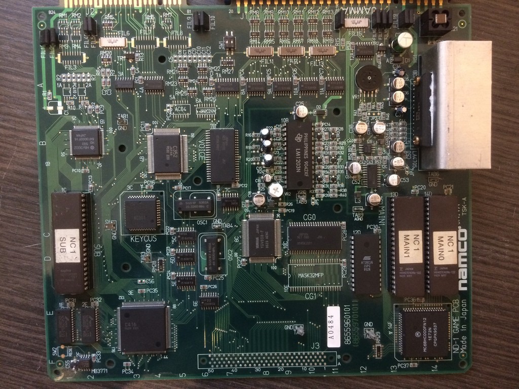
These system boards from Namco has a common problem: SMD capacitors

These caps expecially the ones produced in the 90s are very unreliable and sooner or later will start to leak

On my boards there isn’t one that has the ESR in a good range.

On Namco system NA ( Emeraldia, Tinkle Pit, Super World Court) or NB ( Point Blank, Nebulas Ray), the problems you will face are sound related ( low sound or scratchy ), on ND system ( Namco Classic Collections), the SMD caps are used also for the RGB amplifier and in addition you will get colour problems.

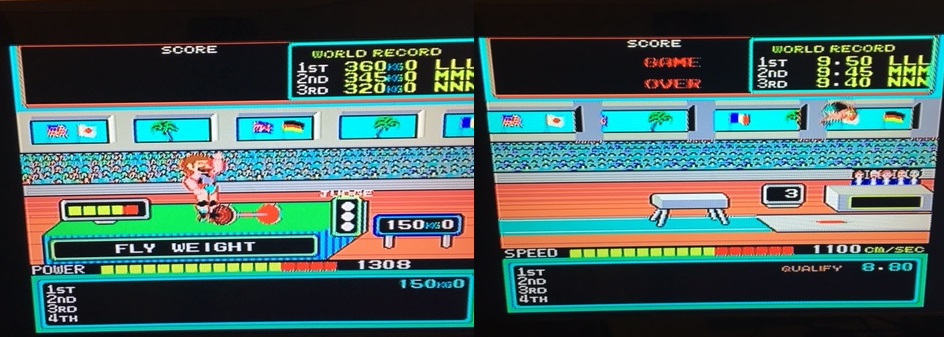
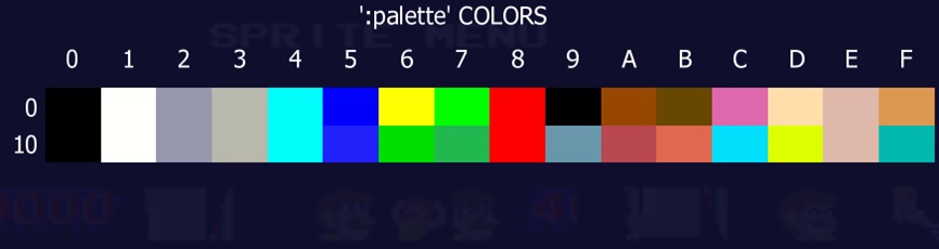
I will take as an example a Namco Classic Collection I just finished to repair and which had all the problems coming in about one week of intensive use after a while in storage.


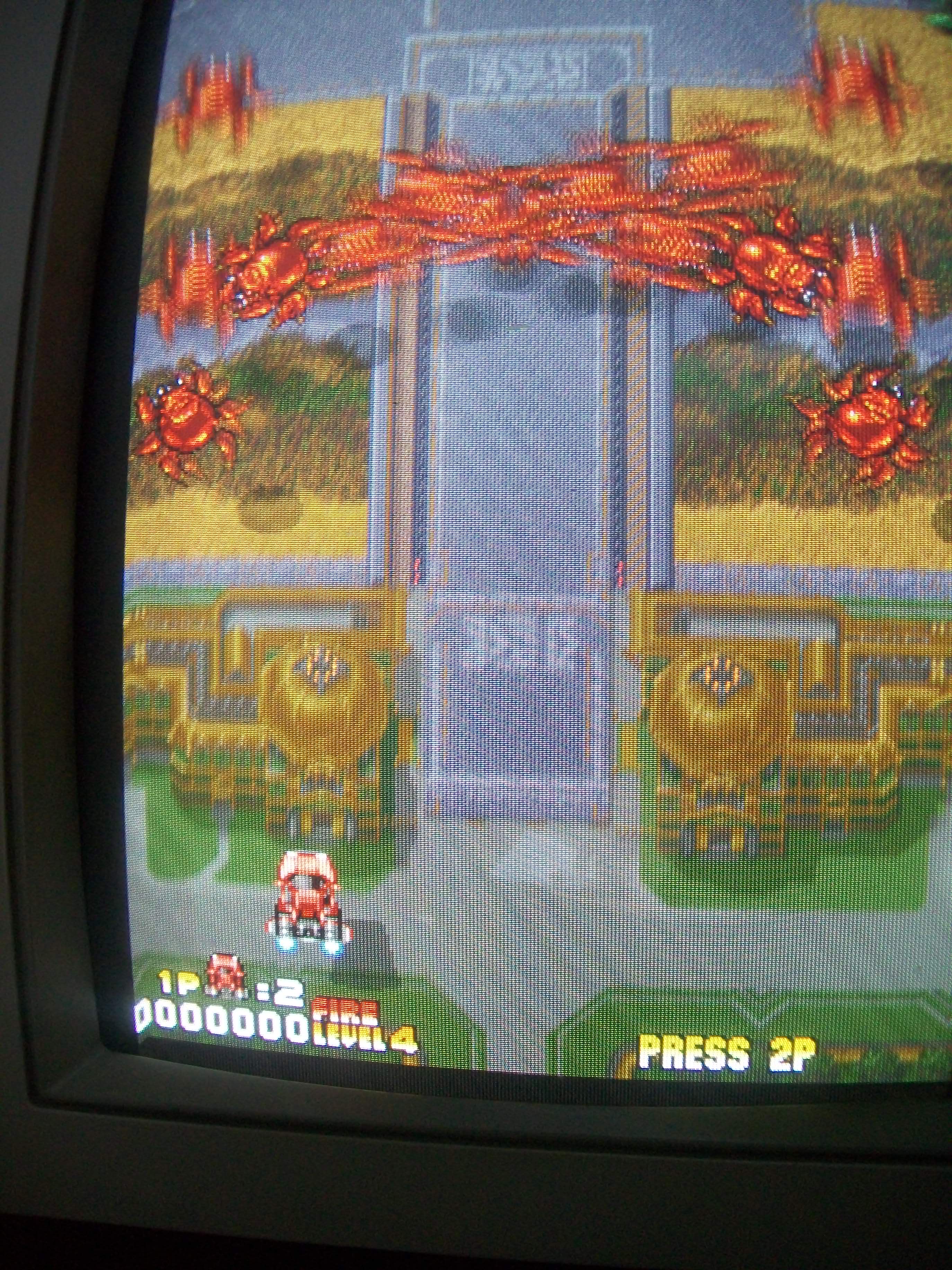
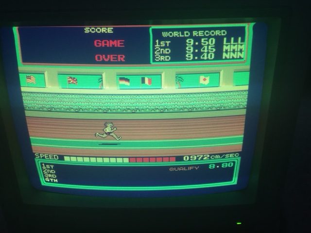
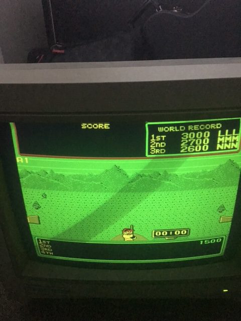
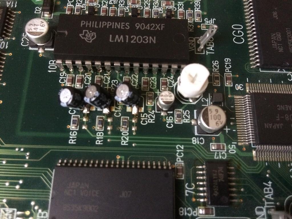
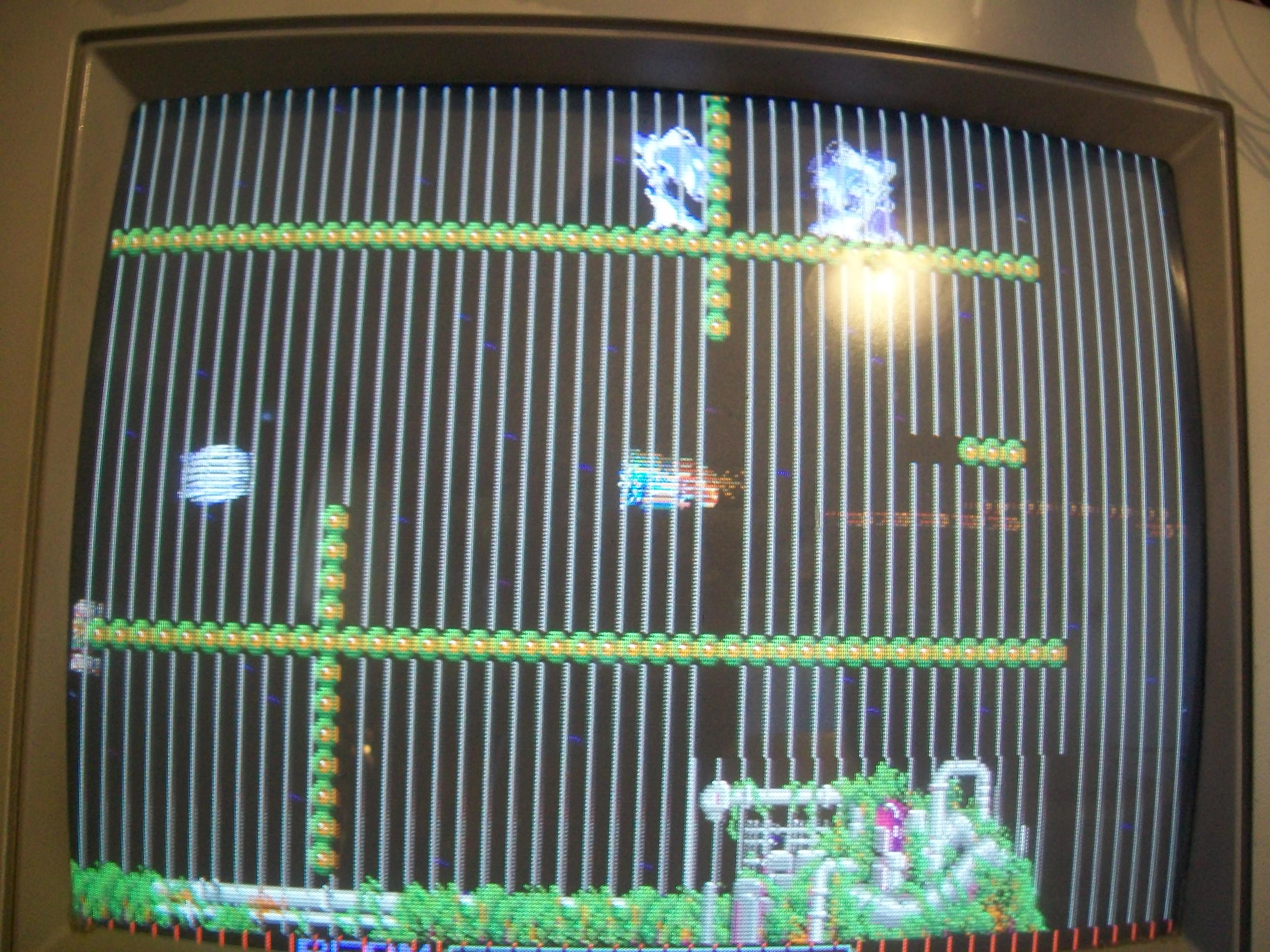
First of all it started to have trails on the RED component of the image.

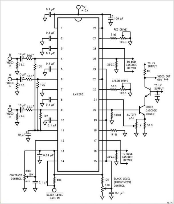
The system uses a common RGB amplier LM1203 which for example is used on the majority monitors neckboards

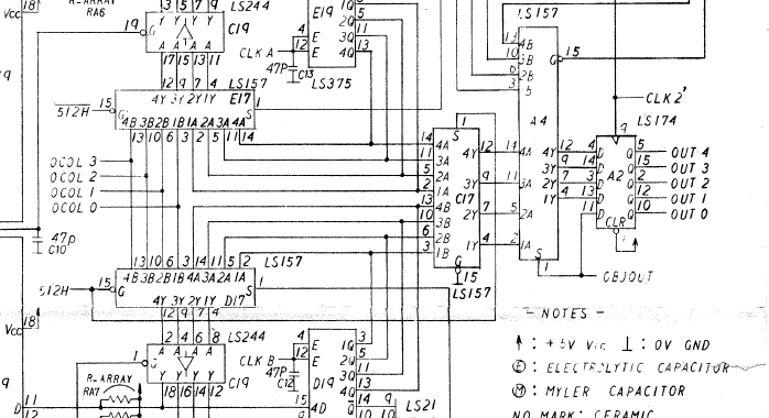
Here are the usual circuit taken from the schematics of the LM1203:

As you can see , on the inputs of each colour component you have to place a 10uF cap.

Namco engineers decided to use a 4,7uF but I tested and there are no differences between the two values.

So, if you have colour quality problems on your Namco Classics Collection pcbs, first thing is to recap the RGB input section using commercial

electrolitic caps.


I am not a fan of brute force recap, so with my ESR meter I usually check all the caps and change only the ones that have a very out of range value.

As said before, after few days I get no sound for a while and after about 5 minutes, you could hear it coming up but very scratchy.

The amplifier got also really hot after a short time.

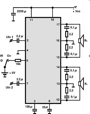
The system uses a LA4705 sound amplifier


I probed with the ESR meter all the caps and found out the both the small ones 2,2uF placed on  IN1 and IN2 had a value of more than 99 ohms.

The other ones also were really not in the specification range but to get sound back it was enough to change the small ones.


As said the sound section of Namco system NA and NB is the same more or less, therefore if you start to have low sound and you don’t have an ESR meter,

change the 2,2uF, 47uF (33uF on the amp schematics) and 100uF one.

Jun 282017
 

Got some months ago in a trade this pretty mint original R-Type board:

Board was faulty, it was stuck on this static screen:

System is made of three boards:

  • ROM board

  • CPU board

  • Video Board:

Swapping all the boards with a good set I could figure out that none of mine was properly working.So I started to troubleshoot the ROM board since it’s the most simple.The program ROMs were dumped as good but I found a bad 74LS245 @1A:

This gave me a working ROM board and a good starting point so I moved on to troubleshoot the CPU board.Analyzing the NEC V30 (uPD70116) main CPU revealed the interrupt line was asserted (active high on this CPU), here’s a screenshot from my scope triggered with RESET signal

The interrupt is generated by the uPD71059C  Interrupt Control Unit , probing it revealed that input pin 3 (READ STROBE) was stuck low :

This comes from output pin 12 of a 74LS244 @IC72 :

I pulled it :

It failed the out-of-circuit testing:

Finally the board booted but with multiple issues.First noticeable one was a totally missing sound but this was because the analog audio section was modified (by factory) to work in Nintendo cabinets.I simply reverted the mod by installing the missing capacitors @C101, C102 an C108 and removed the jumper wire:

All the other issues concerned the graphics.Some examples:

Honestly it would take too long to explain in details what I did (and maybe I even lost track of it…) before the board worked fine again :

All I can say is that I had to replace  in total 15 TTLs (all from Texas Instruments, are we facing another Fujitsu perhaps?)

But I claimed victory too soon , the board went bad again showing jailbars all over the screen:

I quickly pinpointed this further failure in one of the two ‘KNA6034201’ custom tiles generator on video board:

Testing it on a Kung-Fu Master PCB  (where it’s used for sprites too) gave me confirm it was really bad :

Looking at this PCB I noticed that the other custom ‘KNA6034201’ was replaced by a little sub-board:

Technically speaking the custom acts like a big shift register, it can take up to 24 bit of data from tiles or sprites ROM.As you can see in the sub-board picture above the custom functions have been reproduced using six 74LS166.So I wondered myself : why not reproduce it in a more modern way?I fired up my CAD and drawn schematics and touted them to a PCB layout.I sent files to manufacturer and after some time I got the bare PCBs:

Here is the final result compared to orginal custom:

Luckily I made no design mistake and testing was 100% successful.Another board repaired and another custom IC delivered to eternity!

 Posted by at 7:36 pm

Nintendo VS System repair log #2

 PCB Repair Logs  Comments Off on Nintendo VS System repair log #2
Jun 282017
 

I bought this system in a lot of faulty pcbs.

Game was booting but it had no sync and the graphic was all corrupted.

The OSC 21.477mhz was giving out around 12mhz


After changing it, the game was back to life but it was missing the blue component

Looking at the schematics , I could confirm that the RP004 video chip was giving good signal on the BLUE signal pin, therefore I started

to check the LM324 OP AMPS involved in the DAC circuit.

The output of the LM324 for the BLUE component was dead therefore I proceeded to change it but the game was not fixed yet despite now having a good signal


By turning the blue pot I could see briefly some “sparks” of blue ,therefore confirming that the blue component

was working again.

In the end it turned out that the blue pot had some cold joints on the ceramic base.

I reflowed the solder and the game was 100% fixed

Satan Of Saturn repair log

 PCB Repair Logs  Comments Off on Satan Of Saturn repair log
Jun 282017
 

Got this game cheap for my collection because the seller stated that it has very noisy sound

When powered, the game had a constant white noise while music and the other sound effects were working correctly.

The sound problem was not due to the amplifier or bad caps but it was produced by the logic of the game.

To make a long story short, this game has a similar circuit to what Space Invaders use to produce analog sounds.

It uses a SN76477, which is a programmable sound chip which has a white noise function.

On Space Invaders and in this game, the chip continuosly output the white noise which is switched OFF and ON using operational amplifiers and it is modulated with capacitors and resistors to produce different sounds.

I downloaded the schematics from the US version ( called Zarzon ) where it is shown how the chip is connected to the LM3900 OP AMPS


Instead of trying to understand which of the two chips are broken, I piggybacked a good one on both chips until

the white noise disappeared.

Problem was fixed by changing the LM3900 Nr.47 on the schematics