Robocop repair log #3

 PCB Repair Logs  Comments Off on Robocop repair log #3
May 162018
 

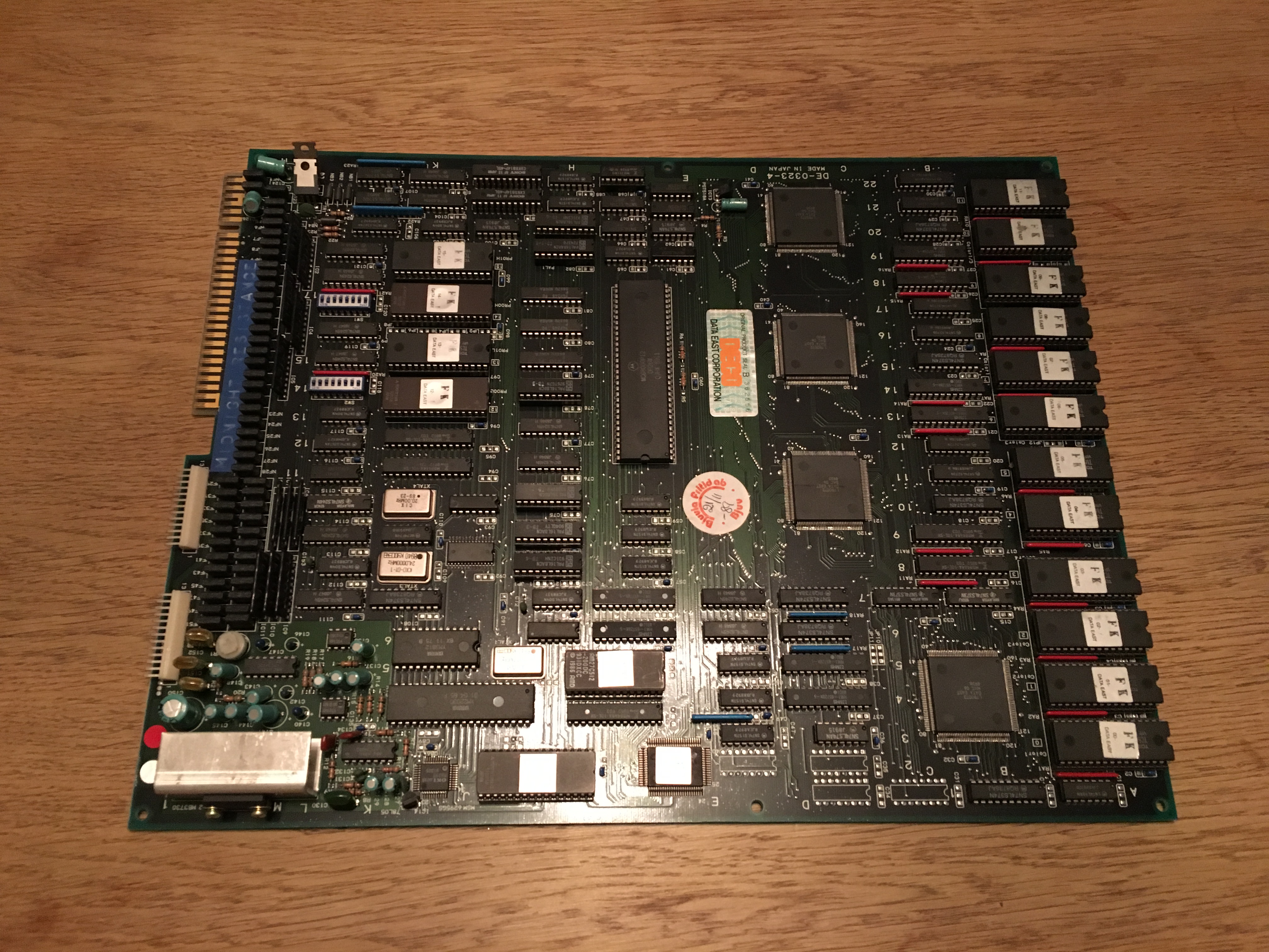
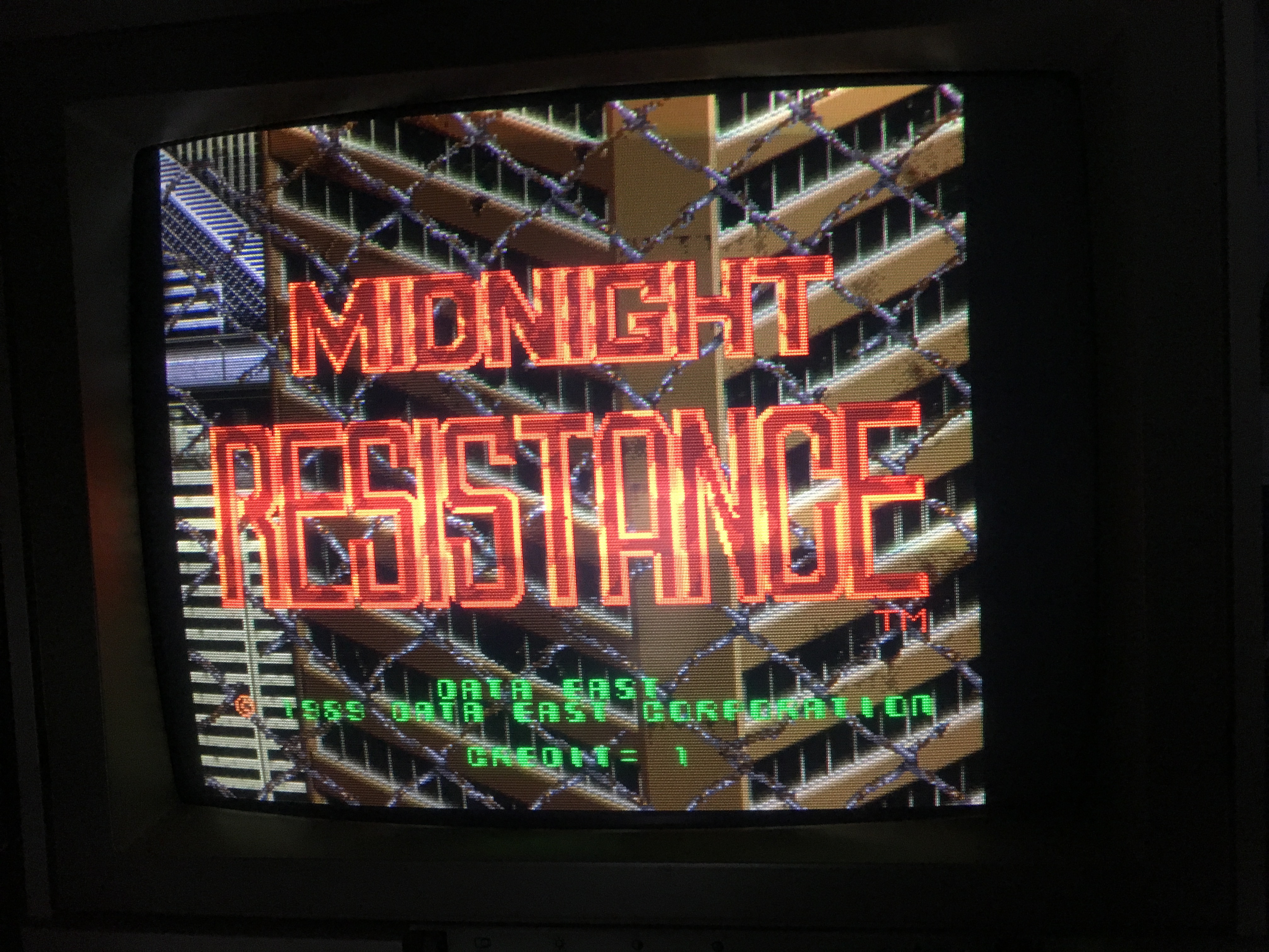
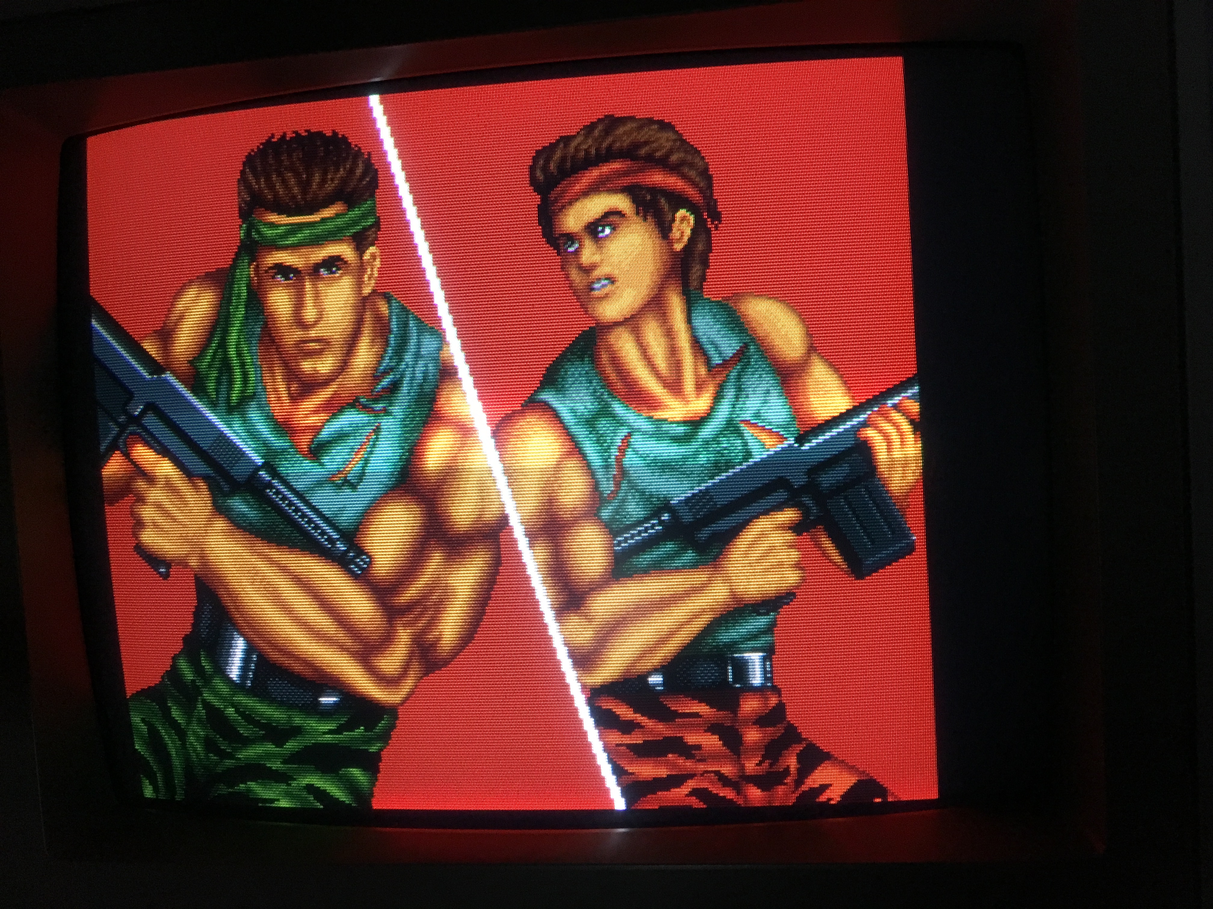
I got this Data East Robocop pcb from a friend that was totally dead.
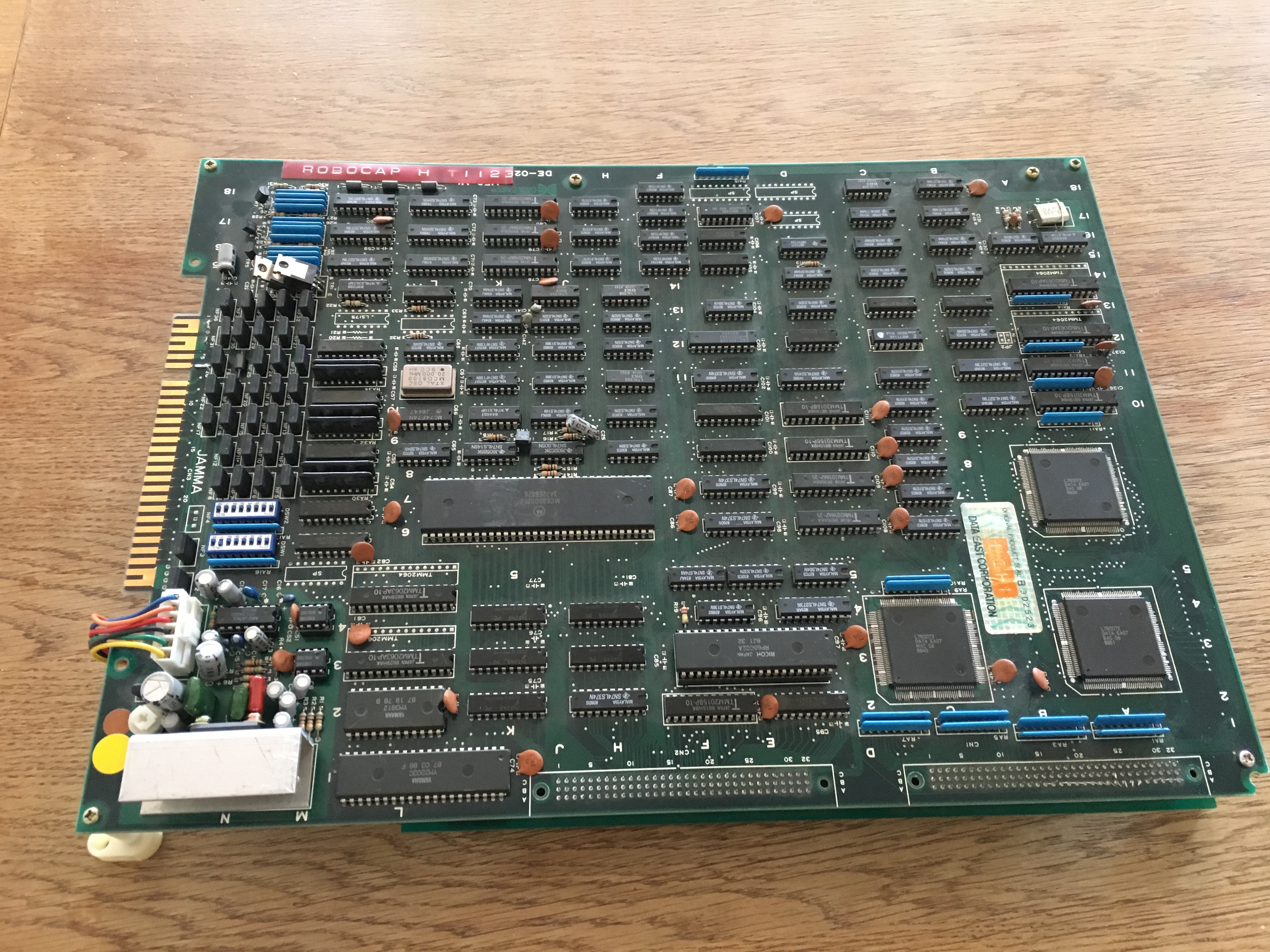
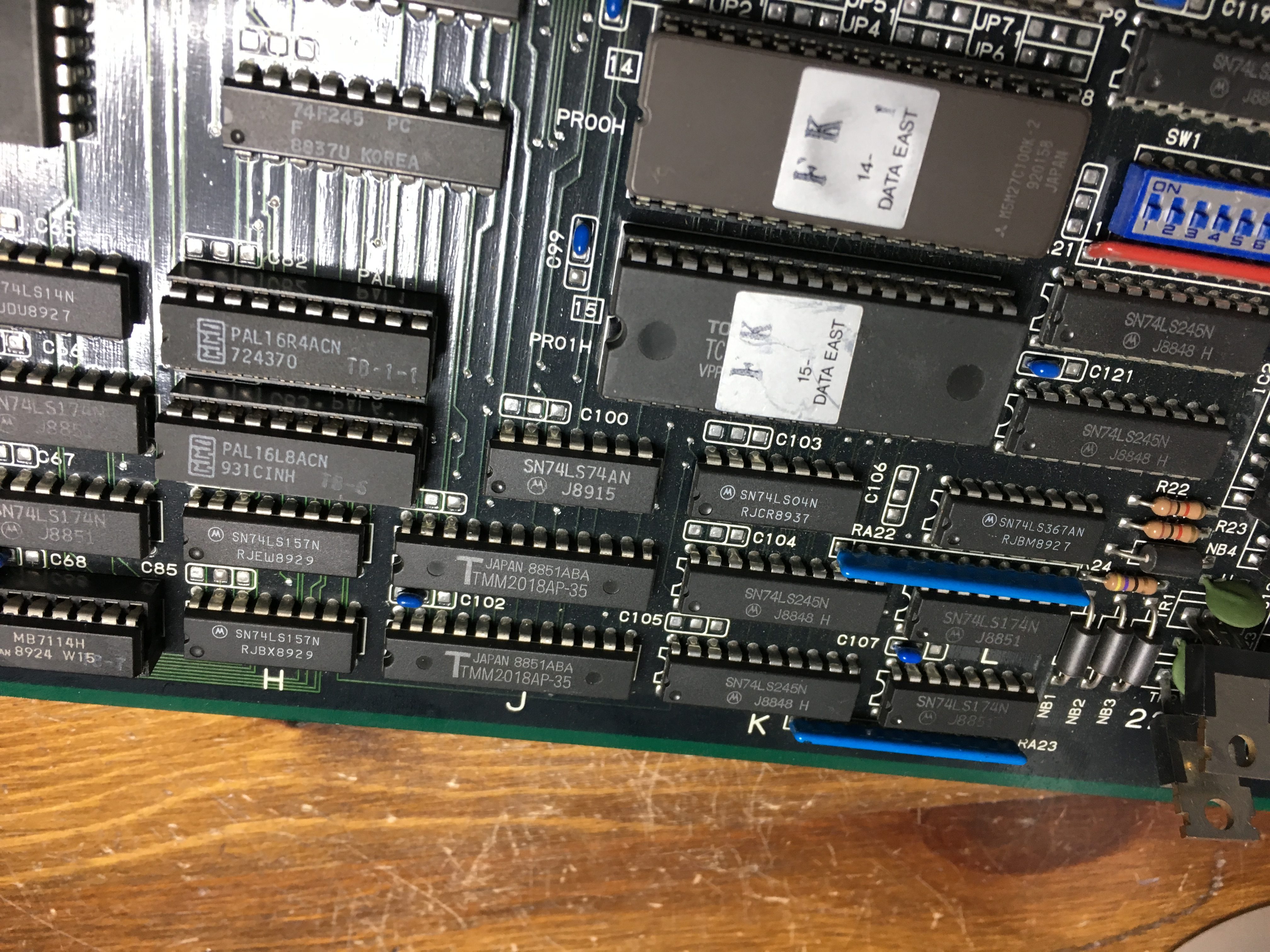
I had more Data East pcb’s around so I could test the bottom ROM board with one of those CPU boards and it was also not working. So I started pushing the EPROMs in their sockets and after that the game booted up.

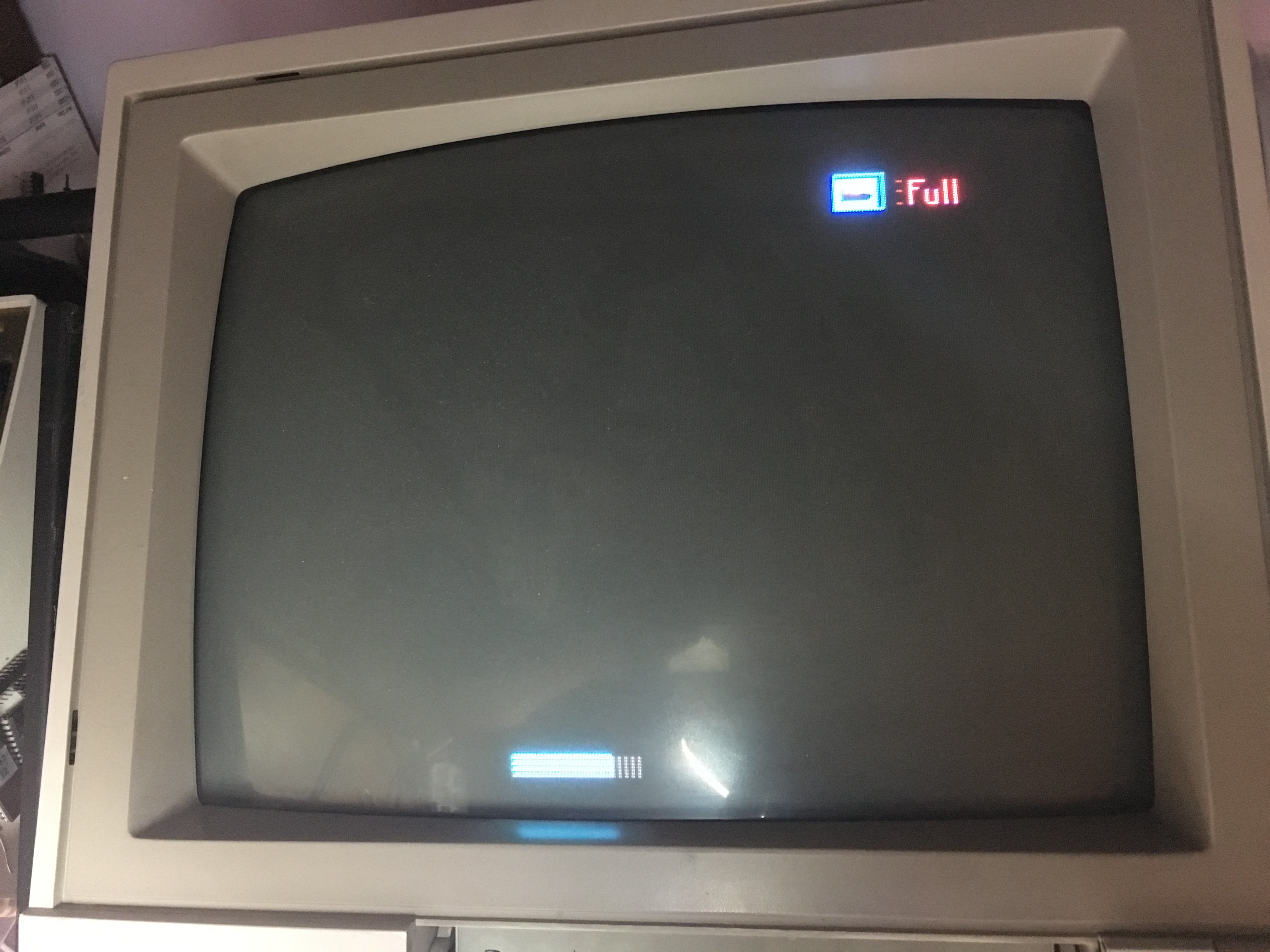
So now I tested the ROM board with it’s original CPU board and game booted but the screen was almost completely black apart from some graphical elements like the energy bar.
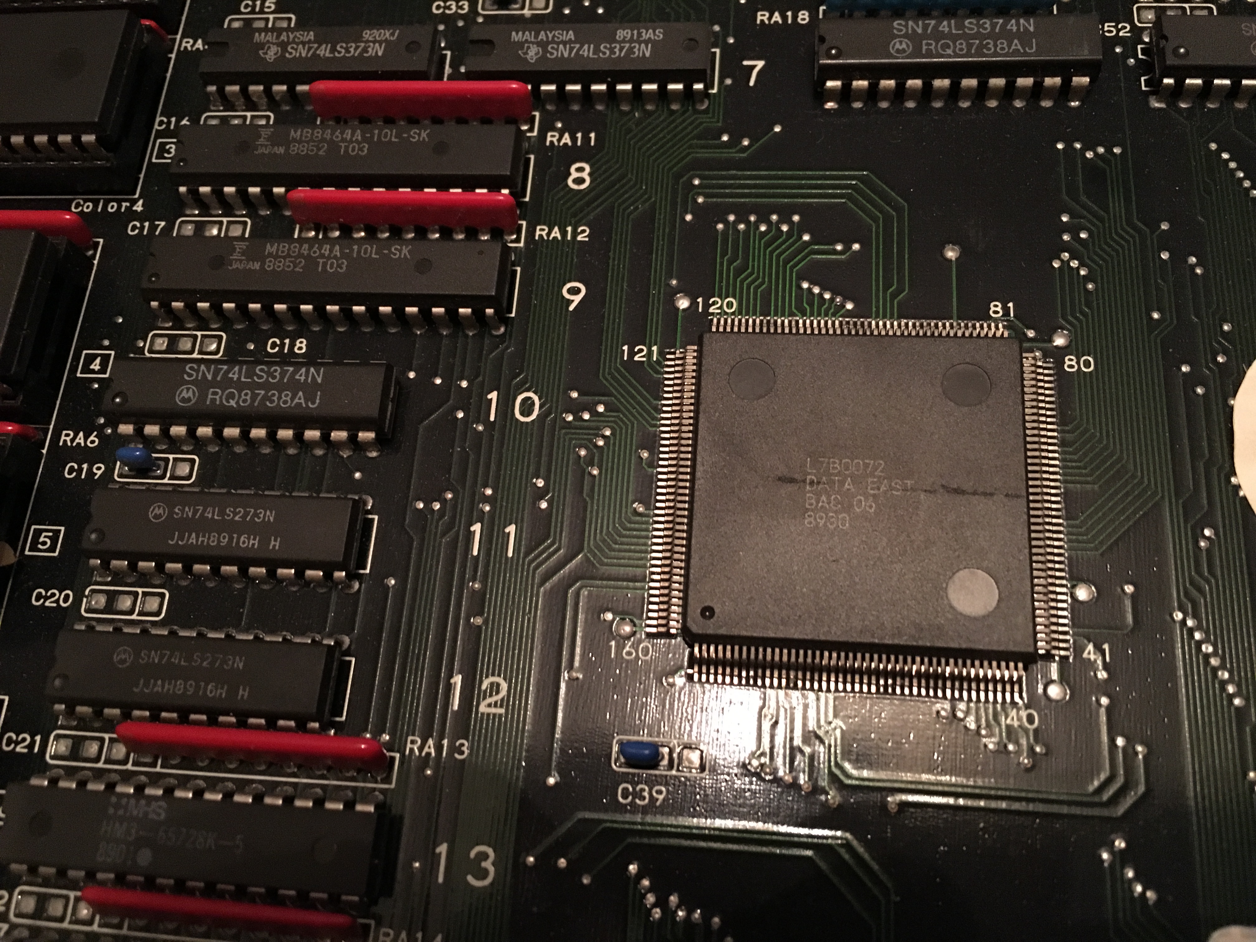
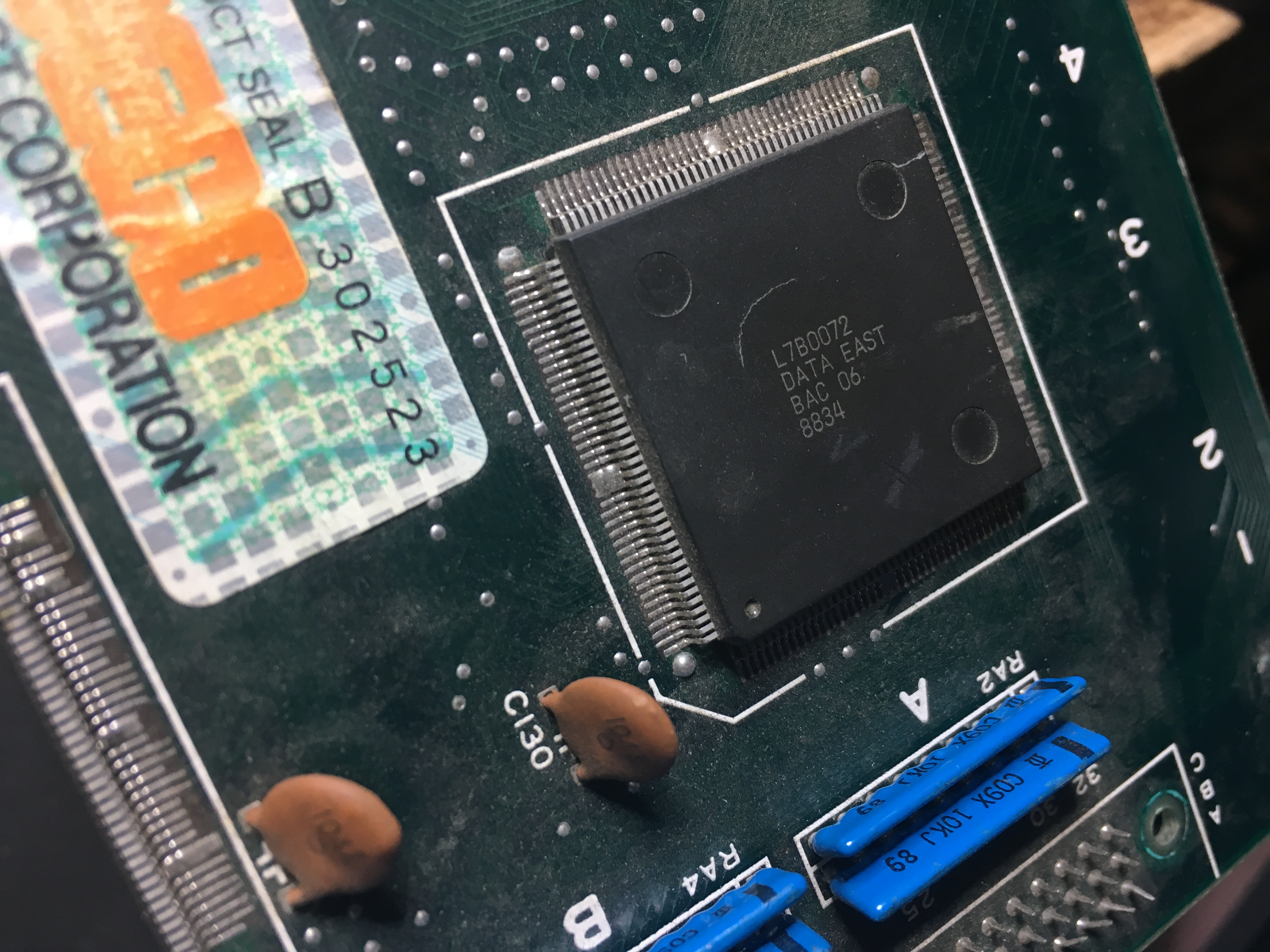
After visually going over the CPU board I found that one of the custom ASIC L7B0072 had a crack in the center of it.
I had a broken Midnight Resistance board (not the previous repair) that had this ASIC, so I opted to transplant it over to the Robocop board.

I noticed that the top of the ASIC had a brownish discoloration, but I didn’t know if it was toast or not, so I desoldered it with my hot air station and soldered it onto the Robocop board.
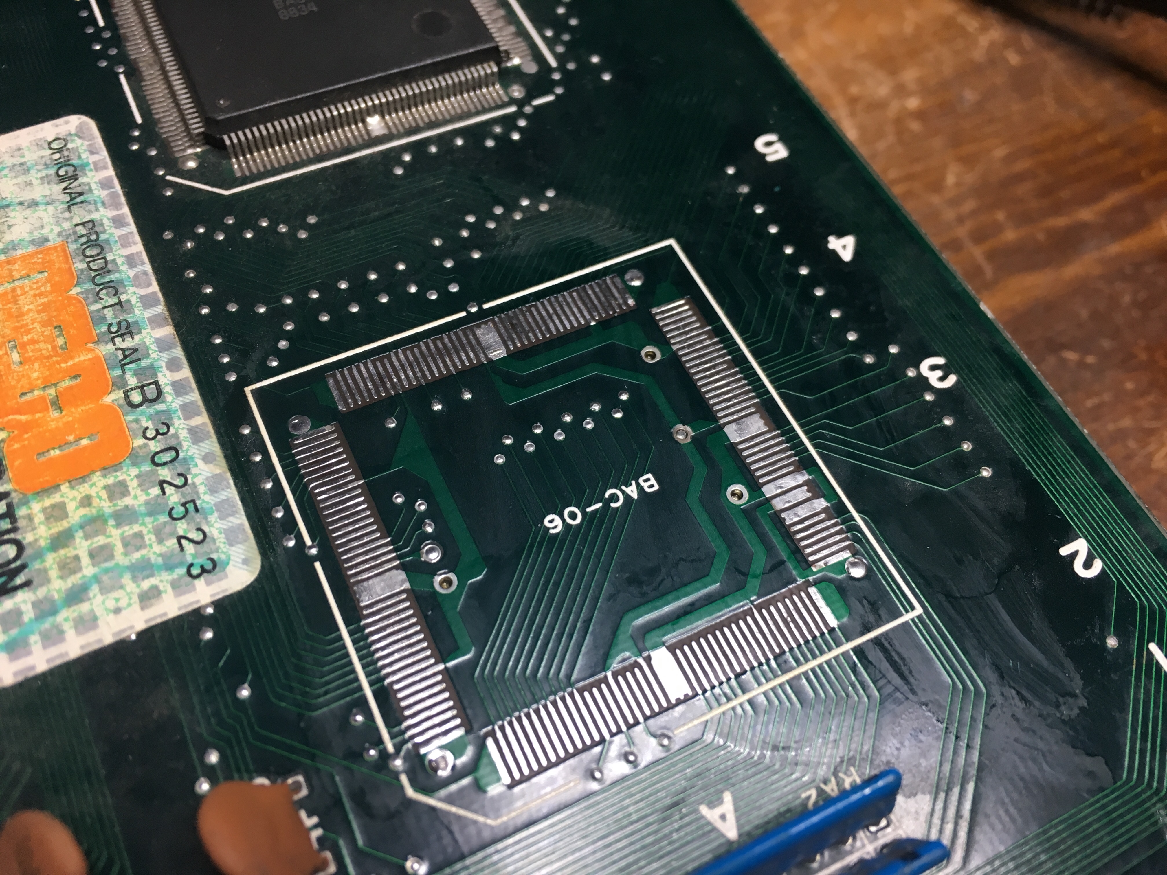
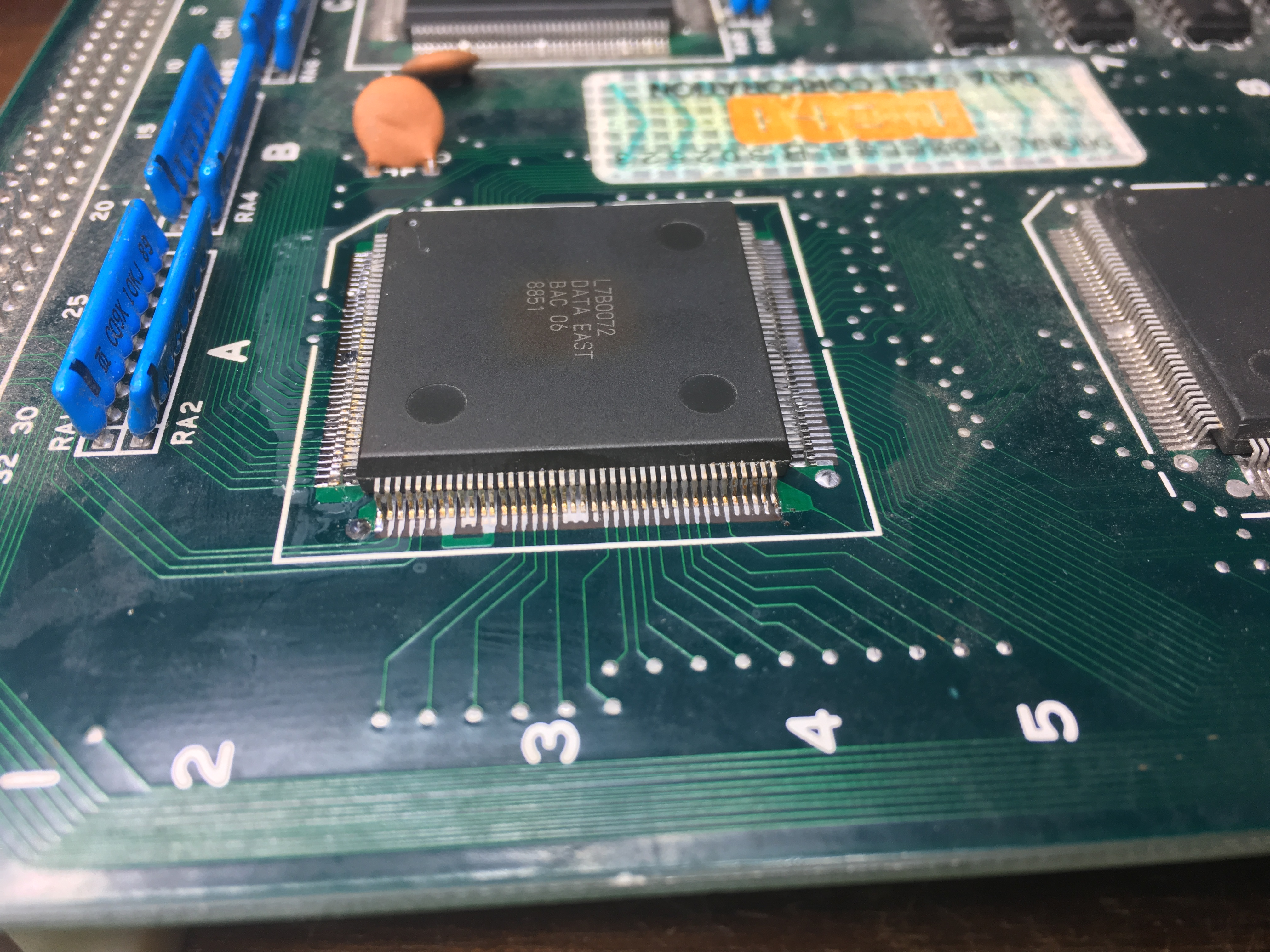
Confirmed that there were no shorted pins on the ASIC and booted the game, but unfortunately the transplant did not help. Some graphics appeared, but mostly scrambled characters and when coining up and pushing start, the game reset. (forgot to take a picture)

After having a conversation with caius (thanks again for all your advice) we opted to do another transplant but with a better looking ASIC.

Redid the procedure, hot air station to remove the ASICs and then soldering again and lo and behold, the game has good looking graphics once again 🙂
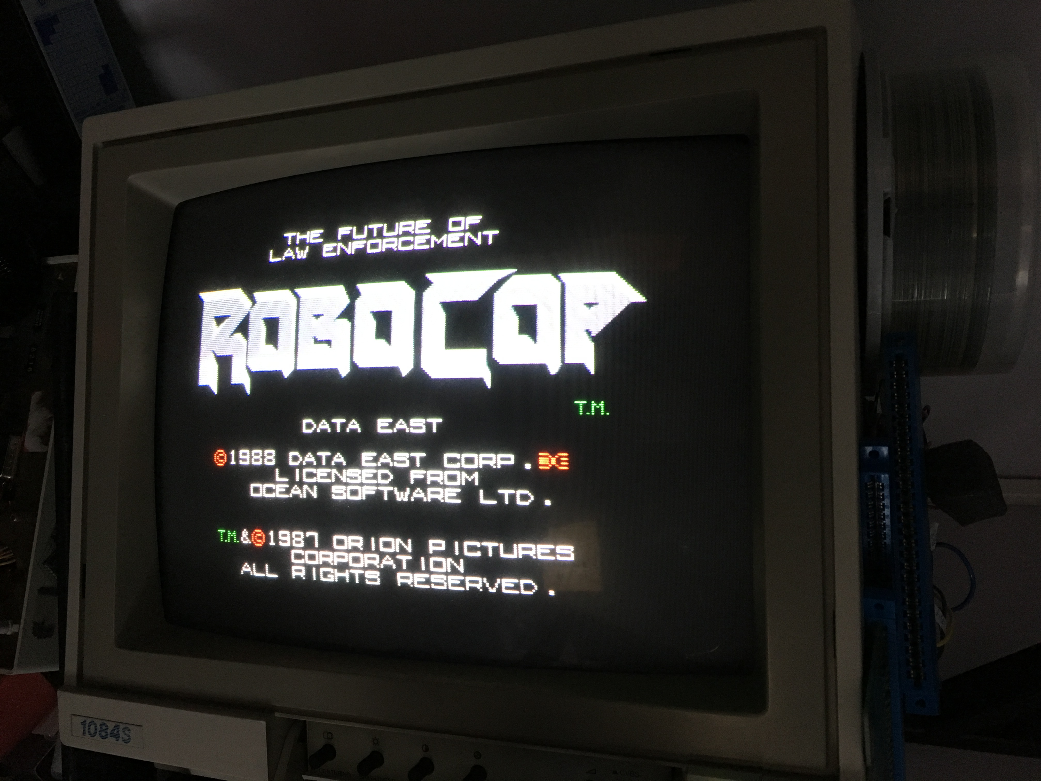
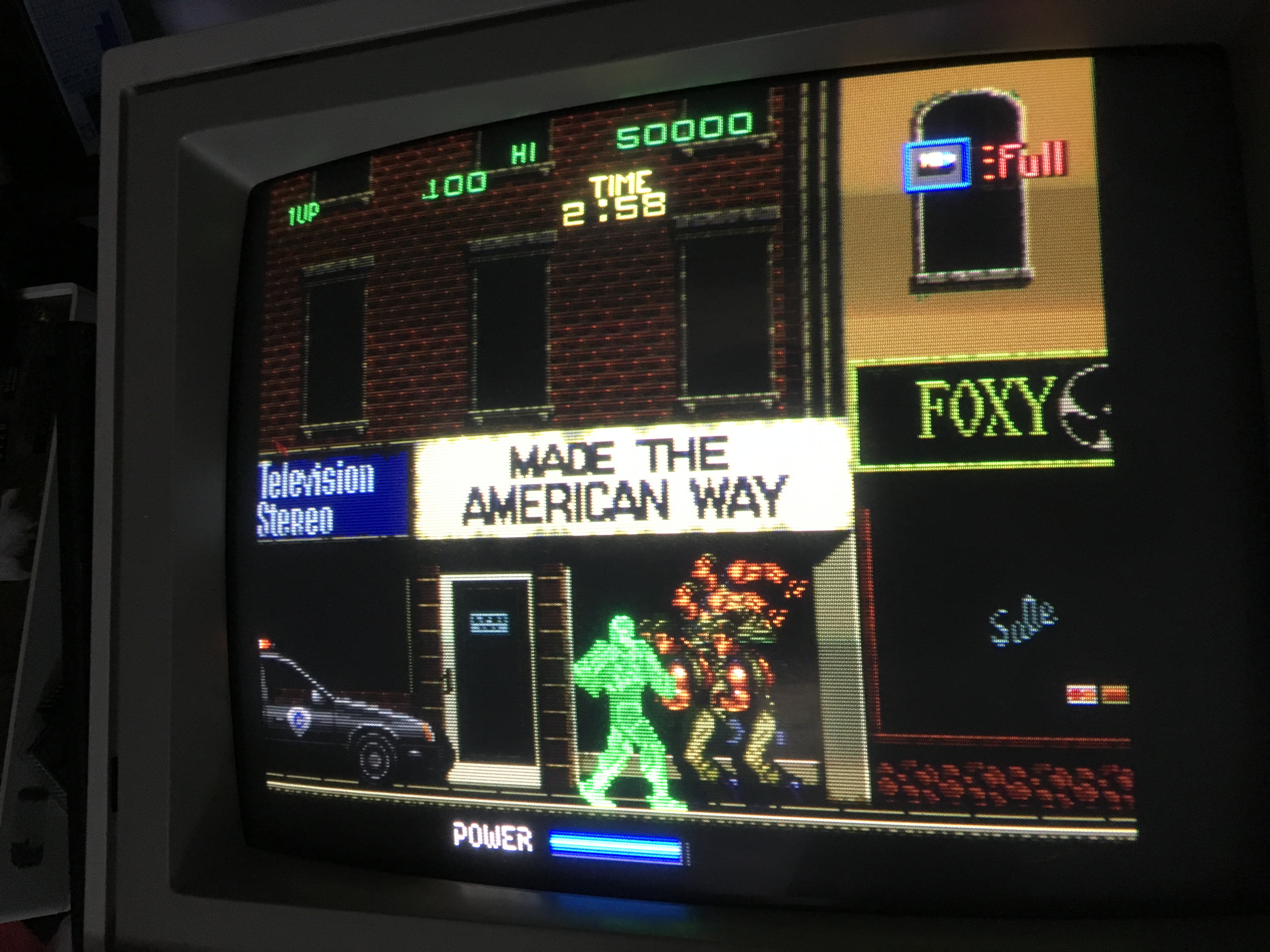
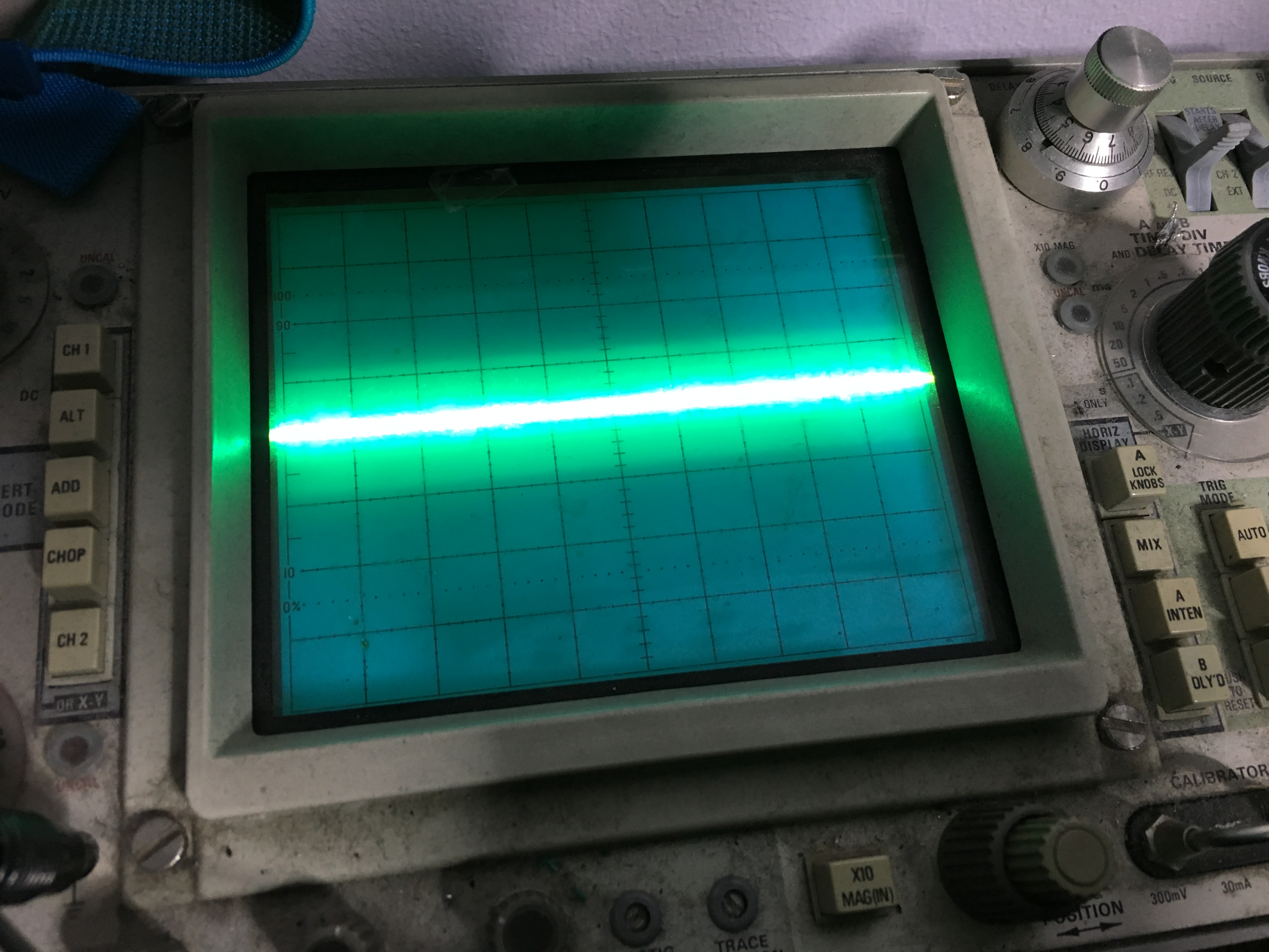
But I quickly noticed that there were no audio at all. Using my audioprobe I found that there were music been generated by the YM3014 at 4M and FX from the YM3014 at 3M and then going to the OP-AMP 3403 at 4N
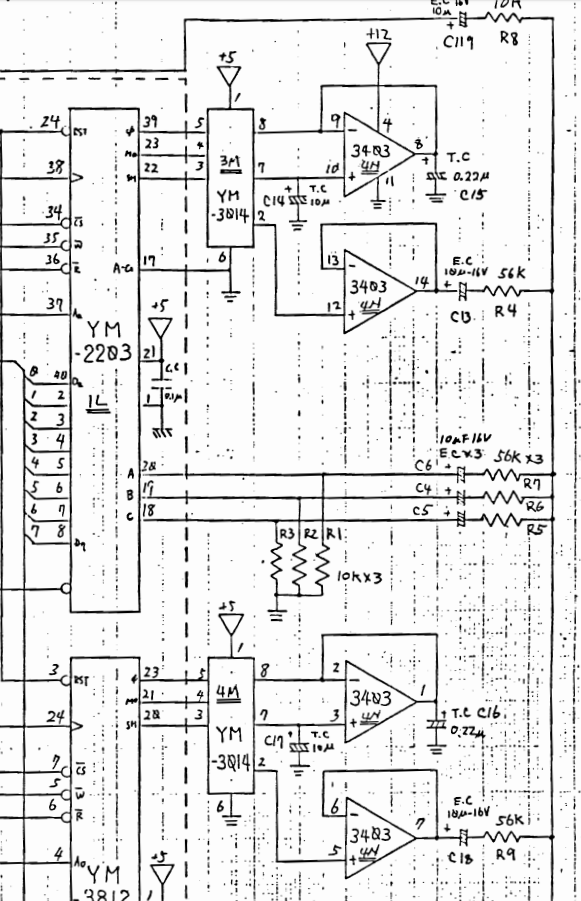
Nothing came out of the 3403, so I eventually found that there were no +12V input on pin 4 of the 3403. Checked the JAMMA edge and found a broken track. I guess that the operator had some form of voltage measuring device and somehow broke the track at some point. I soldered a little metal wire to bridge the gap and booted the game again.
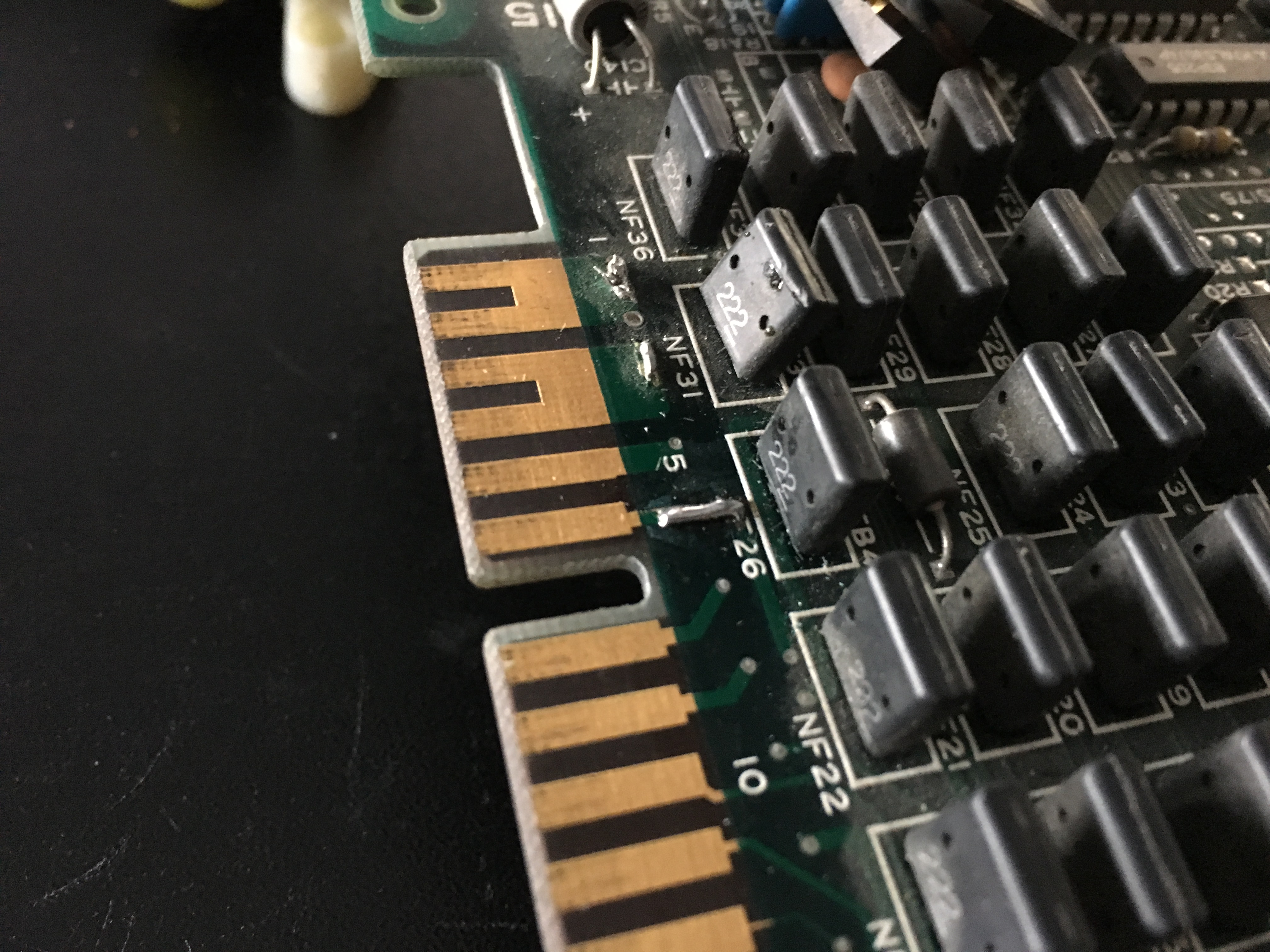
Now audio could be heard for a short second and then silence again.

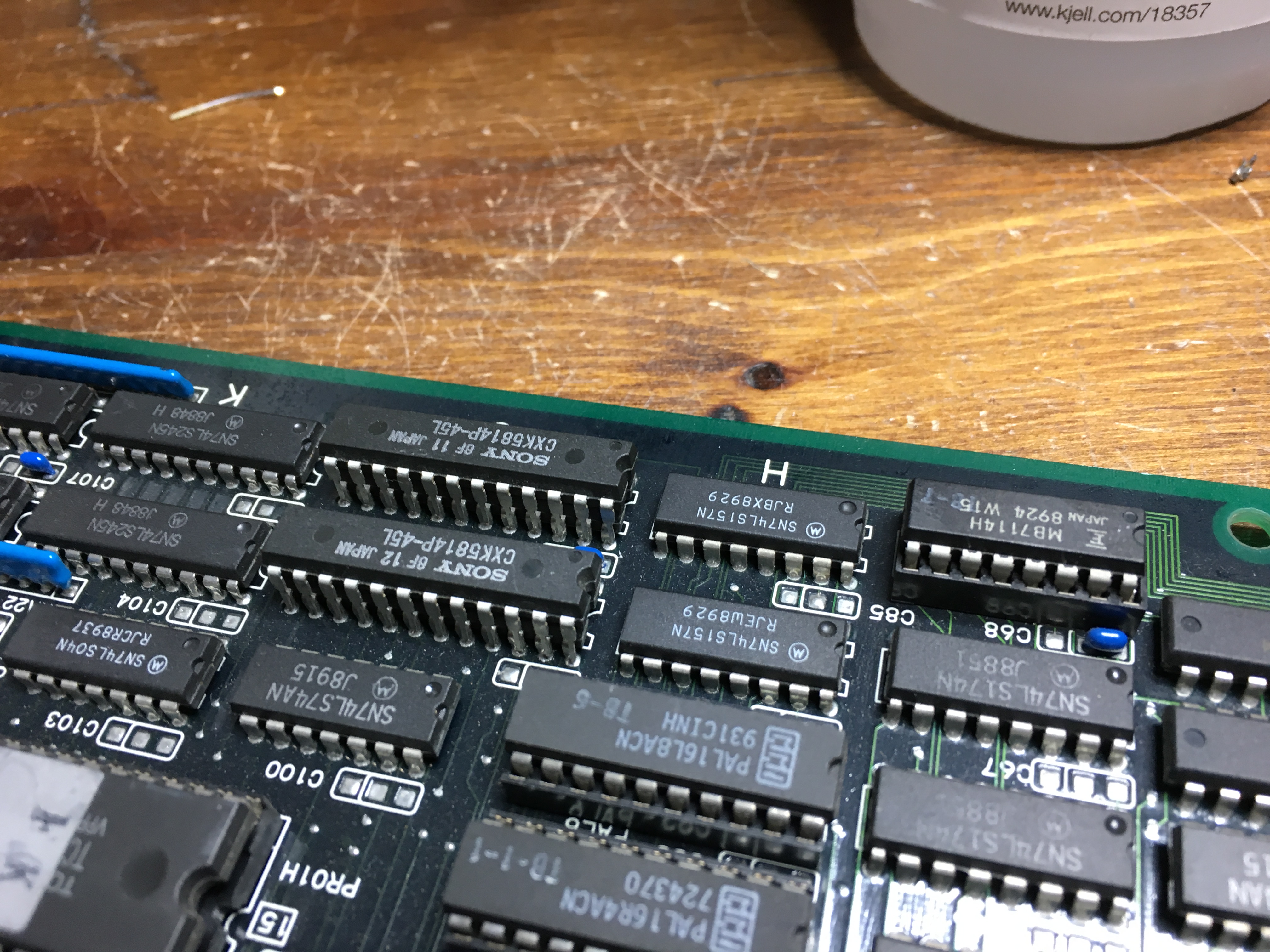
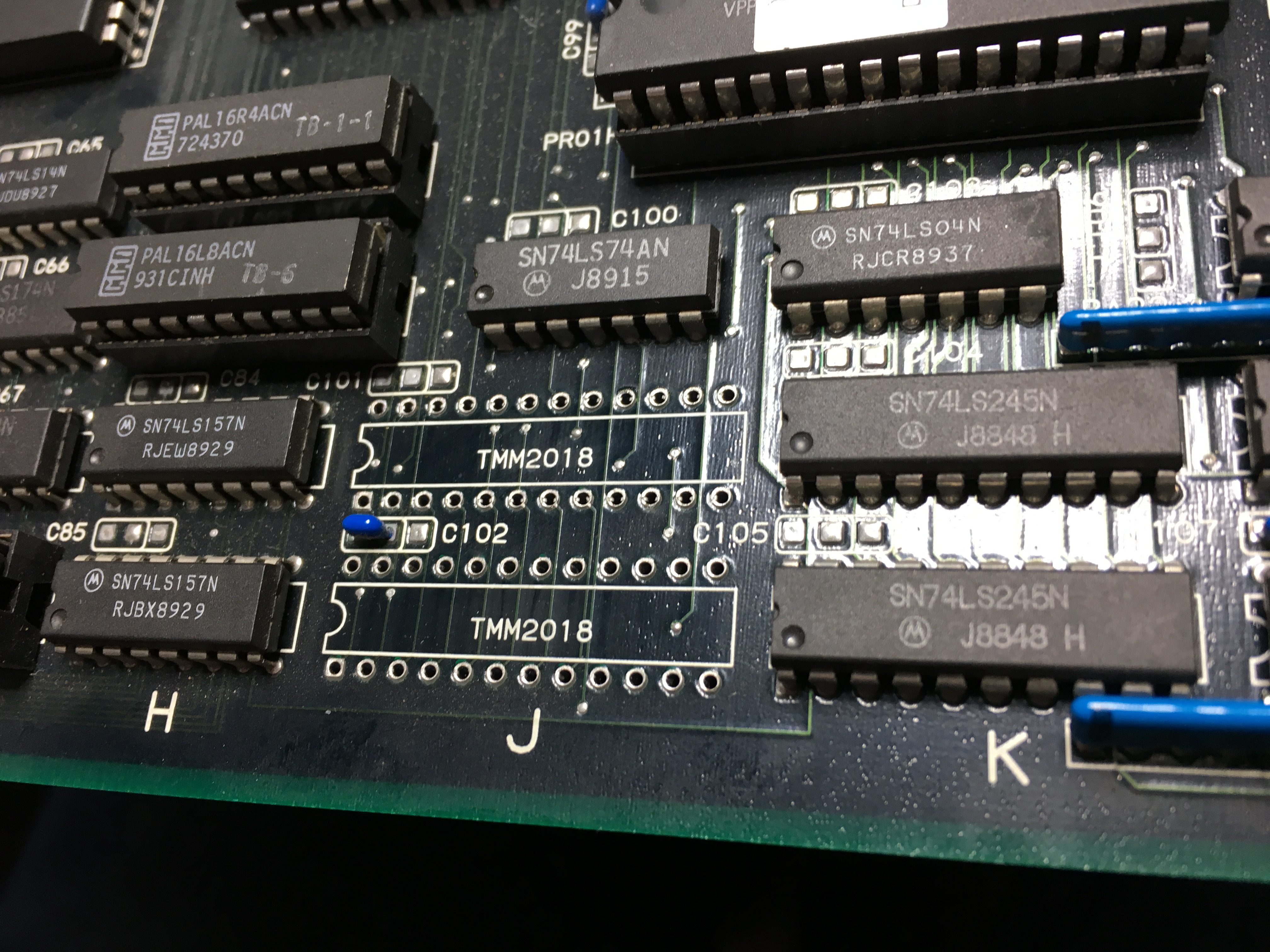
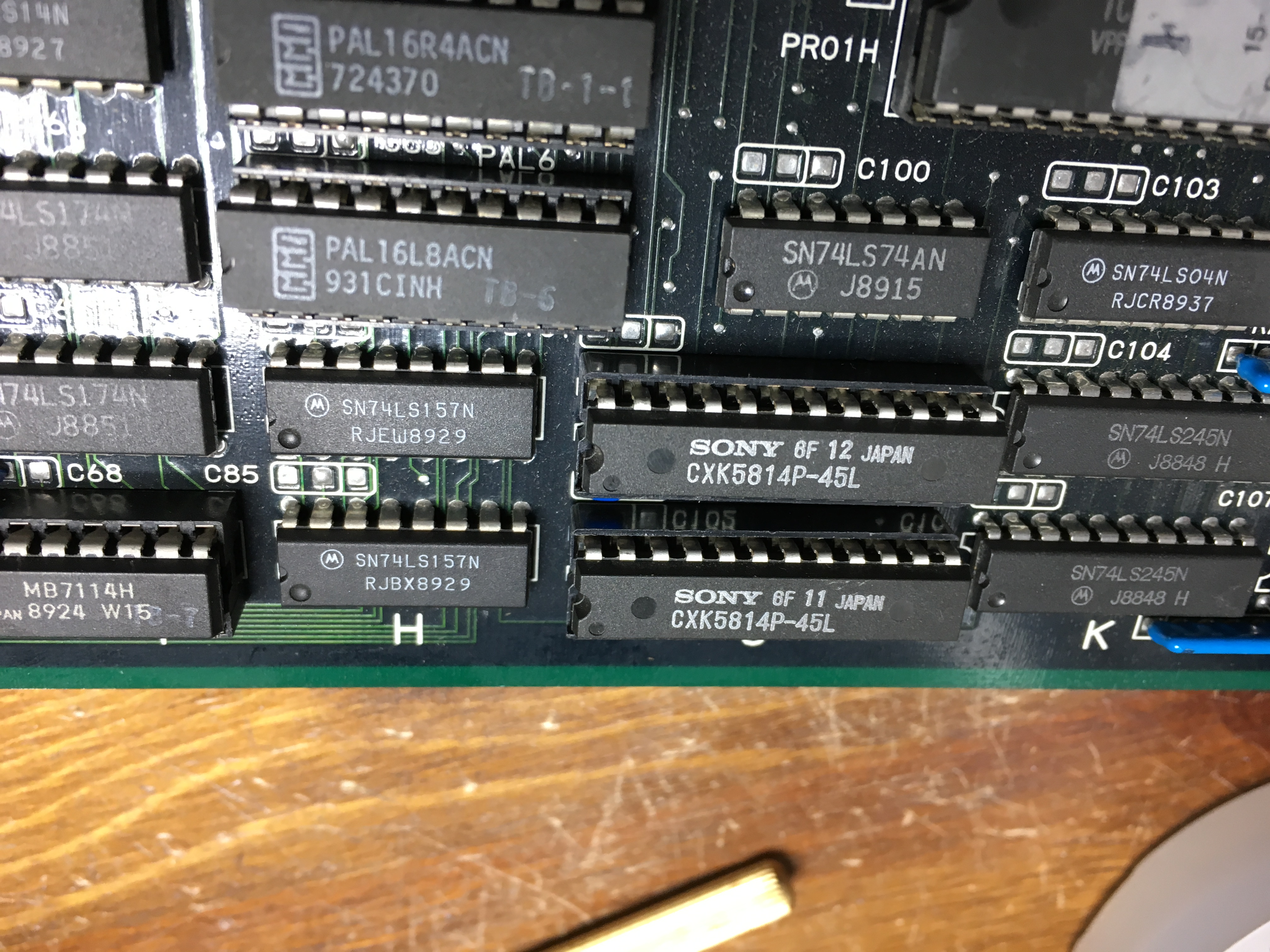
I eventually found a shorted capacitor at 
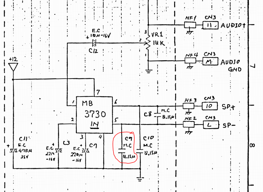
After replacing the capacitor the audio was loud and clear again. Job done 🙂


May 092018
 

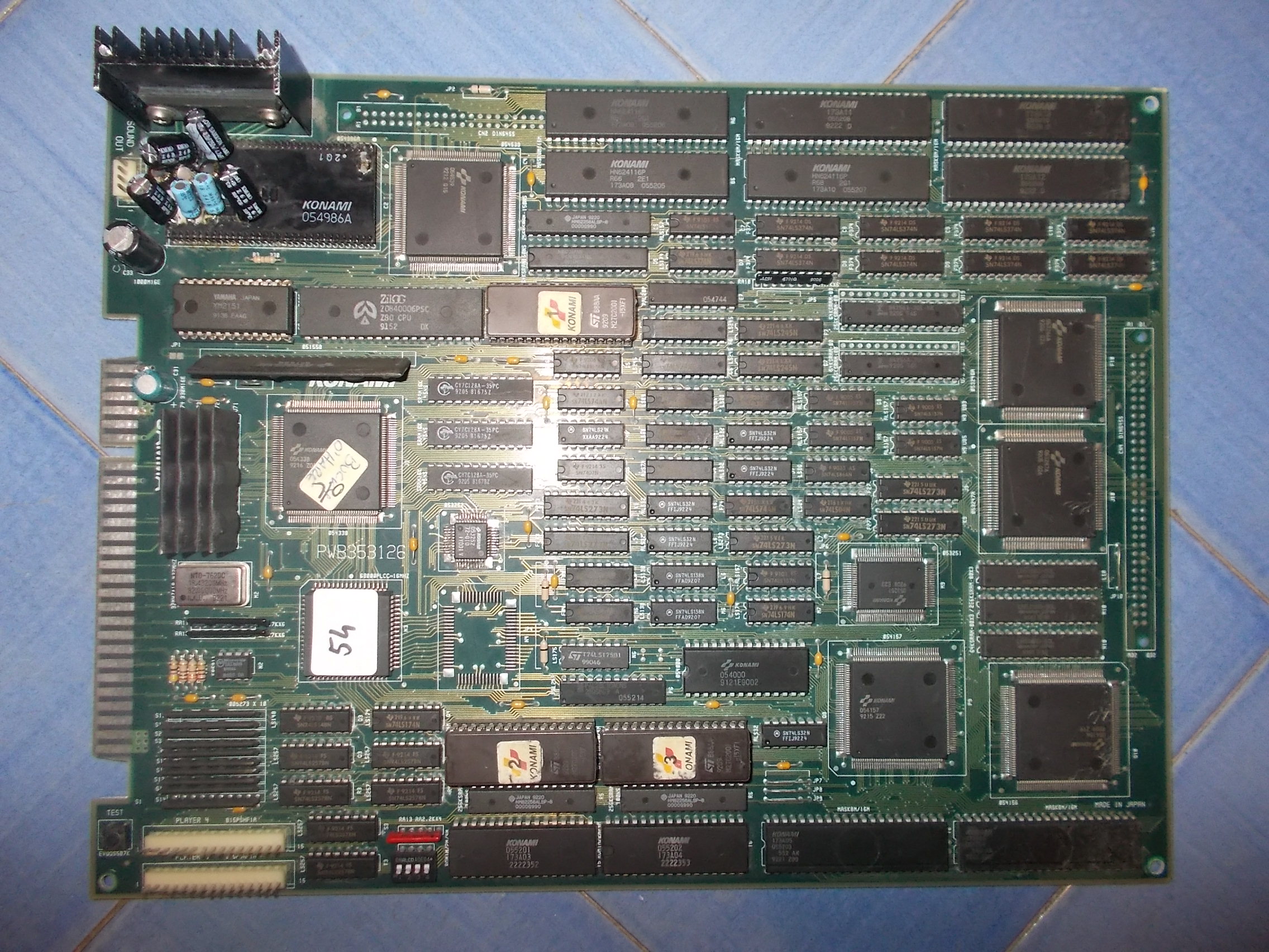
Received from Portugal this Bucky O’ Hare PCB for repair:

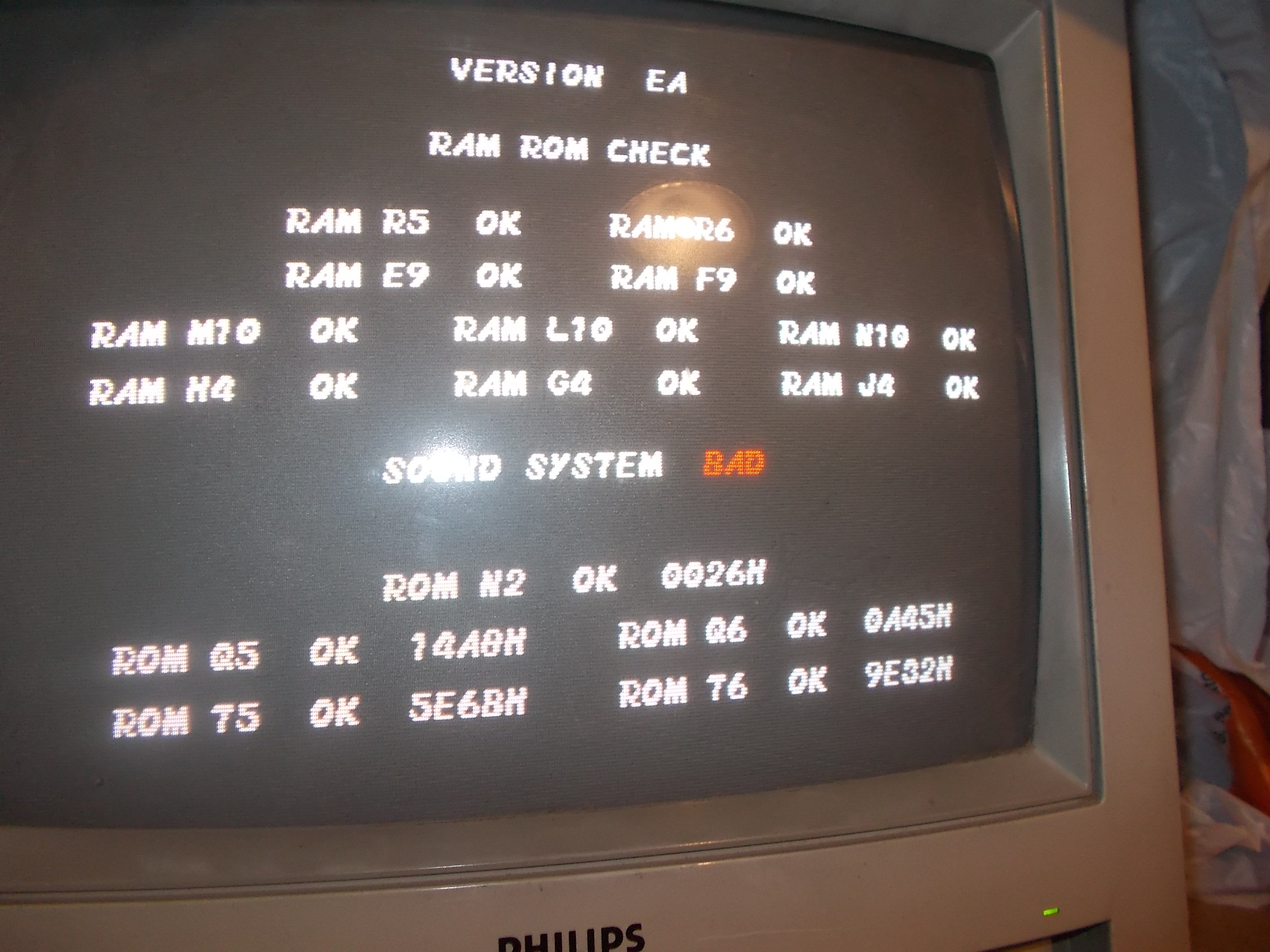
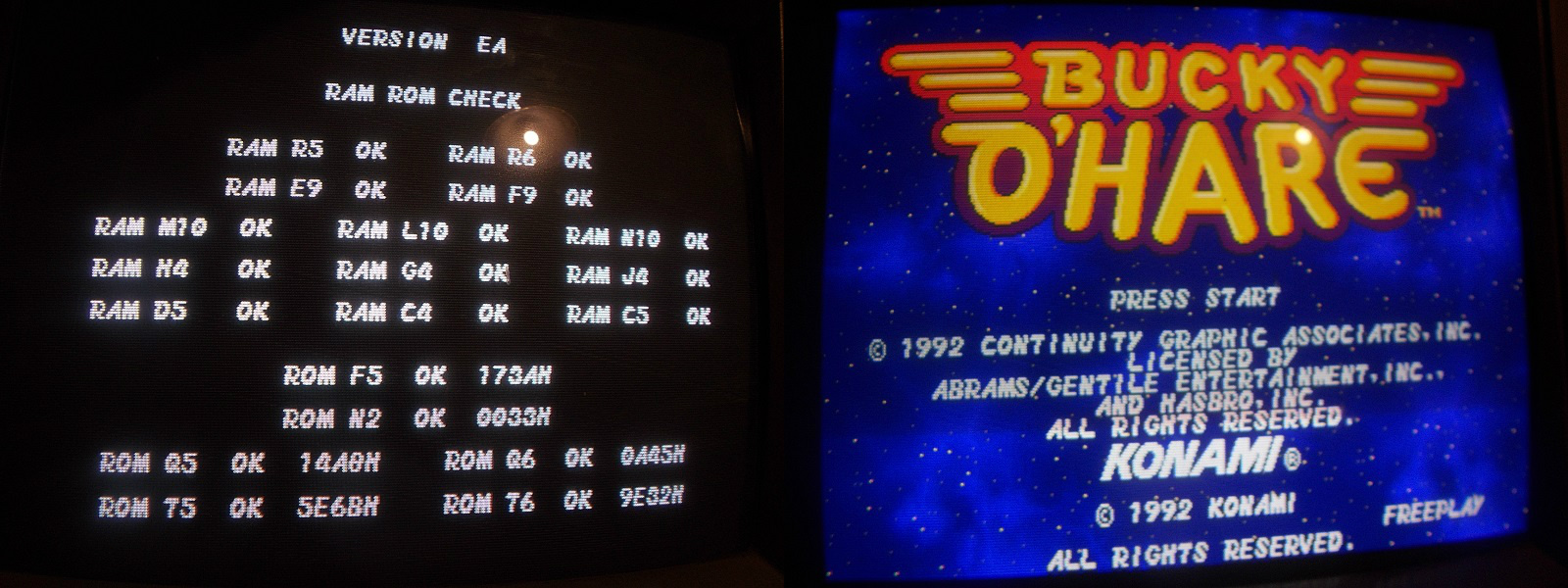
Board was failing the POST all the time showing a ‘SOUND SYSTEM BAD’ message

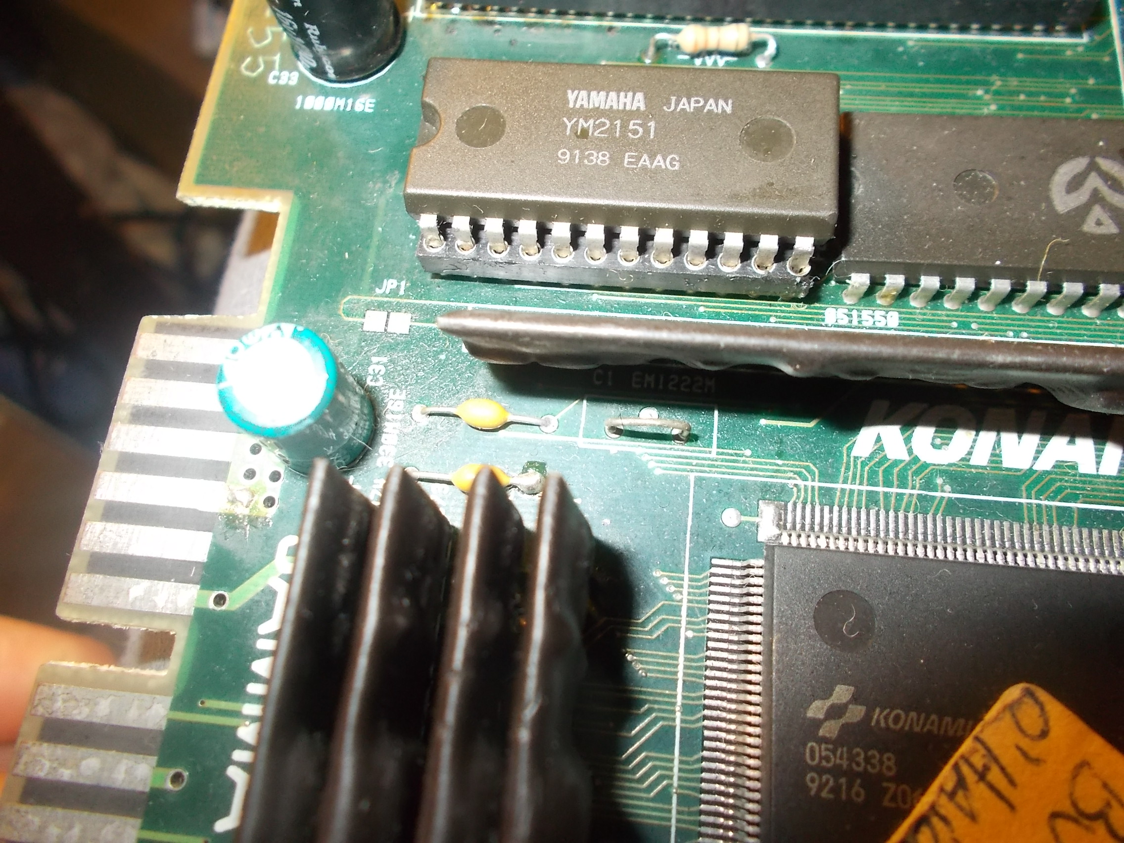
The sound system was previoulsy reworked : the YM2151 was socketed

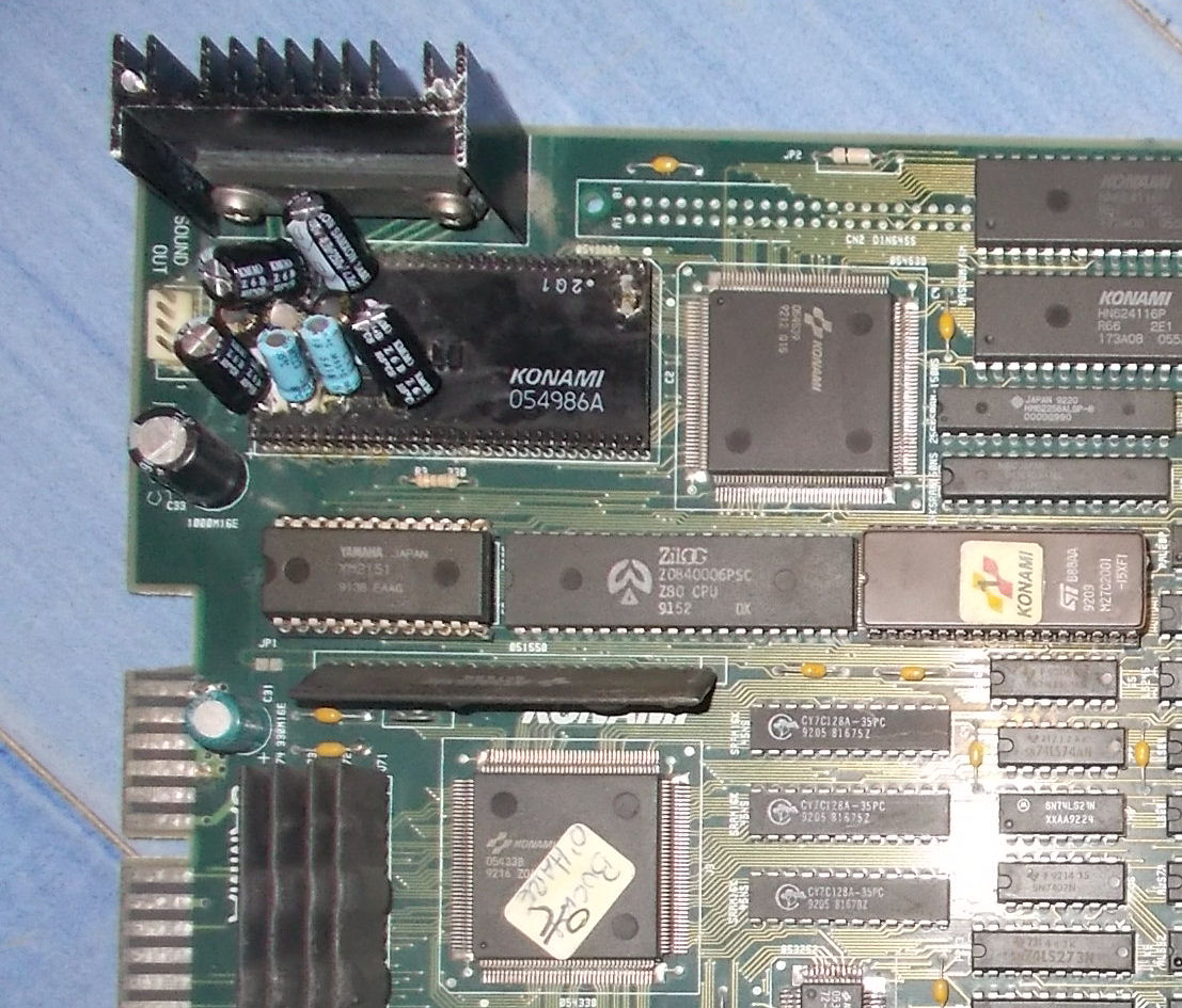
and the ‘054986A’ audio module had electrolytic capacitors replaced with thru-hole ones:

The solder side of the module showed signs of repairs too :

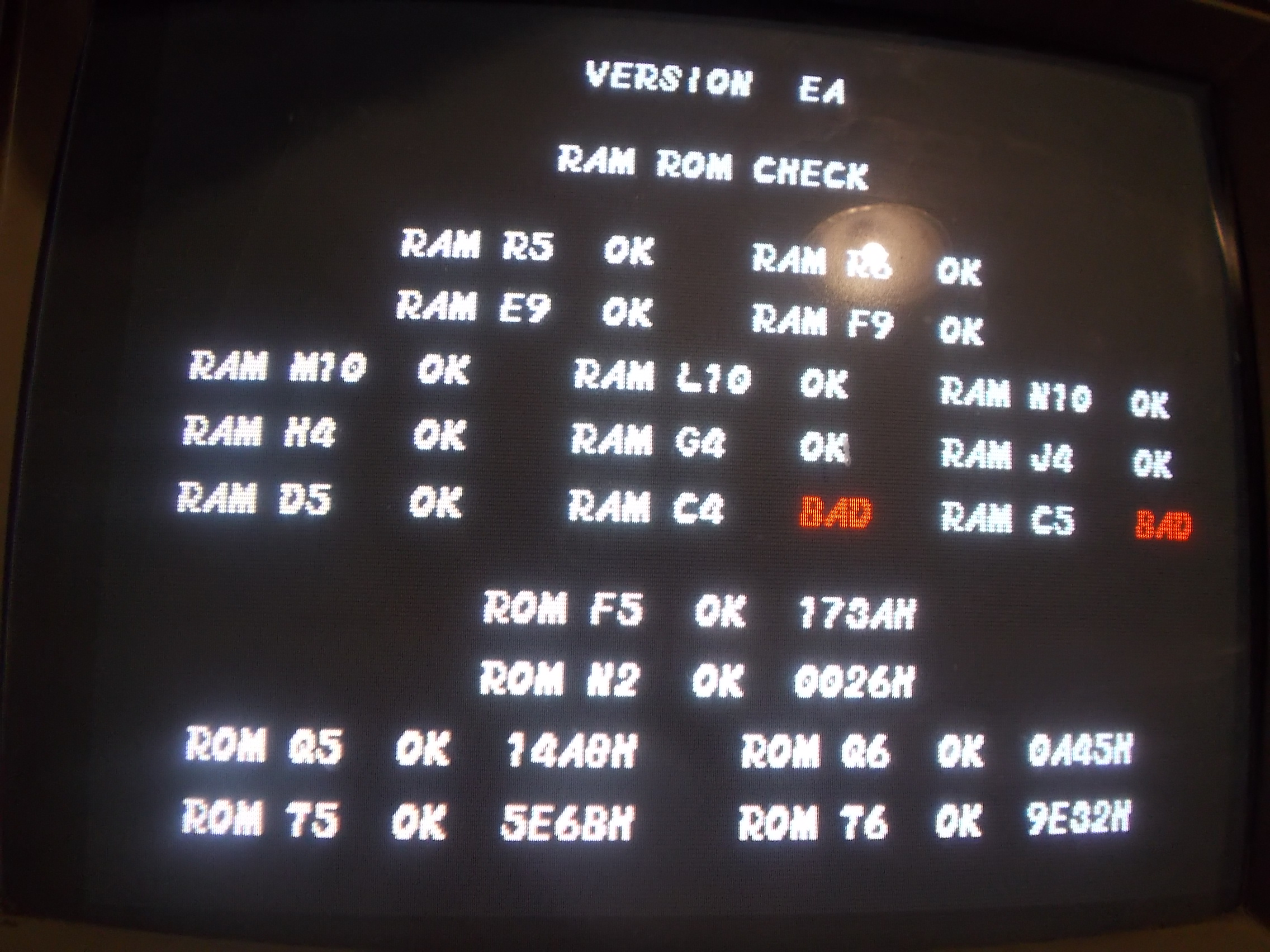
I suspected a broken trace underneath the module so I replaced it with a good one taken from a parts board.The error on POST changed to this :

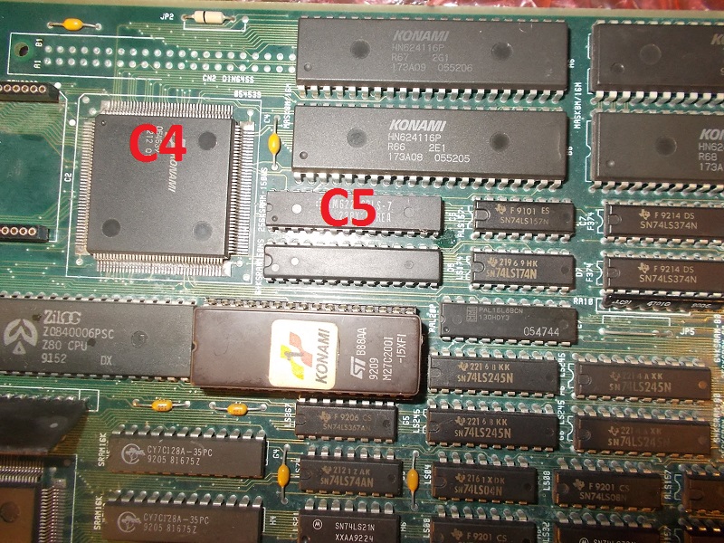
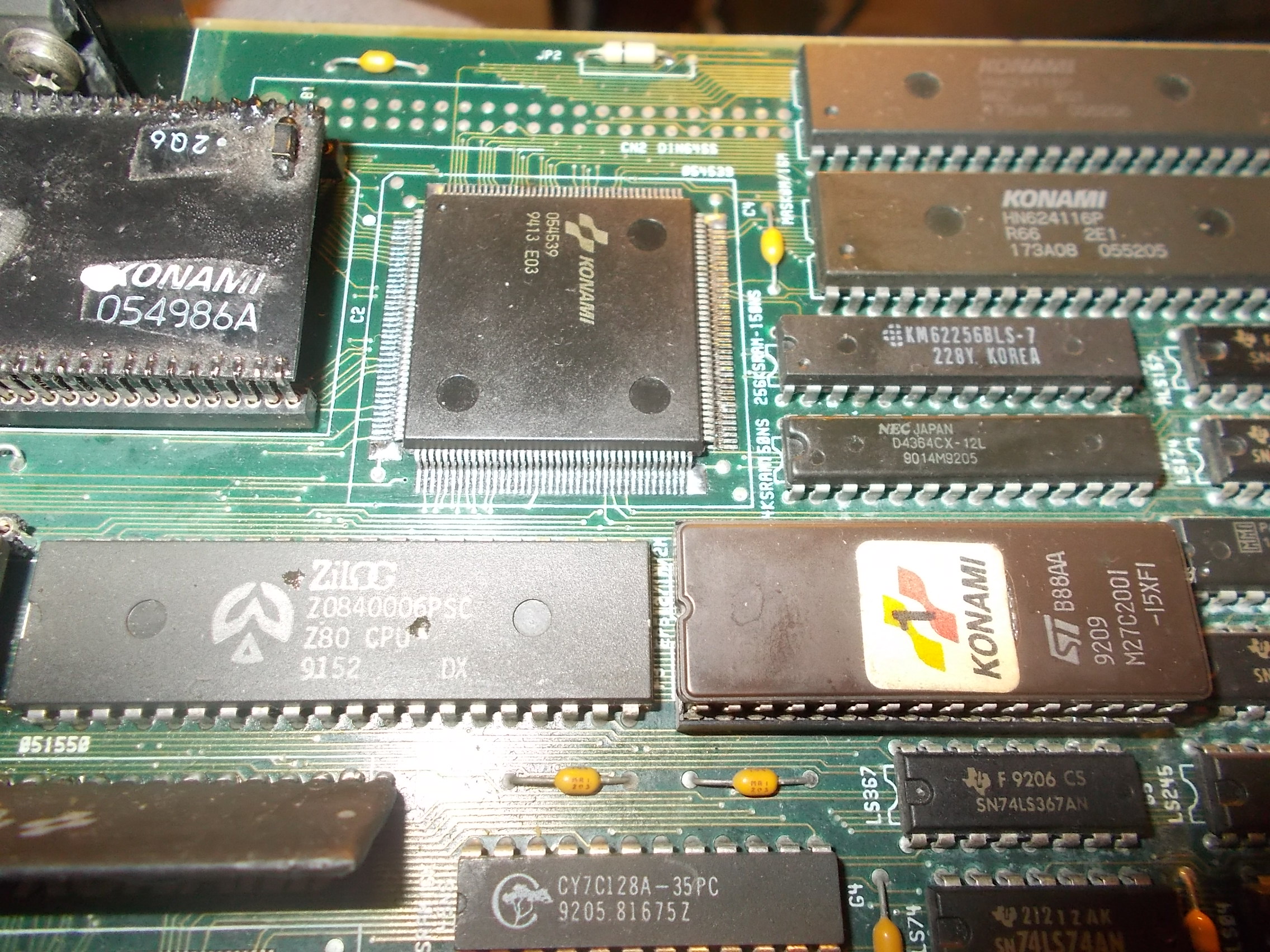
I looked at the board and found that actually the device @C4 is the custom ‘054539’ while the one @C5 is 32k x 8-bit SRAM (whose data/address bus is connected to the custom)

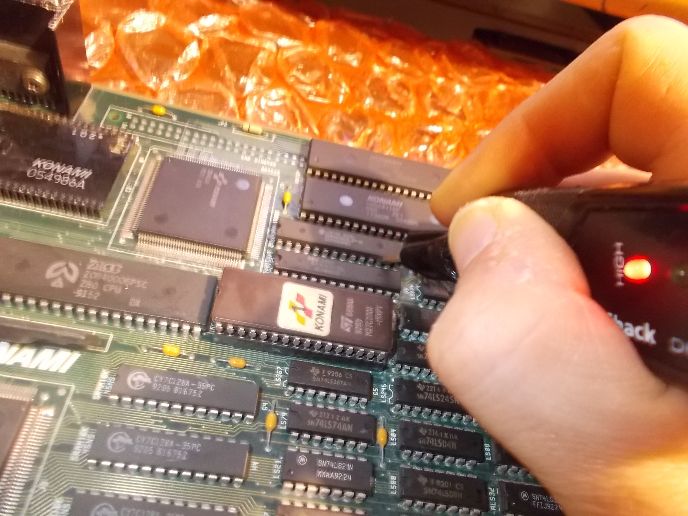
Probing the RAM revealed that data lines were all stuck high:

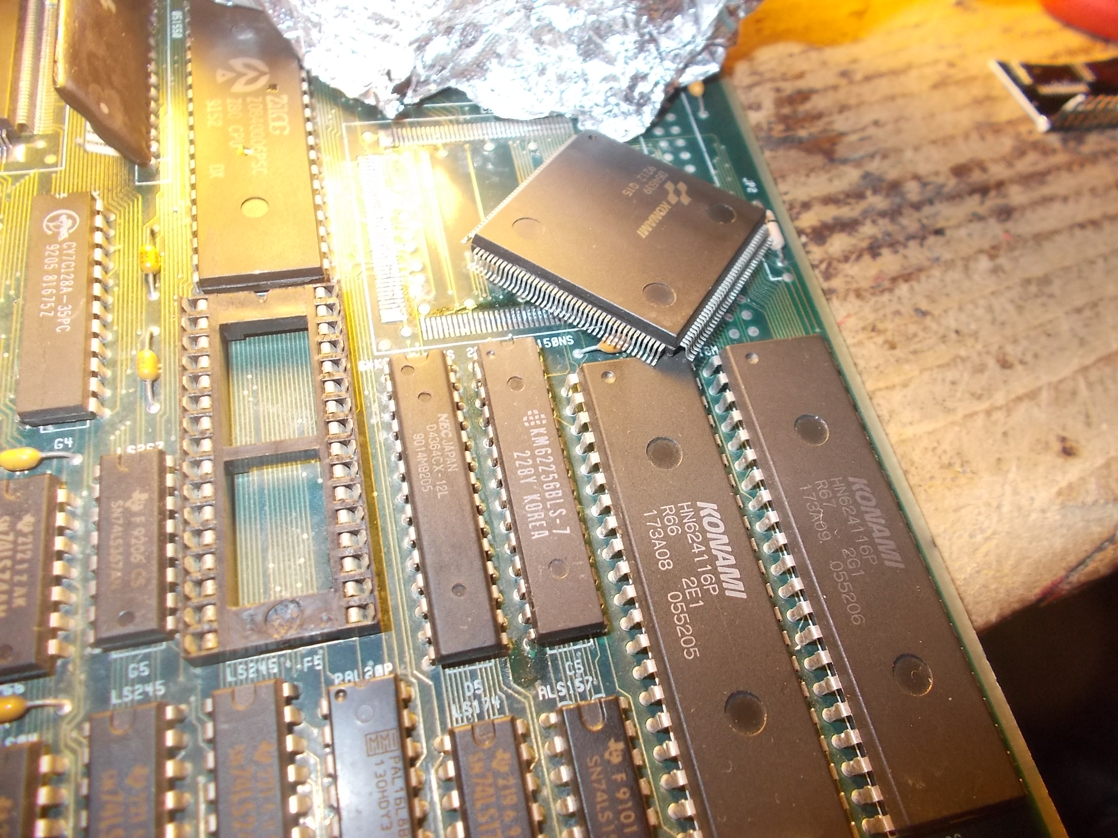
Piggybacking it had no effect so most likely the ‘054539’ ASIC was bad.I removed it:

Soldered back a spare :

Board booted up fine and entered in game with no further issues.Another repair accomplished.


 Posted by at 11:09 pm

Midnight Resistance repair log

 PCB Repair Logs  Comments Off on Midnight Resistance repair log
May 082018
 

I got this Data East – Midnight Resistance pcb from a friend.

He said that he dropped a ground wire onto the pcb by mistake and he thought it touched the pins on one of the L7B0072 custom ICs.

I booted the pcb and the game was running blind. Sounds and inputs was working fine, but a complete black image on the screen.

Been working on this hardware before, I knew that the palette RAM was located at J21 and J22, so I started checking their datalines with the scope

Hmm, zero activity

I then piggybacked a pair of new RAMs (6116 type) on top of the original RAMs

Voila, graphics are back 🙂

I then promptly desoldered the RAMs

and soldered a pair of sockets in their place. And the new RAMs

Job done 🙂
 

Wonder Boy repair log #2

 PCB Repair Logs  Comments Off on Wonder Boy repair log #2
May 072018
 

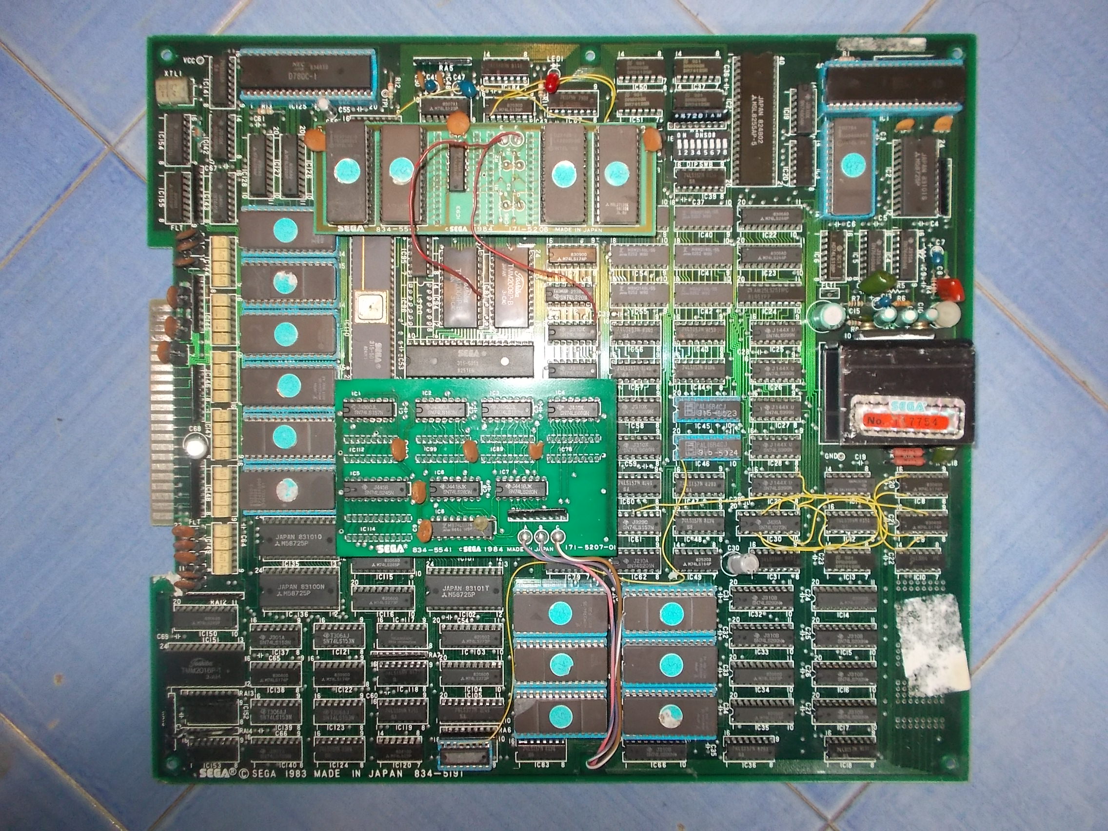
Received from USA this Wonder Boy PCB for repair, actually the board was a factory conversion on Sega System 1A hardware:

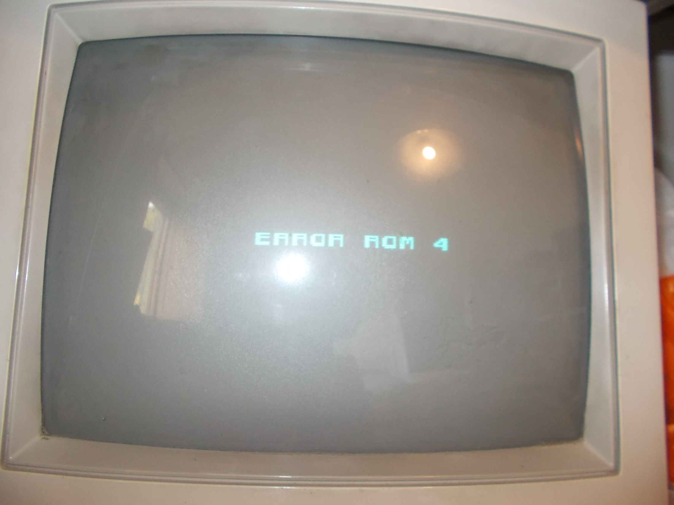
When powered it up I got most of times a steady black screen, rarely an ‘ERROR ROM 4’ message:

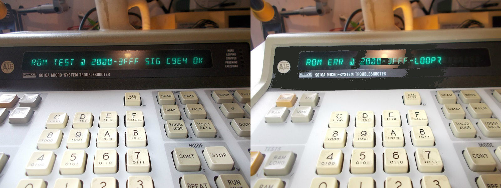
I fired up my Fluke 9010A to perform a ROM test.On some devices sometimes a valid signature was returned but more often I got error and a different signature :

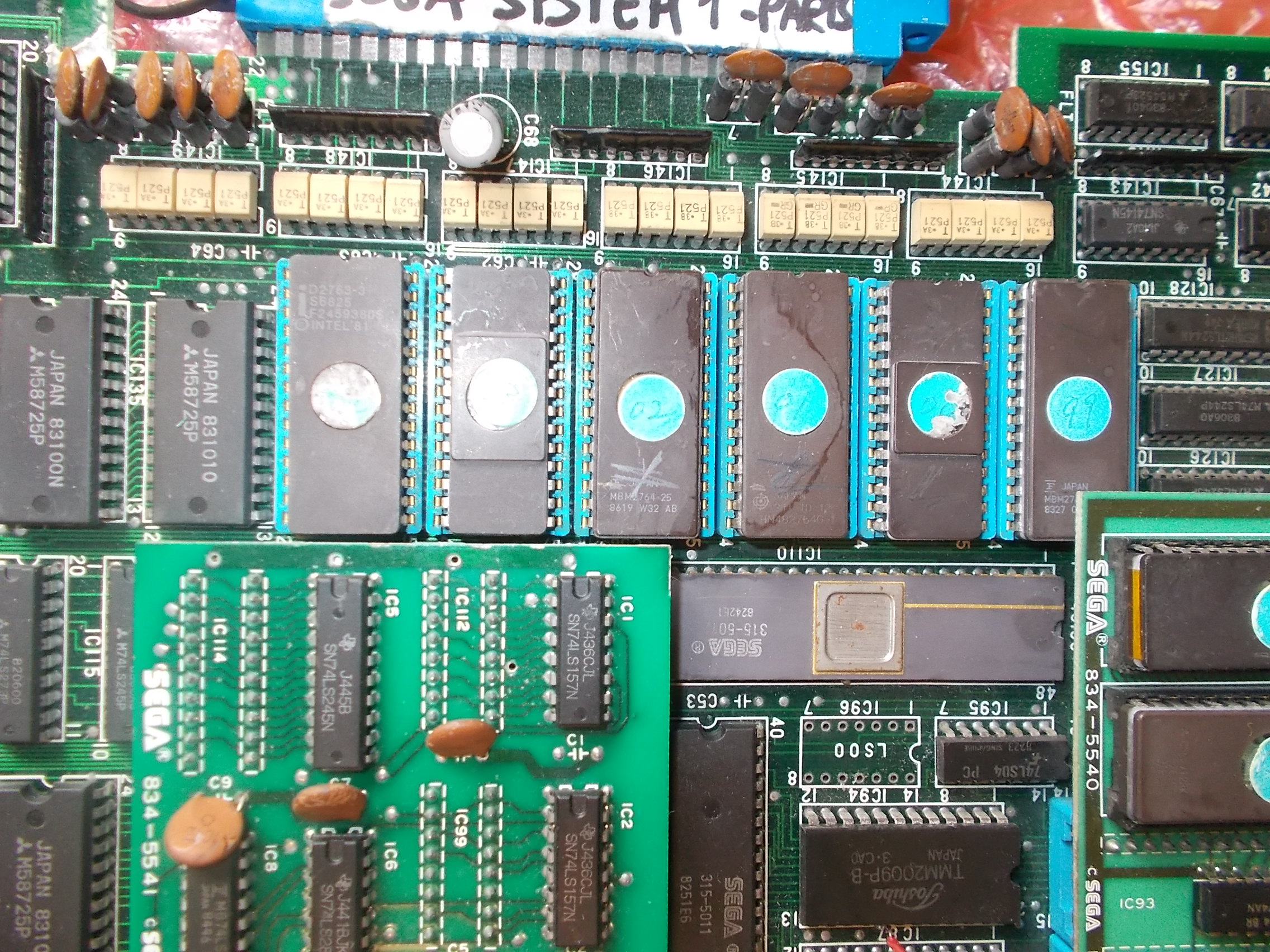
There are six program ROMs:

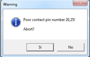
When I dumped them my programmer complained about some bad contact:

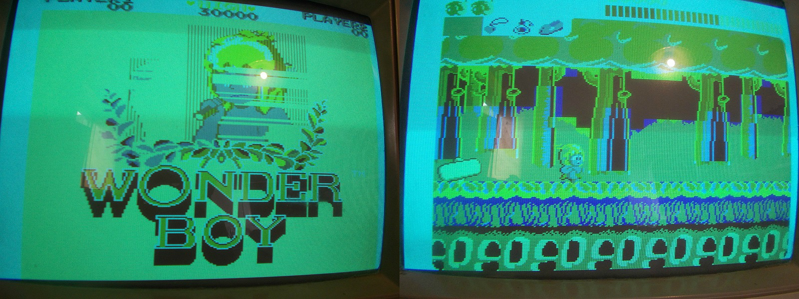
It turned out legs of some EPROMs were dirty and oxidized.After polished them the board booted up but  clearly a color was missing (the RED one) and GFX faults were present :

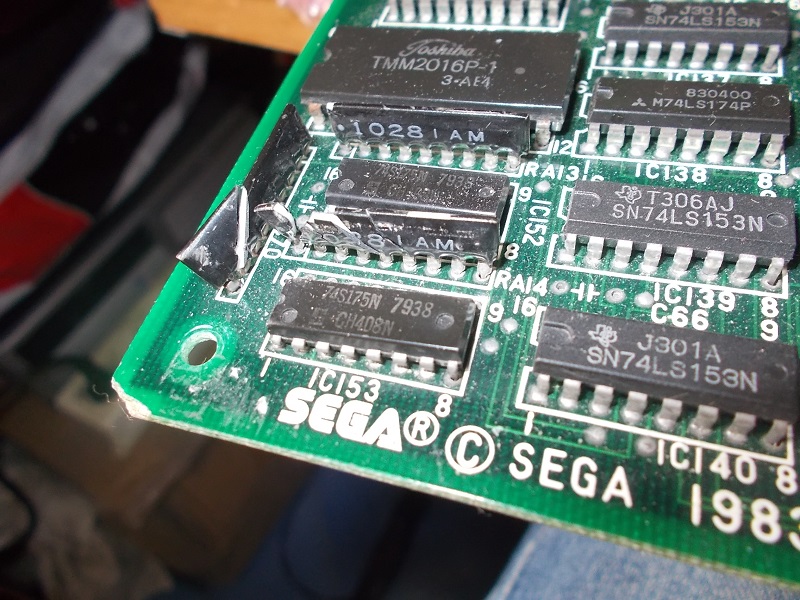
Doing a visual inspection I found a couple of broken 1K bussed resistor networks :

After checked connections I figured out they were used as resistor ladder in the palette circuit.I replaced them, this restored the three RGB colors and showed better the grahics faults:

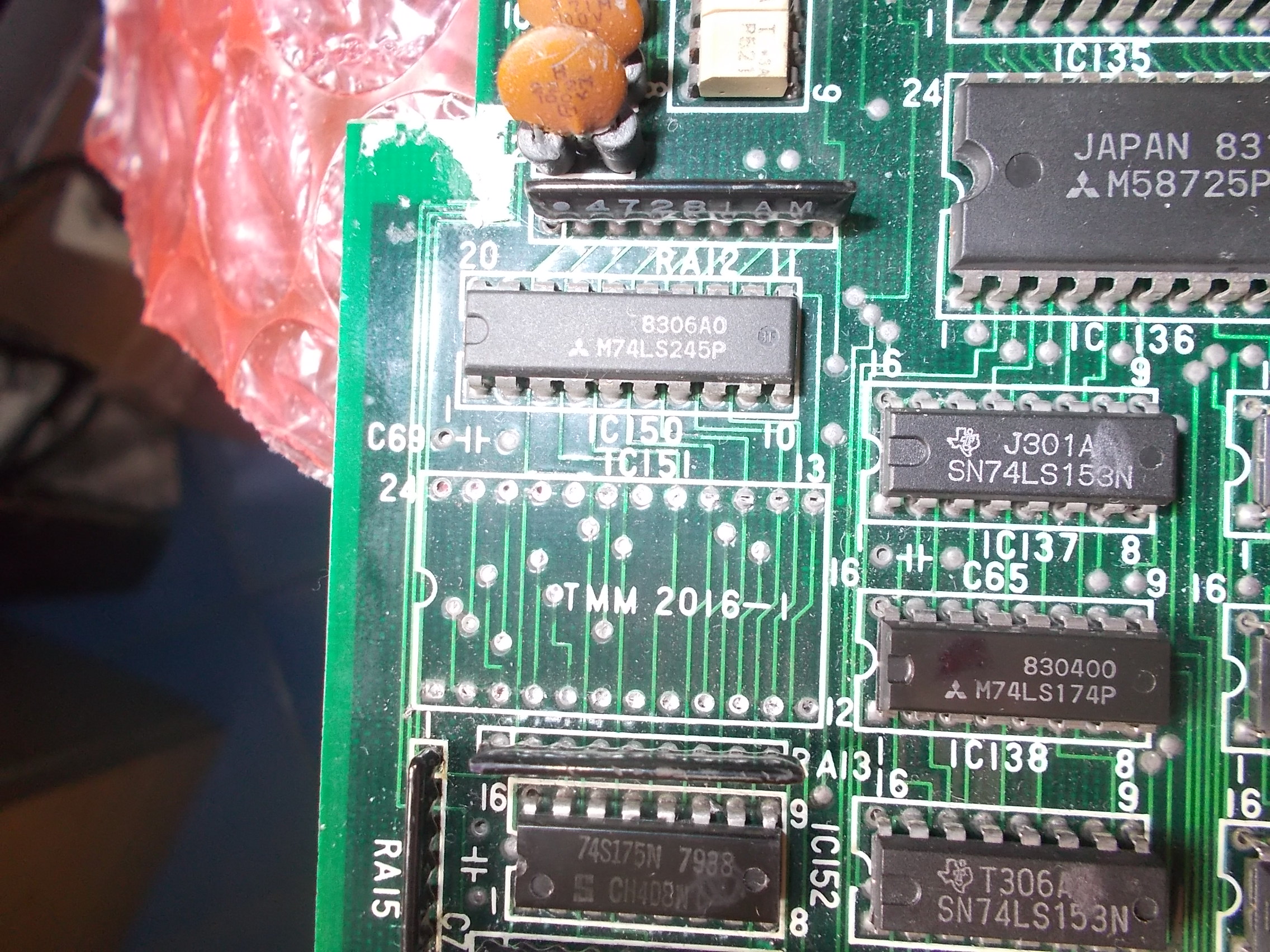
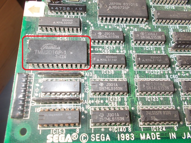
Backgrounds had wrong colors and some sprites (like main character) had missing parts and vertical lines through.As for first issue I went back to the color circuit where @IC151 lies a TMM2016 (8K x 8-bit) static RAM (whose data bits are routed to some 74LS175 flip-flop and finally converted to analog by the above mentioned resistor ladders)

Probing it revealed a unhealthy signal on an address line (A10 ,  pin 19), here’s a comparison with a good signal on the left:

Sure enough I removed the RAM :

Device failed the out-of-circuit testing:

Now the sprites issue.Relevant data is stored in four 27128 EPROMs installed on a small piggyback board:

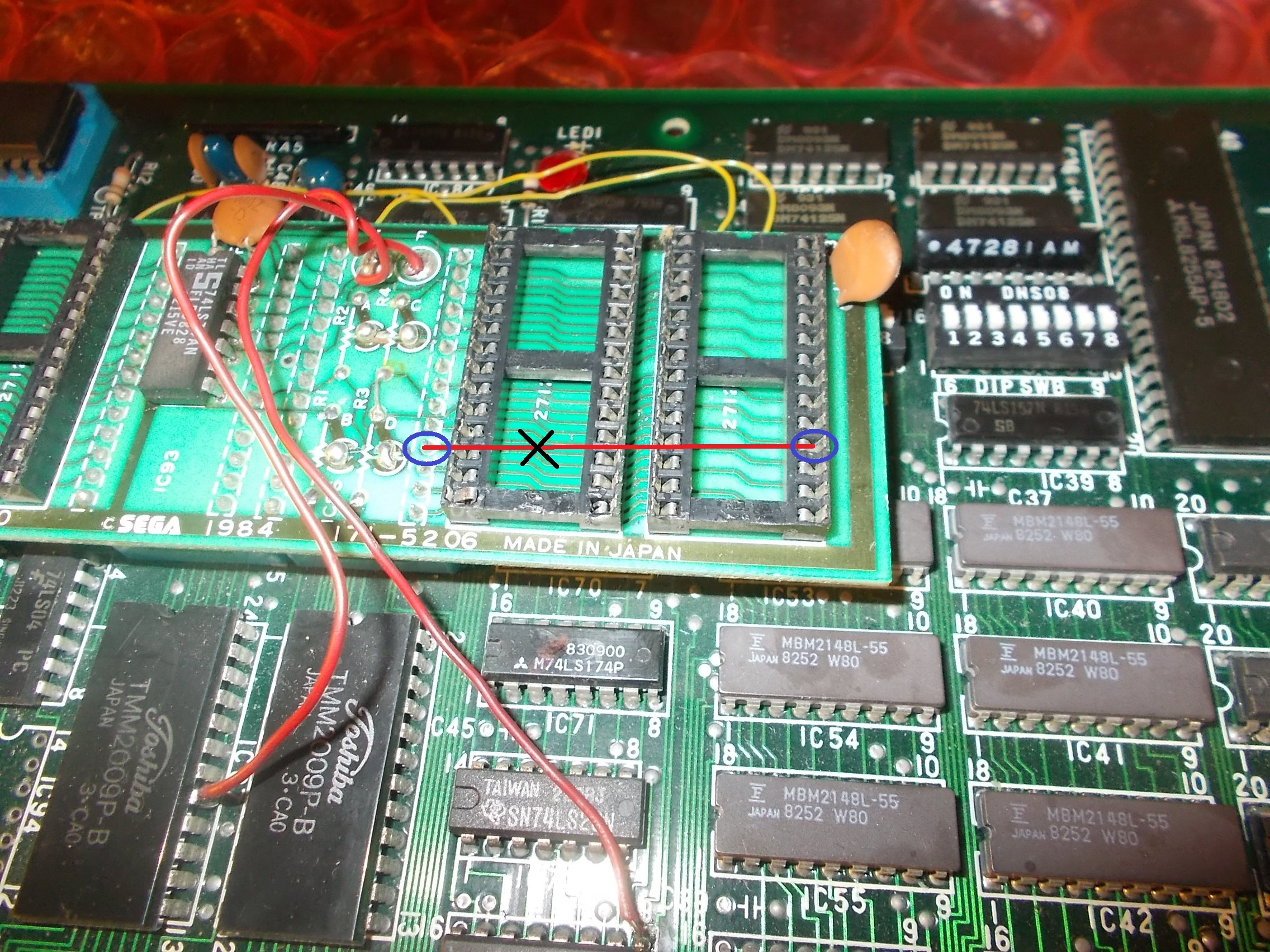
Devices were dumped as good.After a quick check with my multimeter I found a missing connection between a data line of a ROM and the header which goes into the sockets :

I restored the connection and this fixed board completely.Another repair accomplished.

 Posted by at 9:26 pm

Michael Jackson’s MoonWalker repair log #3

 PCB Repair Logs  Comments Off on Michael Jackson’s MoonWalker repair log #3
May 052018
 

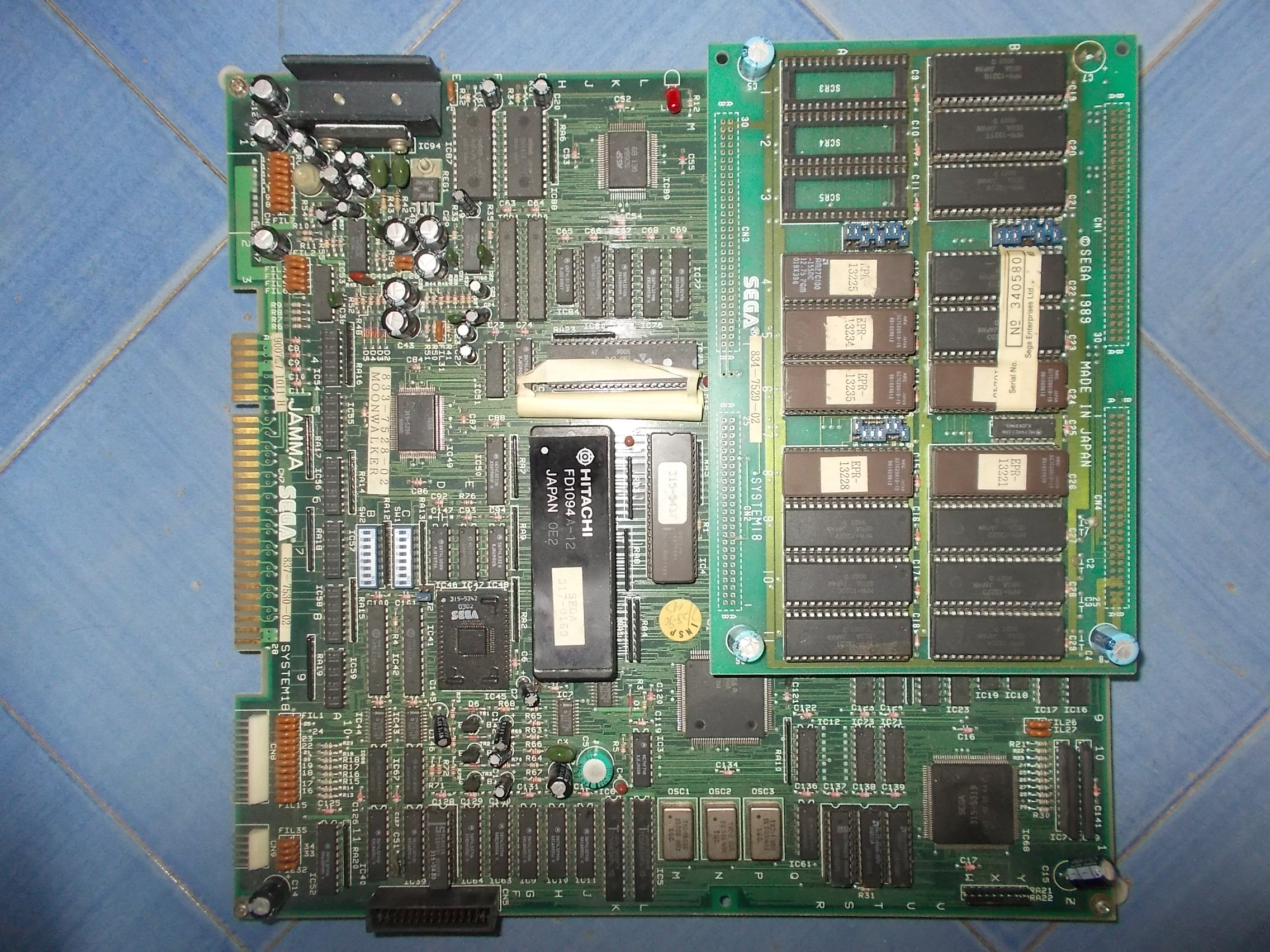
Received from UK this Michael Jackson’s MoonWalker PCB (Sega System 18 hardware)

Board gave a steady black screen on power up, no sign of activity on main CPU busses.I transfered on a same board of mine the FD1094 module along with the 8751 MCU and they worked fine.I used my ROM board but still no boot so I came to the conclusion that fault was located on motherboard.Looking for WORK RAMs and I found them :

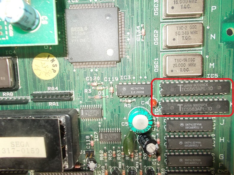
Two Toshiba TC5563 (8K x 8-bit static RAMs) which means high unreliability and chance of failure.I piggybacked a good chip on the one @IC5 and board booted into game:

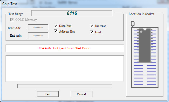
RAM obvioulsy failed when tested out-of-circuit:

As said board booted up now but most of the sprites were wrong:

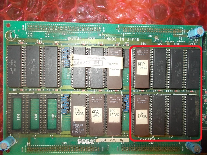
Relevant data is stored into eight 2Mbit devices (mostly MASK ROMs) located on ROM board:

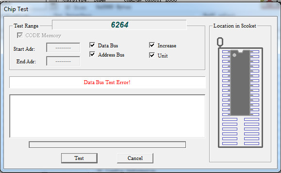
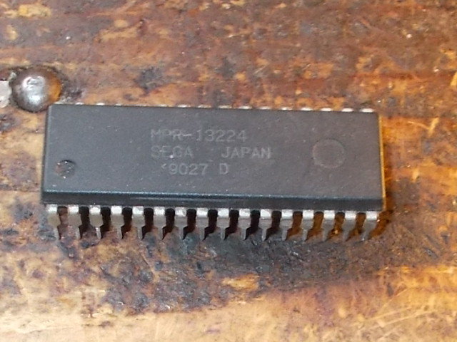
I dumped them and they all matched the MAME set except the one @B11 :

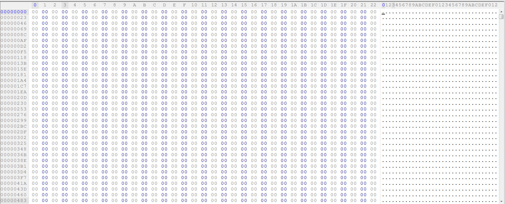
Opening the dump in an HEX editor revealed it was empty:

So device was bad.I burned a 27C020 EPROM with MAME dump, this restored the correct sprites and fixed board completely.Job done.

 Posted by at 5:03 pm