Terra Cresta repair log #4

 PCB Repair Logs  Comments Off on Terra Cresta repair log #4
Oct 042018
 

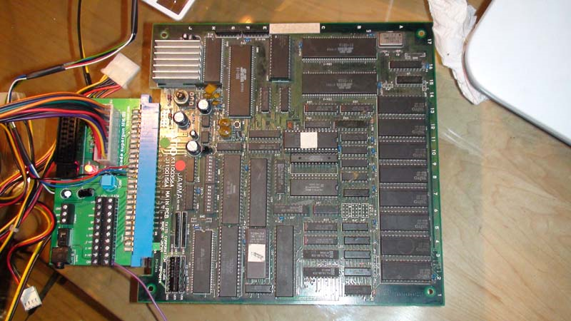
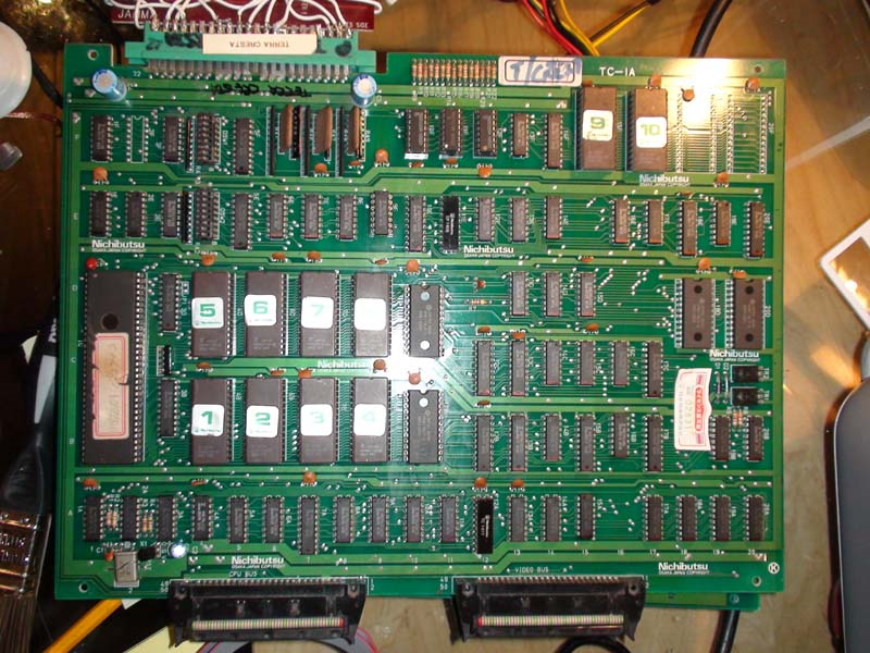
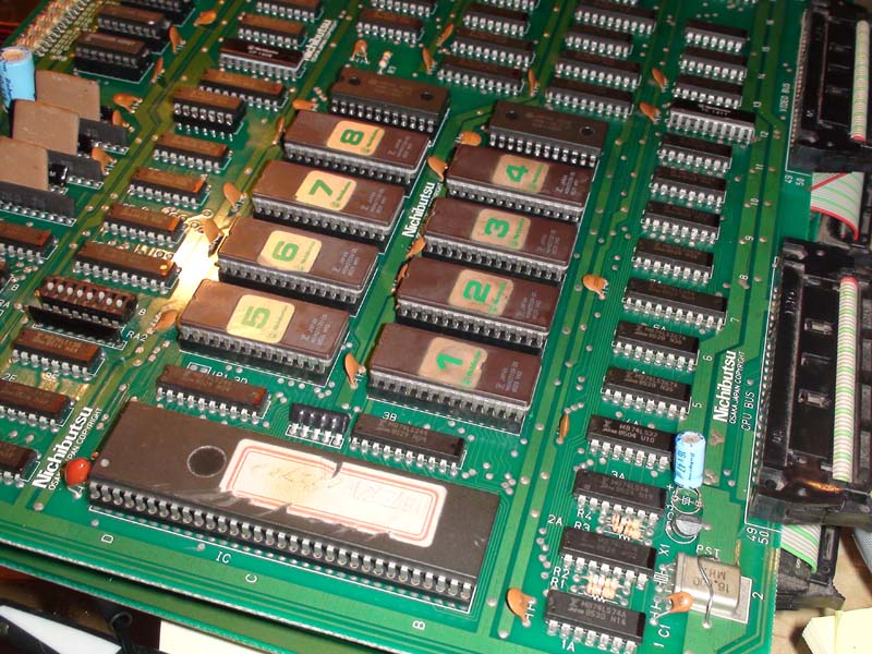
Another on my pile that has been wanting attention for a while. It is an original PCB and is the YM2203 version unfortunately, much prefer the YM3526 version with superior soundtrack.

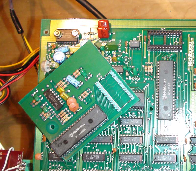
Which version you have is easily identified by a daughterboard (YM2203) on the underside of the PCB.

Symptoms

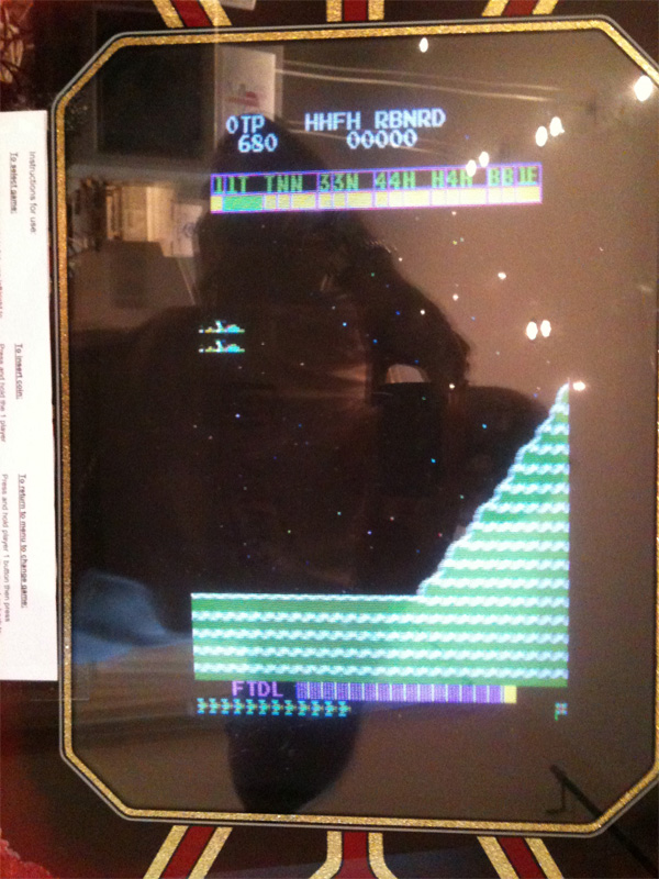
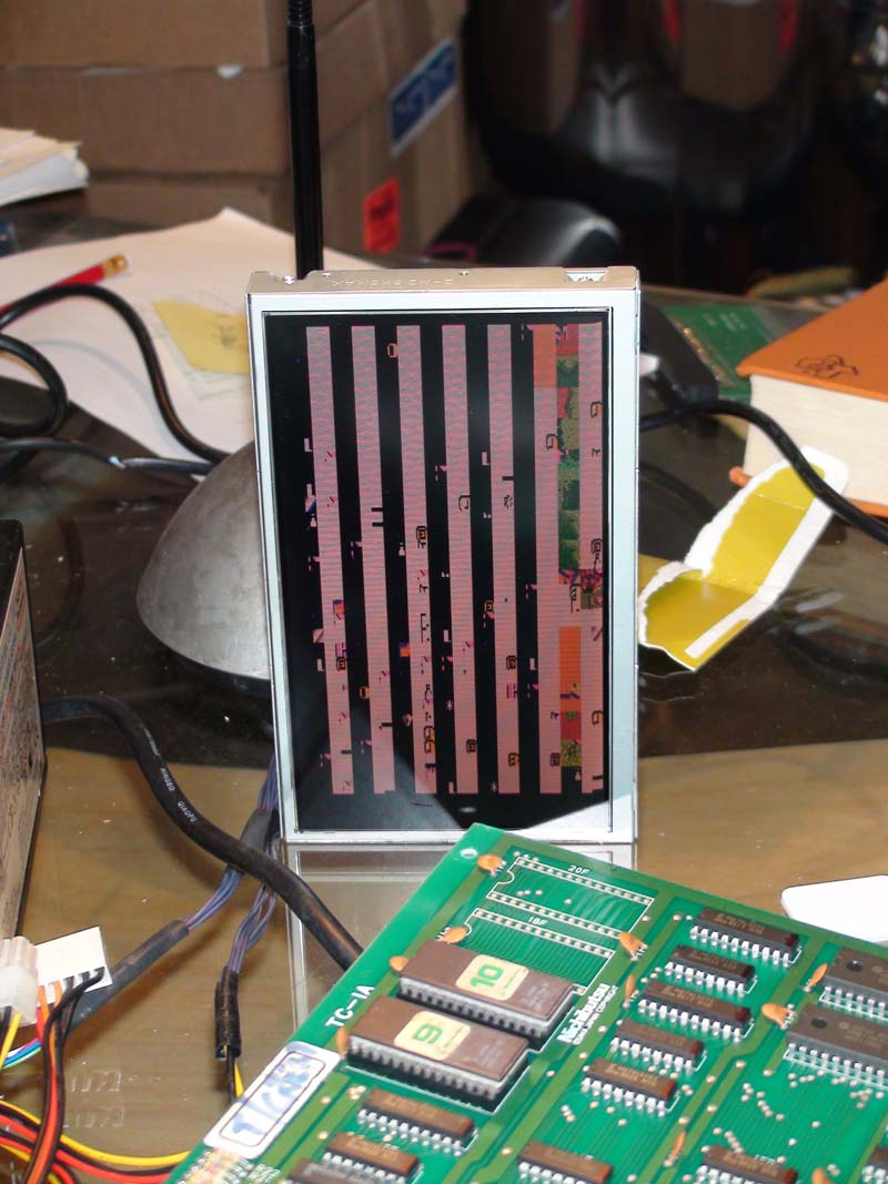
PCB will not run at all, all I get on the screen is static garbage which is always the same whenever I try to boot.

I started by looking at the clock circuit, I did this by checking the 68000 CPU’s Clock (CLK) pin which was pulsing as I expected, so the clock circuit must be good. The next thing to check was the RESET pin on the CPU which should have been HI, but it was LO and stayed LO, which mean’t no watchdog system was barking. Pin should have flipped to LO for a split second on boot and stayed on HI for an enabled CPU.

I probed further and checked the HALT pin on the CPU, which was LO, this told me there is a Bus error somewhere and the CPU has put its handbrake on.

Next thing to do was verify the CPU program ROMS (1, 2, 3, 4, 5, 6, 7 & 8 ROMs) were good, as there is no point checking the PCB any further if it has nothing worth running. They all checked out good.

Next I checked the CPU buffers (74LS244), which were inactive as I expected but checked out good.

Ok I thought, must be the CPU RAM (6116) which is bad at locations 10b and 10d, I checked them but they were inactive as I expected, so desoldered them to test them. They both checked out good.

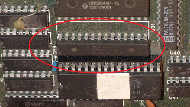
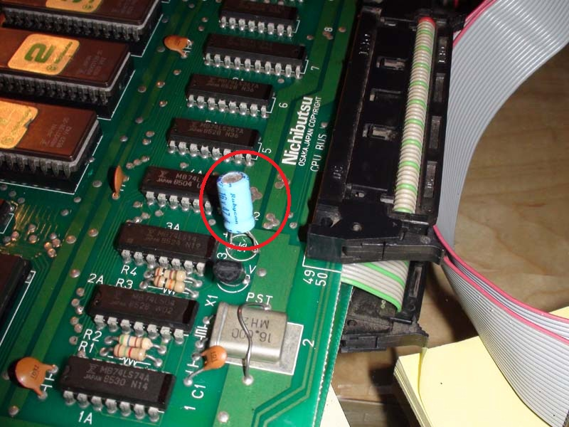
Hmm….at this point I had checked all components on the PCB which would stop the CPU running. I probed further and started to check the Caps. I found a Cap which when I checked both poles with my logic probe, it showed LO for both poles instead of LO (-) and HI(+) which I expected. This can only mean the Cap is shorted. I checked again with a Multimeter which confirmed this.

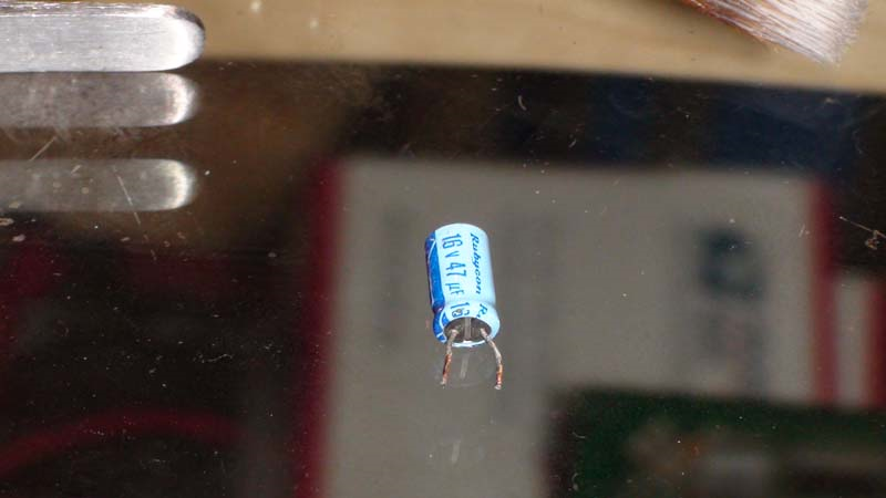
Off it came;

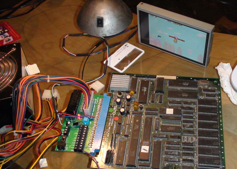
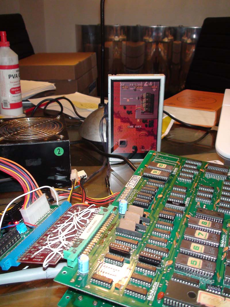
I soldered in a new Cap and the game came right up!

However, I was not finished yet! Time to convert this YM2203 PCB to a YM3626 version.

First, I removed the daughterboard, you can see the large YM2203 IC on the daughterboard with the Nichibutsu markings on it. The other large Nichibutsu on the PCB is the Z80A for the games sound and soundtrack. Was this an attempt by Nichibutsu to disguise these non-custom components?

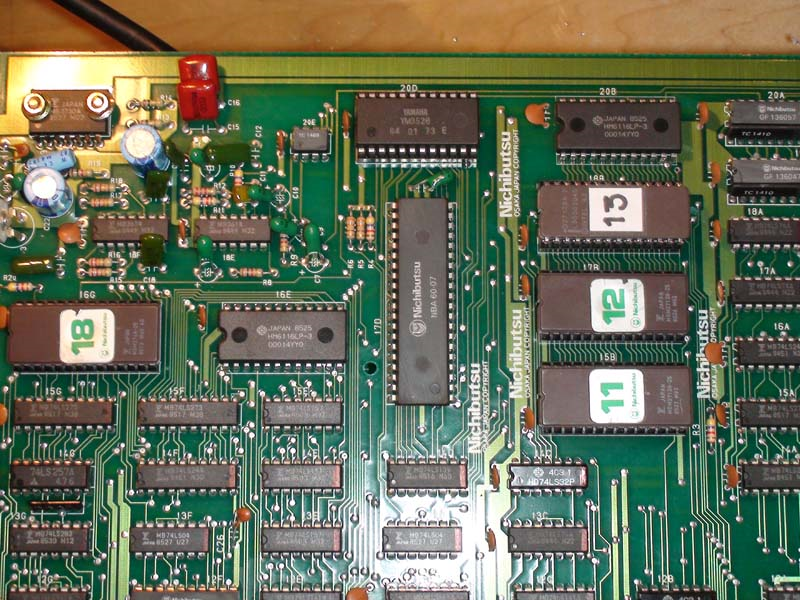
Then we need to reburn ROMs 11(15b) & 12(17b) with the sound code from the YM3526 version of the game from MAME. Also, we need to introduce ROM 13(18b).

Next, seat the YM3526 IC where the daughterboard once was;

Job done!
Atari Missile Command repair log

 PCB Repair Logs  Comments Off on Atari Missile Command repair log
Oct 042018
 

I was recently given a Missile Command to look at for a friend.

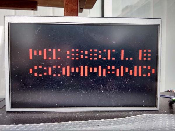
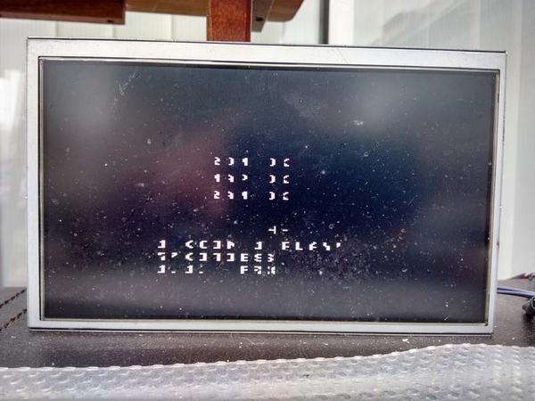
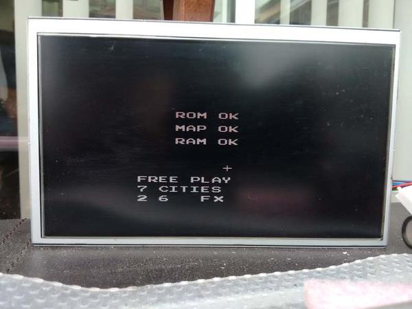
Upon firing up the PCB on the bench, all I got was a white screen and the Self Test showed no display but did report a bad RAM which I replaced at M4.

Now the Self Test was reporting a bad RAM at J4, which I also replaced.

No Change.

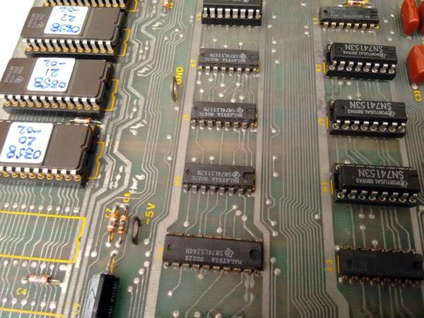
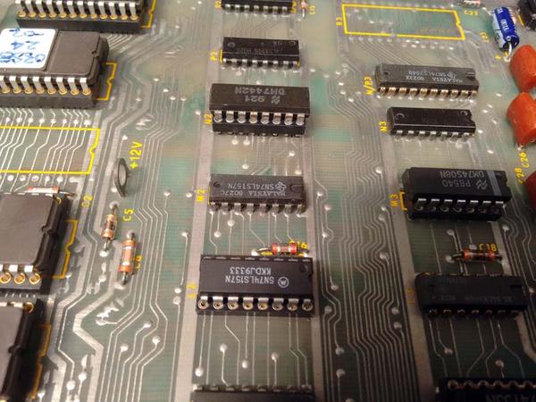
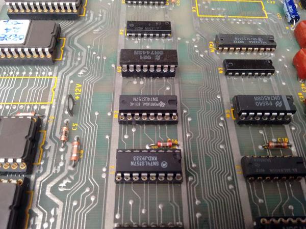
So, I probed around and found that the LS157 at H2 had stuck outputs.

This was replaced;

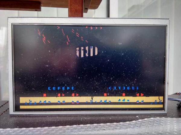
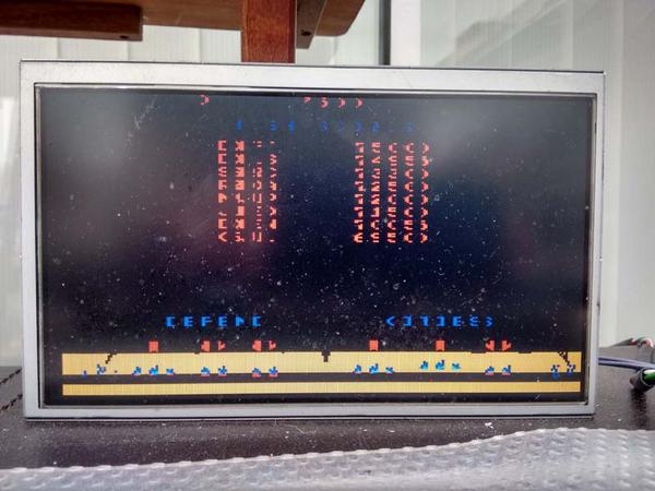
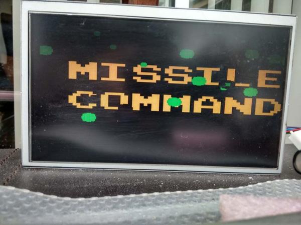
The PCB was now running but with graphical issues;

After alot of head scratching and probing, my attention turned to the DRAM controller section.

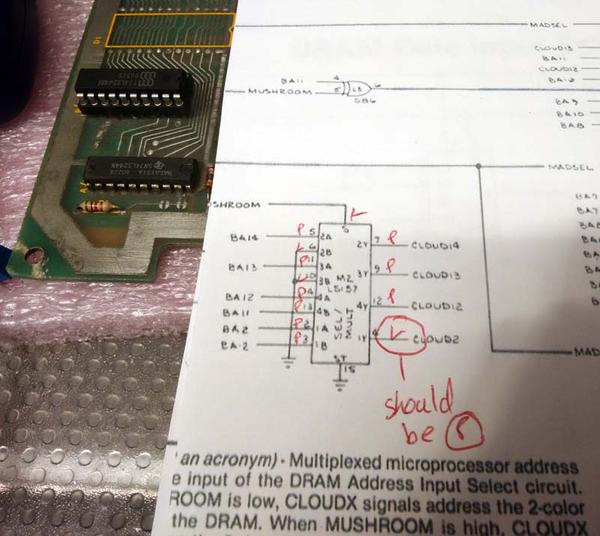
Here, I looked at another LS157 at M2, which seemed to be working except the output pin 4 (CLOUD2) was stuck LO. Surely this should be pulsing?

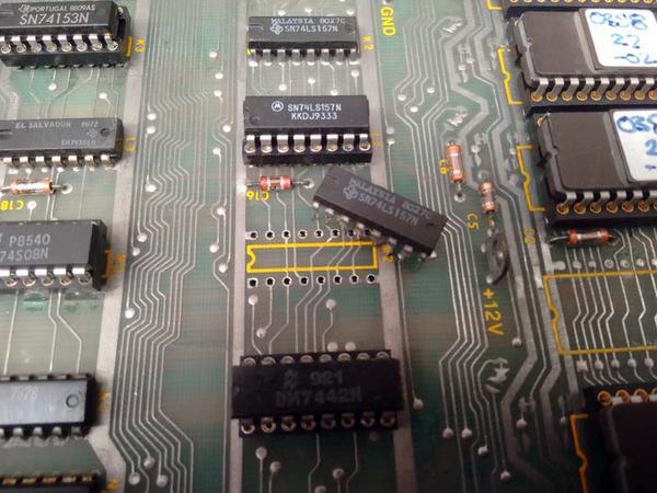
I tried to piggyback another LS157 over the suspected failed LS157, but it had absolute no effect.

So I dug out my HP Comparitor to check it out

Also showing pin 4 as bad, looks like this could be the culprit.

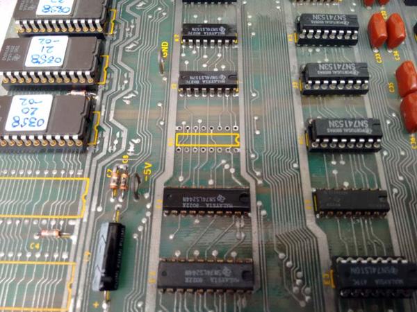
M2 was duly removed;

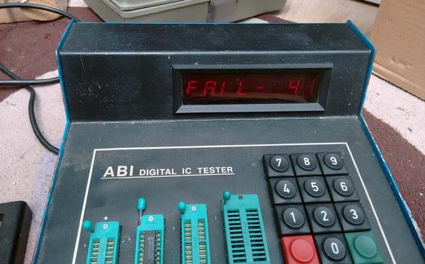
I also tested it in a TTL tester to verify;

Replaced with fresh LS157;

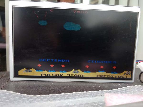
Switch on;

Now fully working.

Double-Wings repair log

 PCB Repair Logs  Comments Off on Double-Wings repair log
Oct 042018
 

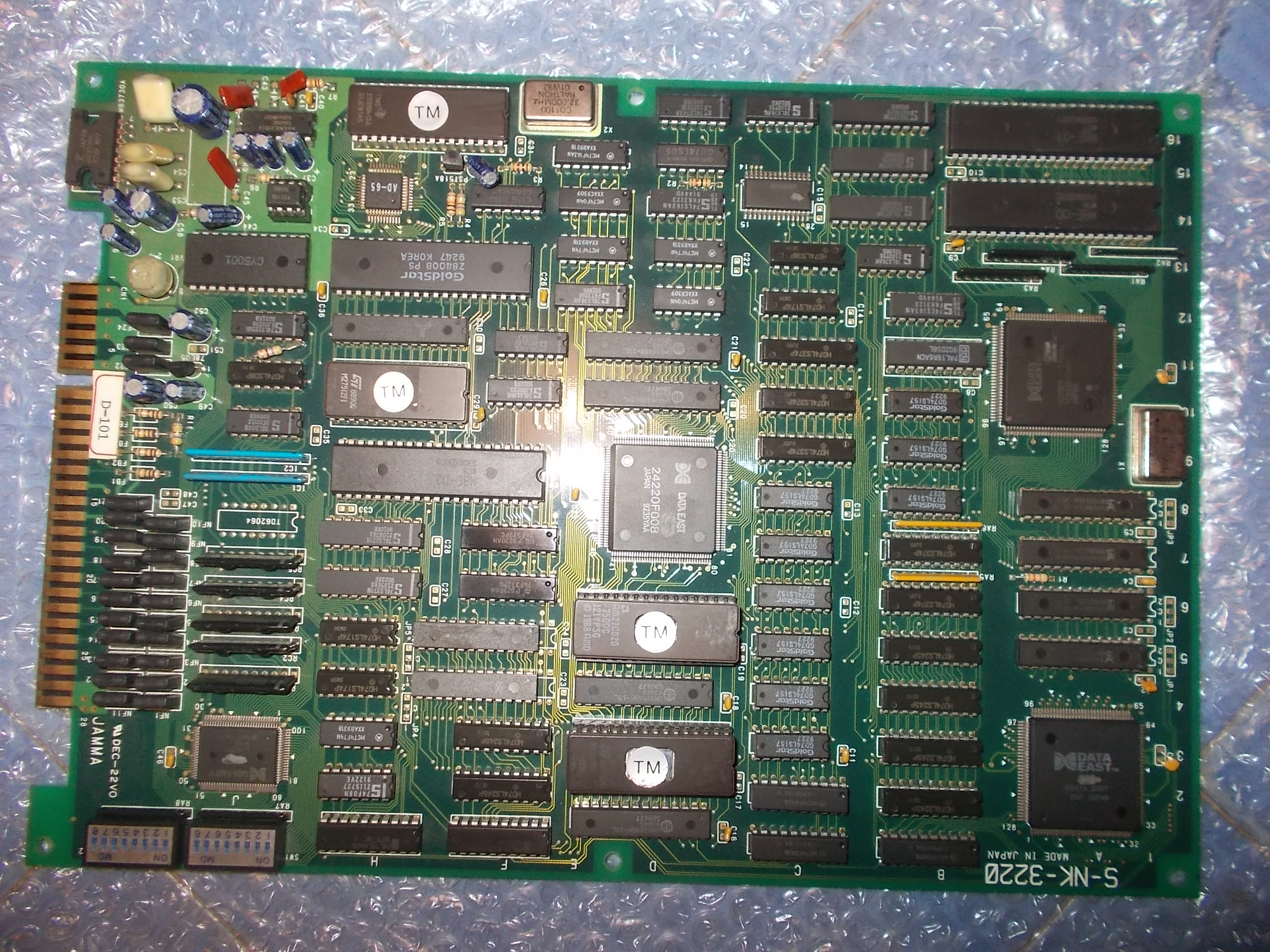
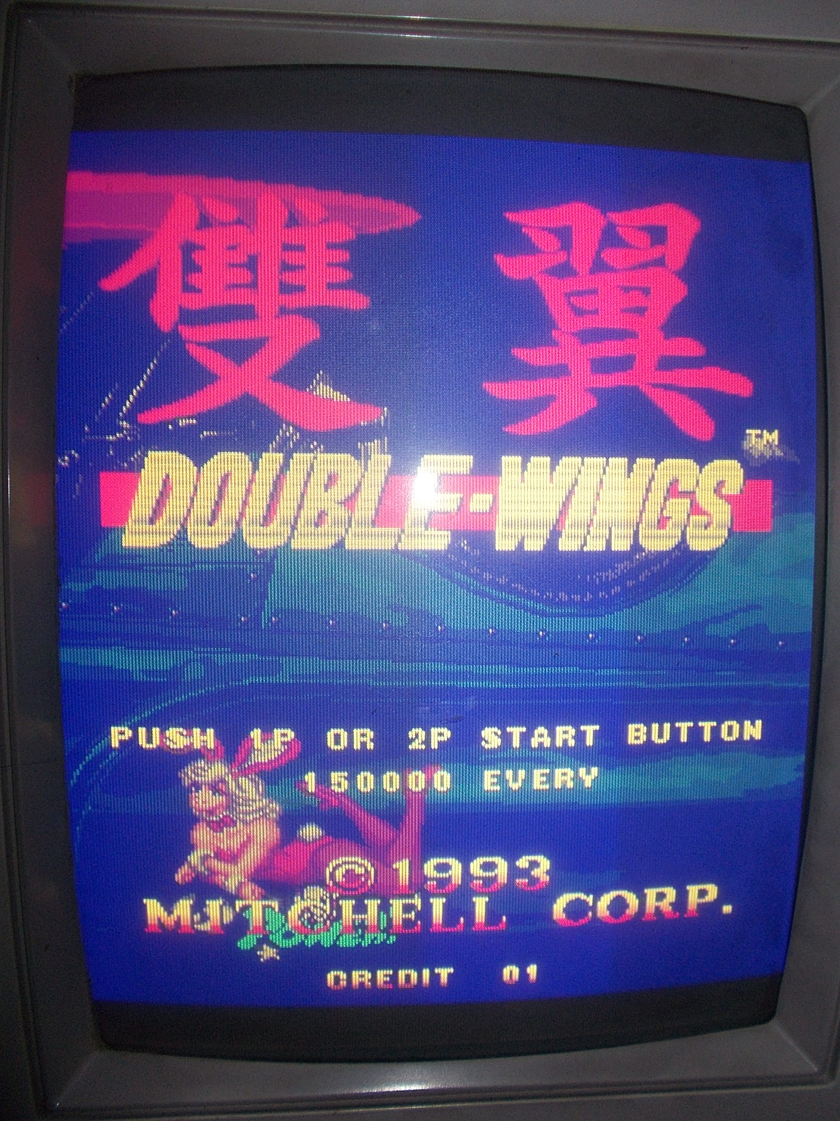
Another shoot’em up on the bench and always a board coming from Portugal : Double-Wings produced by Mitchell Corp. in 1993 (but hardware is clearly marked Data East)

The board booted into game but had a color issue, the screen was all blueish :

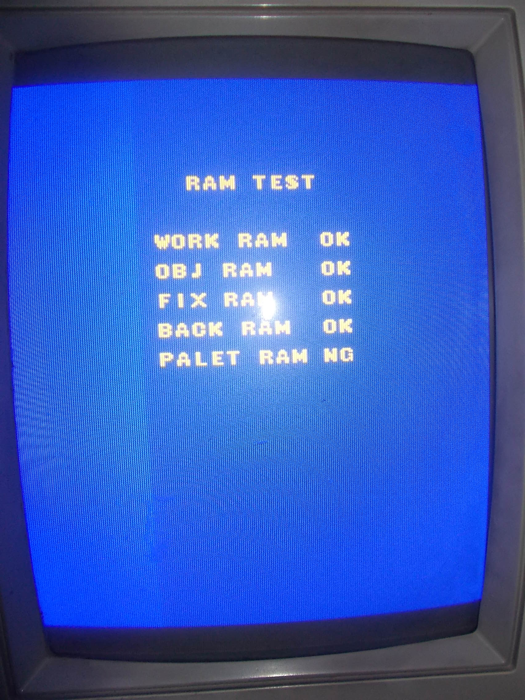
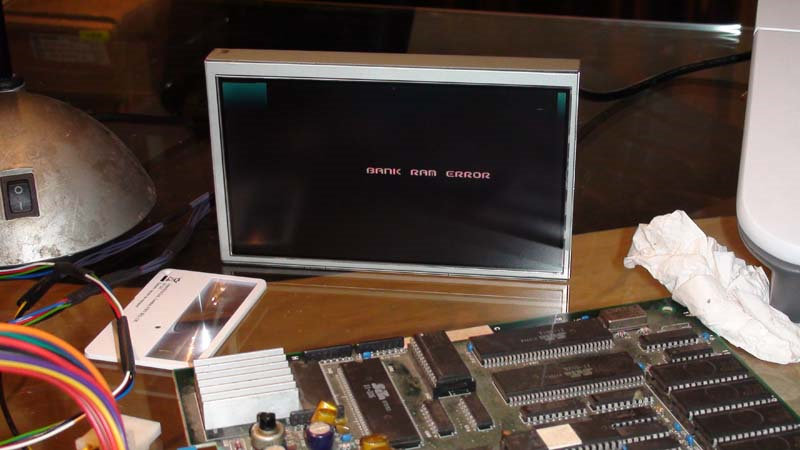
The brief POST showed an error related to palette RAM:

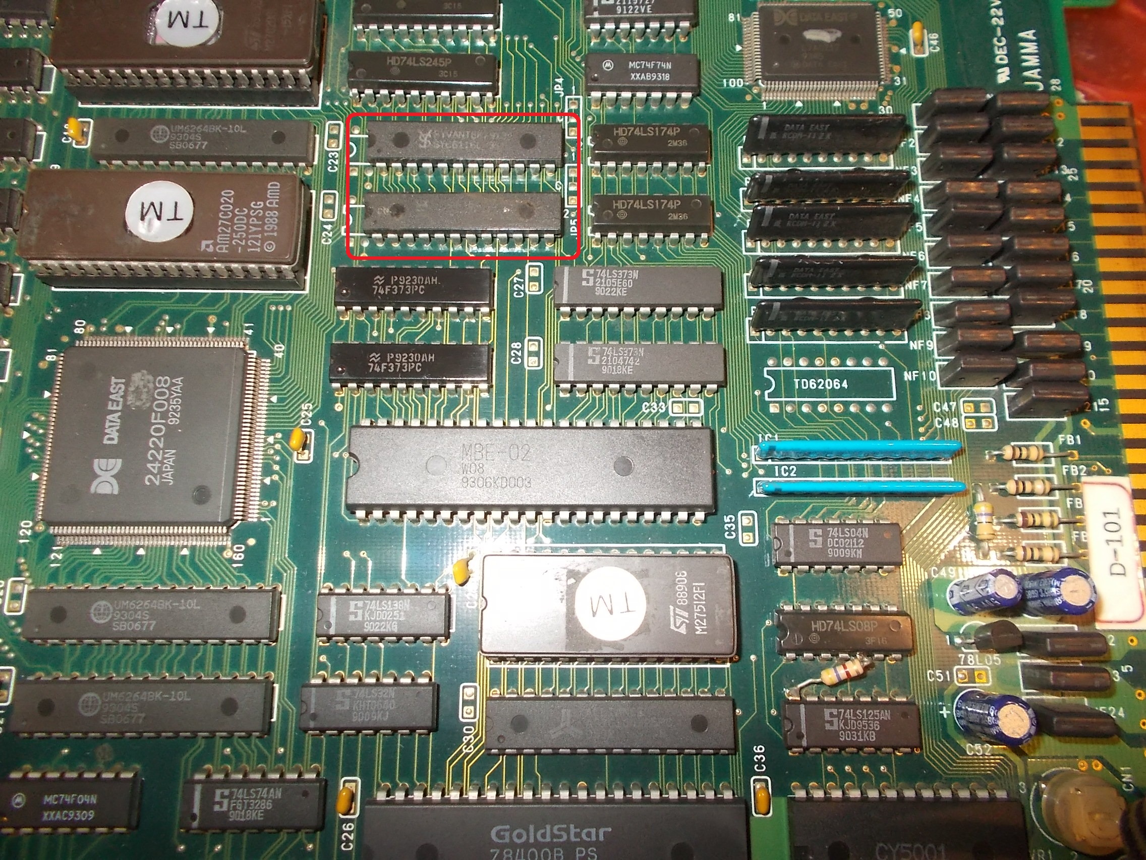
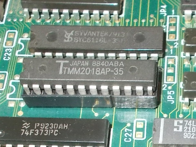
After a quick look at PCB I pinpointed the palette RAMs is two 6116 (2K x 8-bit devices)

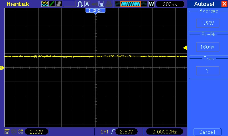
When I went to probe with my scope the lower one @5F I found some stuck data lines:

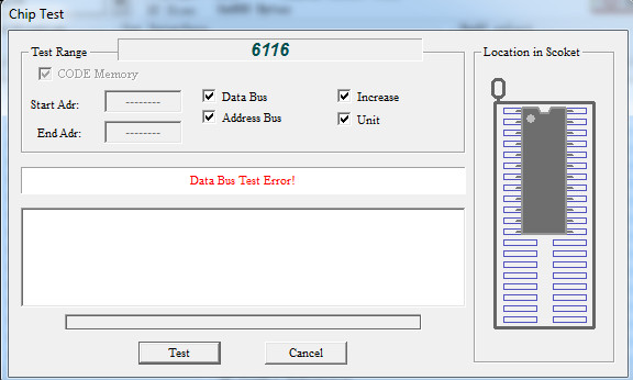
I pulled the chip and tested it out-of-circuit.It failed:

Installed a fresh RAM on a socket :

This fixed the issue and board completely.Another repair accomplished.


 Posted by at 9:37 pm
Oct 022018
 

Got this Explosive Breaker PCB (an unusual shoot’em up from Kaneko) from Portugal for a repair.Board was in good condition but showed some sign of previous rework especially on SMT devices :

On power up the self-test seemed to be successully performed but then an error occured and the board resetted in an endless loop:

Inspecting the board I found that the custom IC marked ‘VU-001’ (involved  in Serial EEPROM and dispwitches handling) was burning hot :

The IC seems to be used on very few other Kaneko PCBs but we looked around and found a donor (Magical Crystals, a maze game) which runs on identical hardware:

I replaced the custom with the spare :

Board finally booted into game but screen was blueish:

A predominance of the blue color means that red channel has troubles or is missing.The RGB colors come from the emitters of three NPN transistors:

Probing the base of the red transistor revealed no signal hence the problem was upstream:

The base is tied to the nearby custom marked ‘699205P’ .

As said before all the SMT devices were previously reworked, also this one showed signs of hot air reflow.Inspecting it with a microscope revealed a solder bridge shorting two pins:

I fired up my soldering iron and removed it, this restored the correct colors and fixed board competely.Job done.

 Posted by at 12:21 pm

Silkworm repair log and Mitsubishi ‘MA7053’ reproduction

 PCB Repair Logs, Reproductions  Comments Off on Silkworm repair log and Mitsubishi ‘MA7053’ reproduction
Sep 282018
 

I had this original Silkworm PCB (manufactured by Tecmo in 1988) in a trade some years ago :

I didn’t know the status of the board since I never looked at it.Quite confident I powered it up but I was immediately disappointed, a solid static blank screen was all I got:

While I was visually inspecting the board I noticed the 28 pin brown SIL hybrid module marked ‘MA7053’ was a bit wonky:

I slightly wiggled it and it fell off:

I installed some 1.778 female pin headers on the PCB:

and patiently soldered the component on a strip of correspondent male headers:

In this way I got the board booting but with severe graphic faults.Color were wrong, sprites flashing (it’s hard to capture this issue with a camera), vertical lines through screen :

I decided to troubleshoot the sprites issue for first.Studying the hardware I figured out that the line buffer is made of twenty 4164 (64K x 1-bit) dynamic RAMs located on VIDEO board  :

Some of them were extremely hot to touch and many showed stuck bit on output:

I pulled them all one by one:

Nine of them failed the out-of-circuit testing:

The graphics were correctly drawn now but the colors still wrong :

Tracing the three colors back from JAMMA connector I figured out the final part of the RGB DAC circuit where I noticed the lack of three resistors @R10-R8-R12 :

I compared my PCB with some pictures online and I had confirm that the three resistors were really missing on my board:

I didn’t know the correct value of these resistors and schematics were not available so I looked at Rygar ones which runs on similar hardware, they were 120 Ohm as part of the R-2R resistor ladder circuits used as RGB DAC:

I installed the resistors :

This fixed board completely:


  • Mitsubishi ‘MA7053’ reproduction

After repaired the PCB I thought this was a good chance to study a replacement of the ‘MA7053’ custom SIL.As often I do in my reproductions I looked at how possibly the custom was re-engineered.I could find two replacement daughterboards.One used on a bootleg PCB :

The other one was from an original Tecmo board (pictures kindly provided by ‘monsterlair’, thanks again to him)

Design were slightly different but they both have same functionality.Technically speaking the ‘M7053’ provides interface between the Z80 main CPU data bus and video memory latching data too.After figured out schematics of the two daughterboards I re-engineered them with surface mounted devices ending up with this result :

Installed on PCB for testing:

Both designs perfectly works on my newly repaired Silkworm :

The ‘MA7053’ is used for sure on these PCBs:

  • Gemini Wing
  • Rygar
  • Silkworm/ Back Fire

But it could be present also on other Tehkan/Tecmo boards so any addition is welcome from all of you arcade collectors/enthusiasts.

 Posted by at 11:15 am