PCB Repair LogsComments Off on The New Zealand Story repair log #4
Nov042018
Received for repair this original The New Zealand Story PCB (one layer hardware revision)
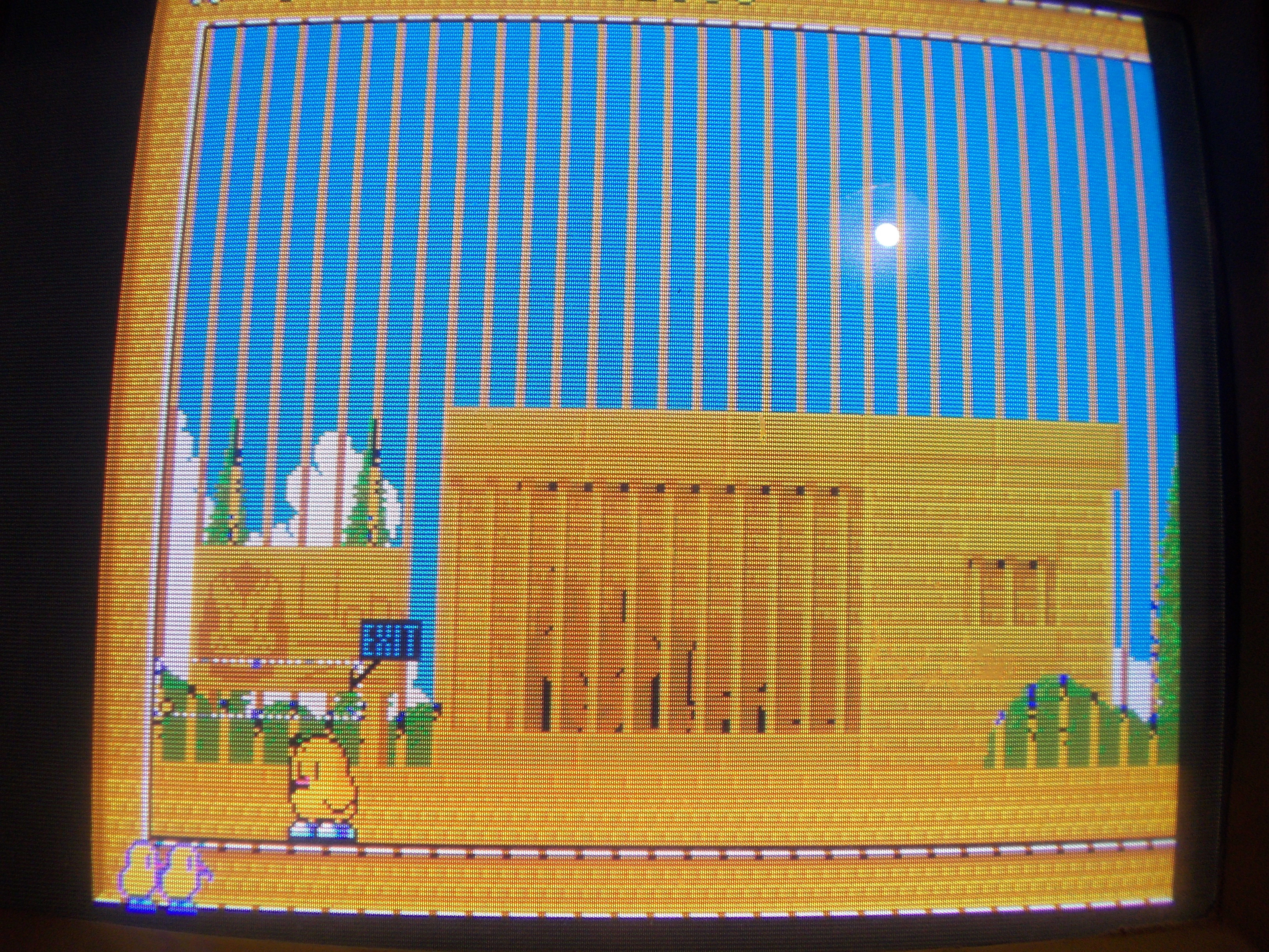
Board played fine except for this issue concerning background graphics, they had jail bars though :
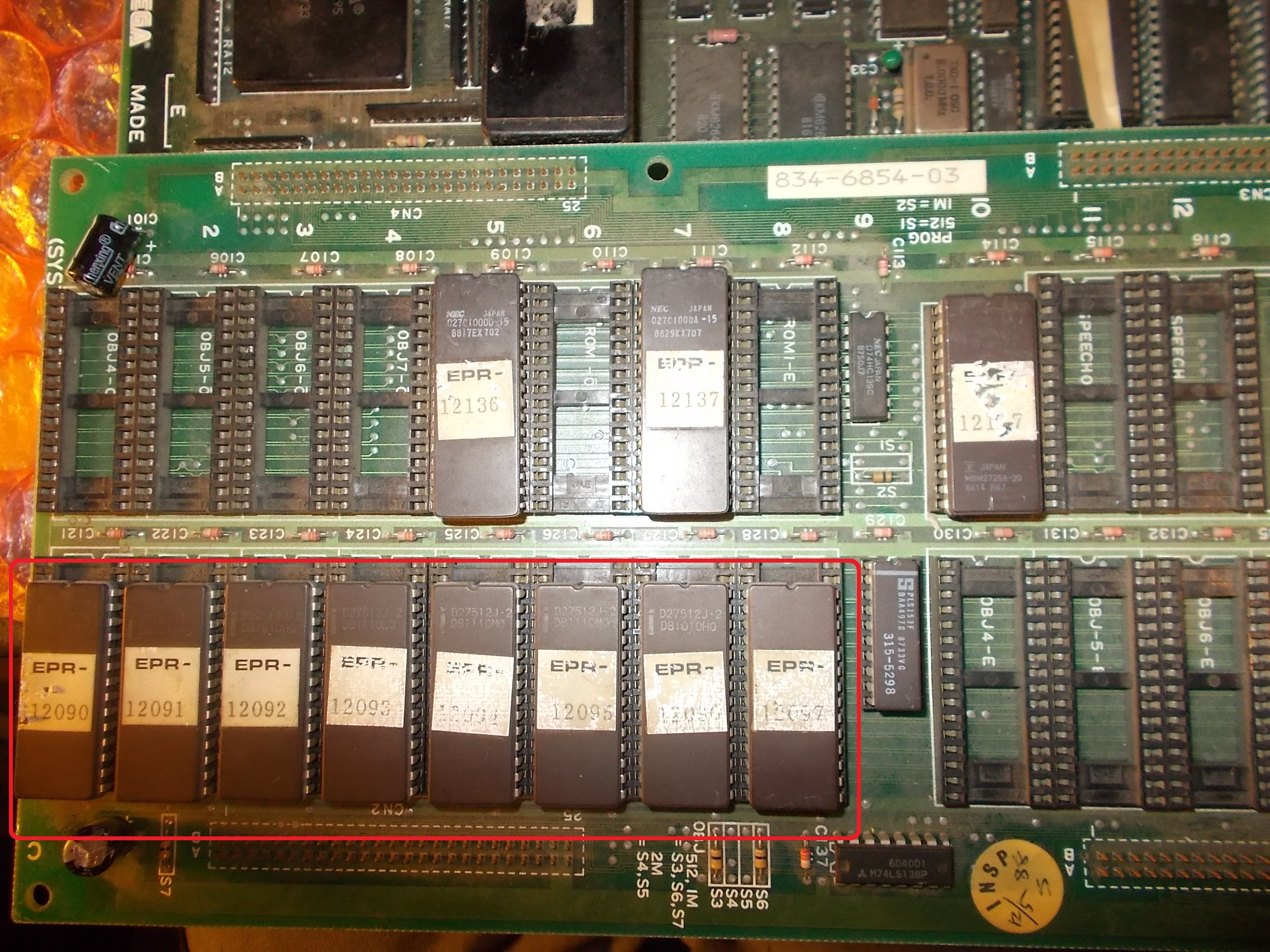
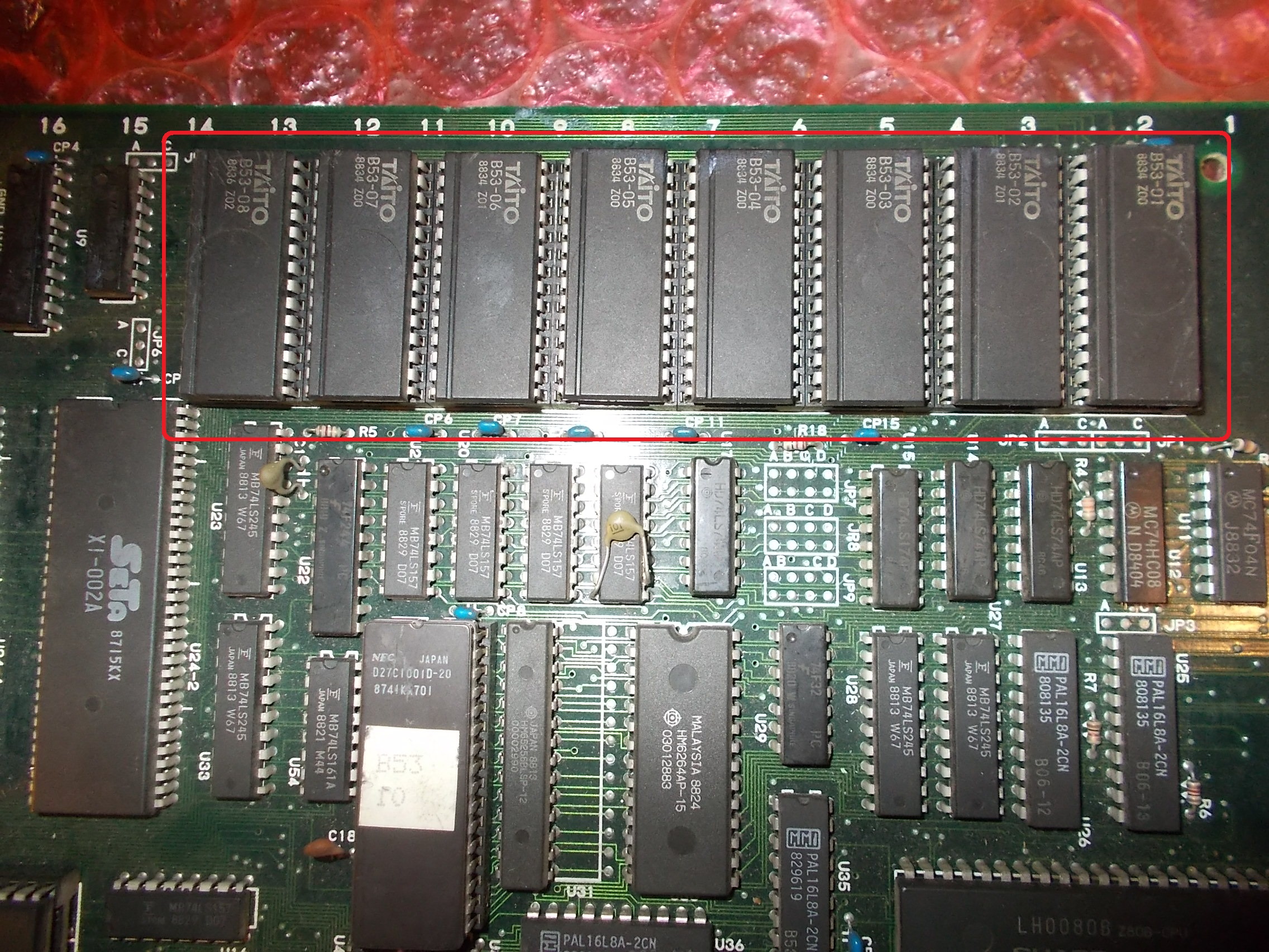
All GFX data are stored in eight 1Mbit 28 pin MASK ROMs :
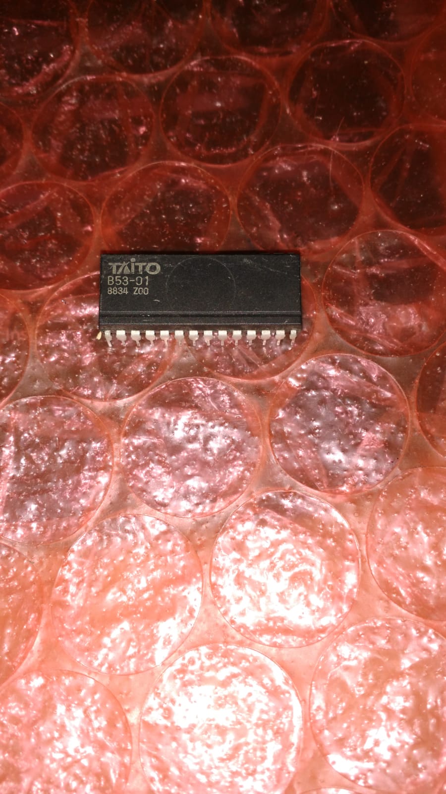
I dumped them starting from the one on the right labeled ‘B53-01’ :
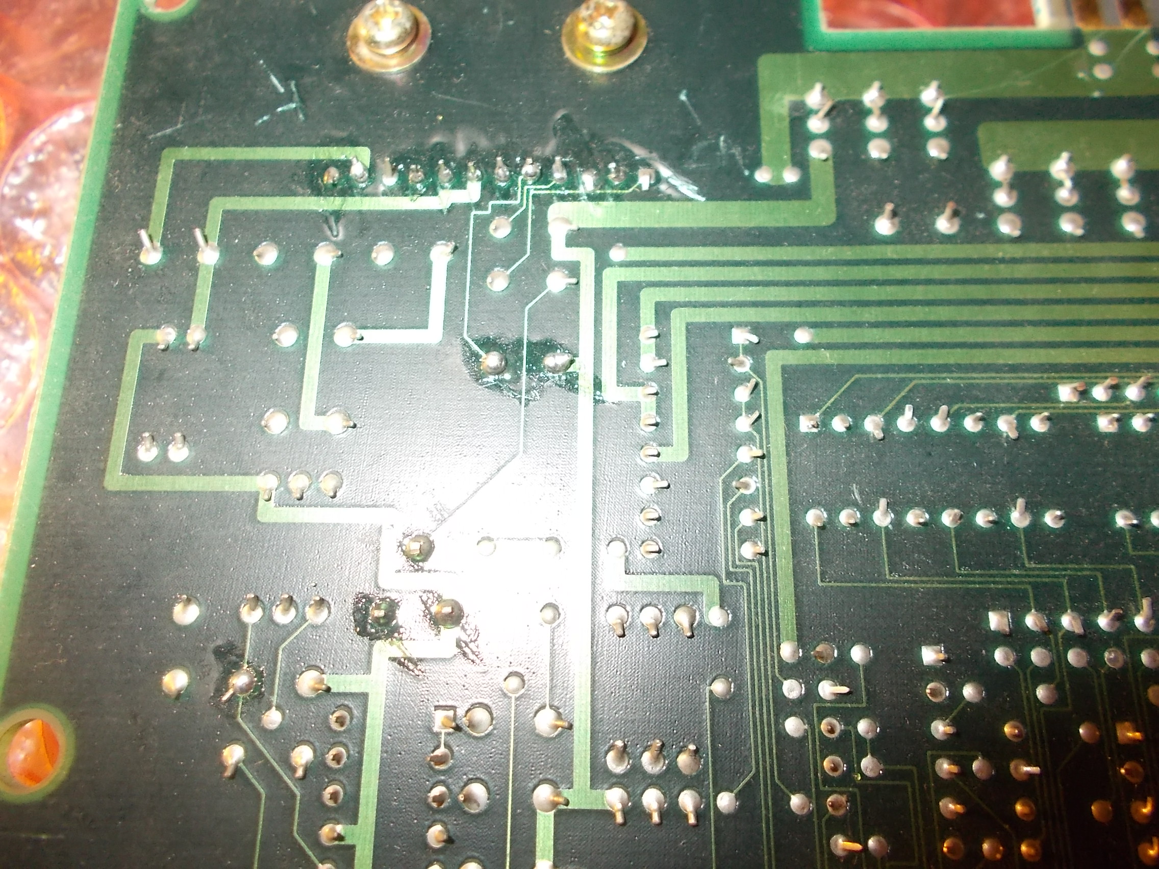
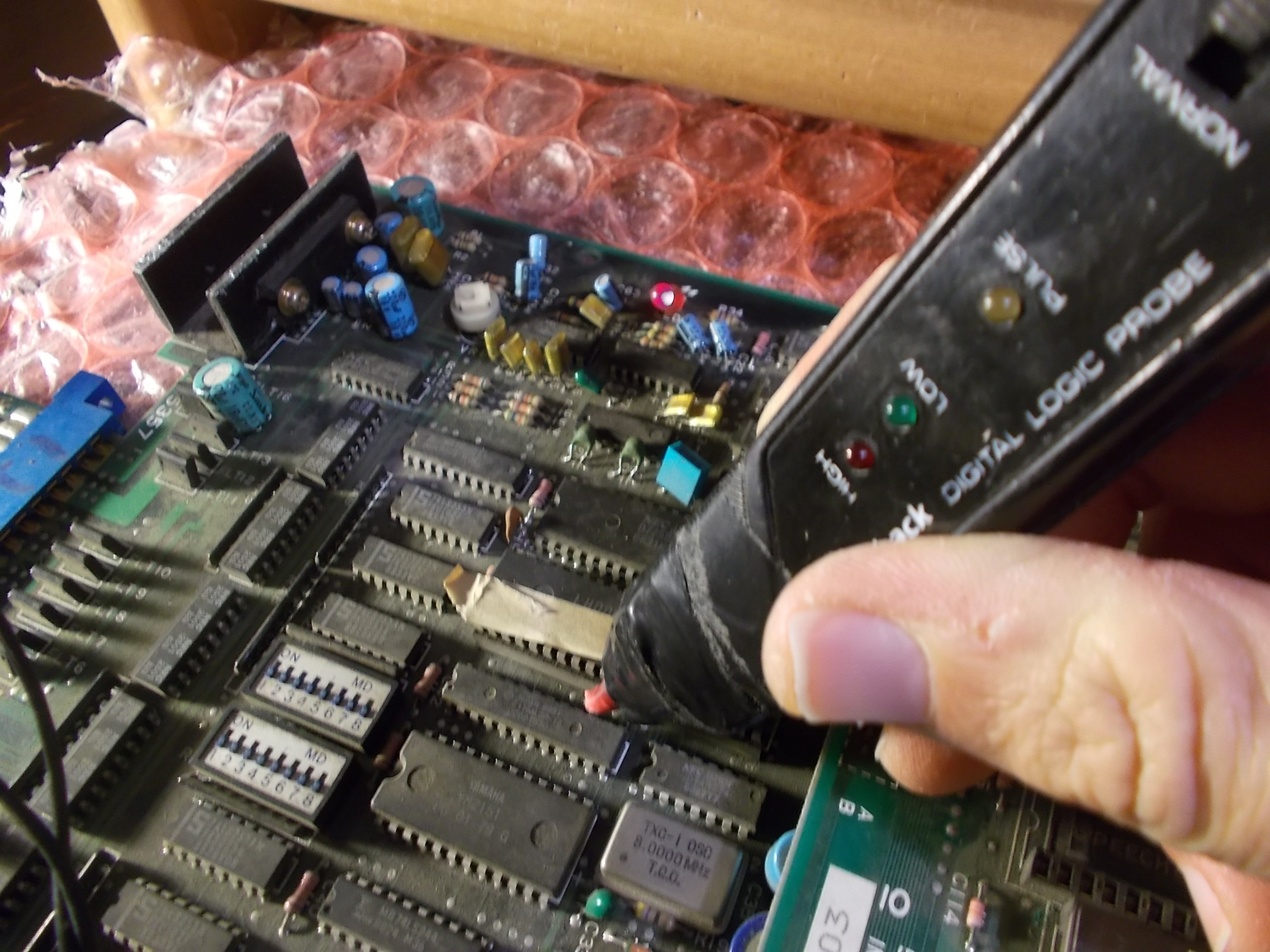
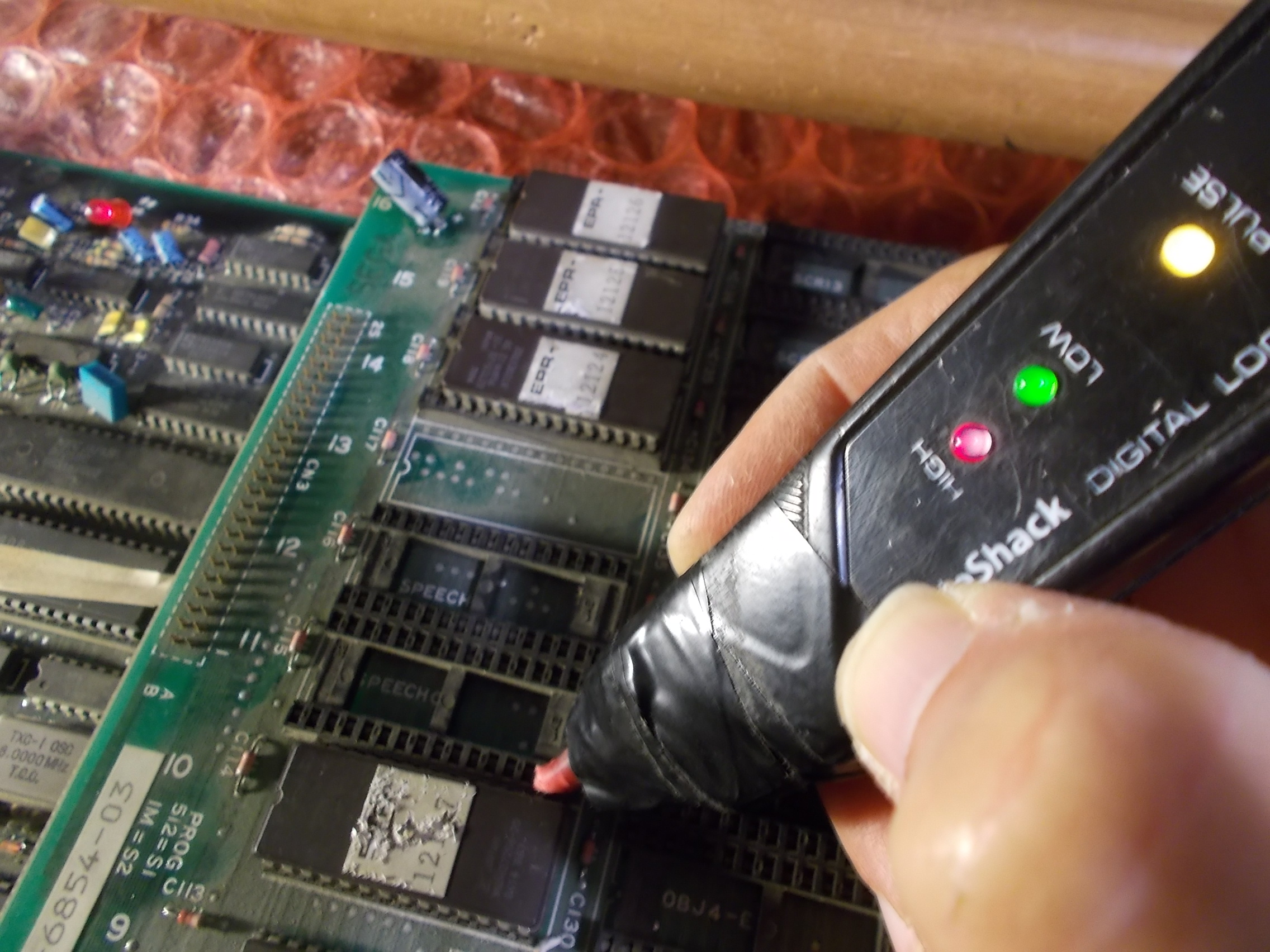
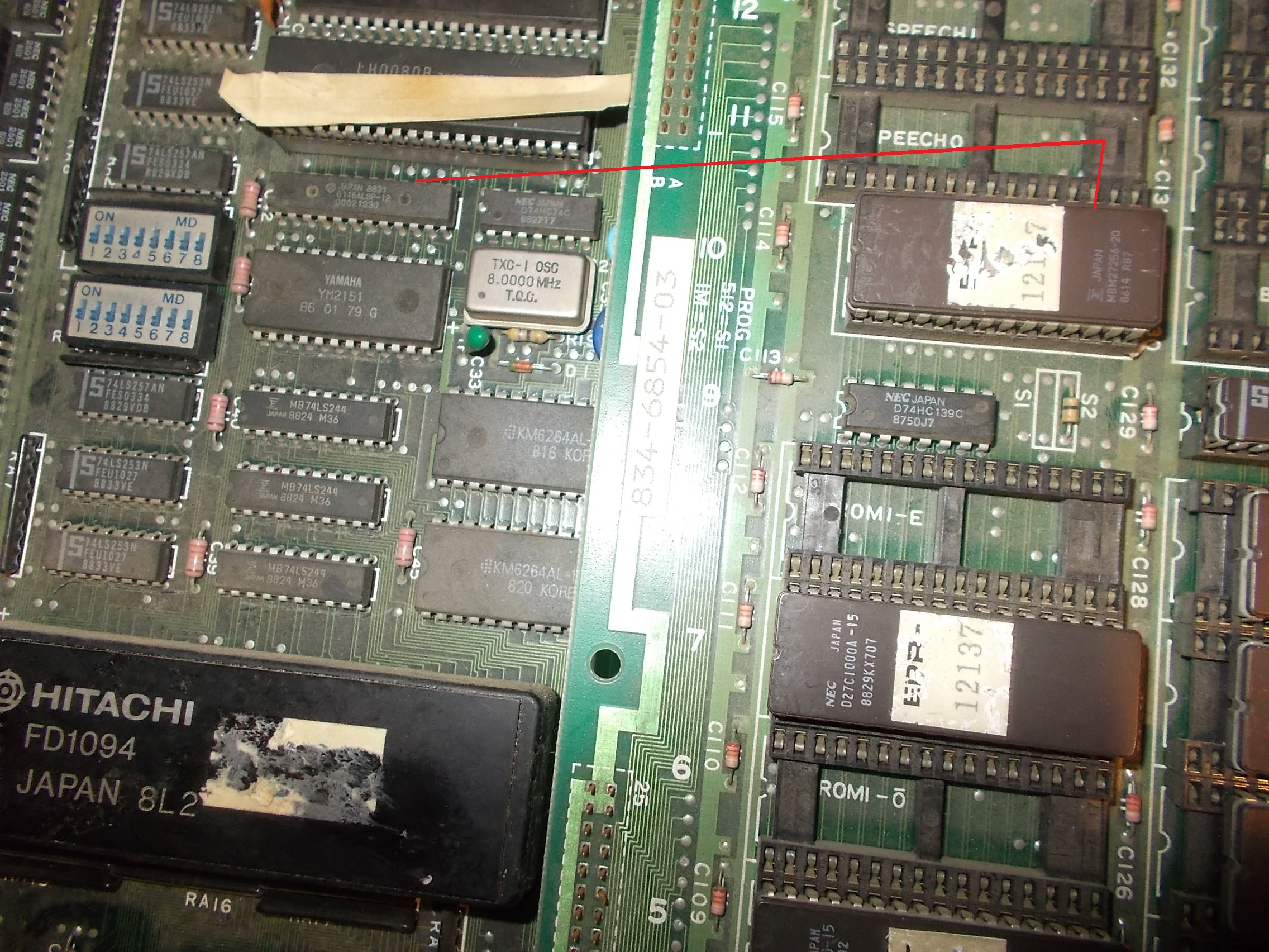
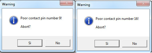
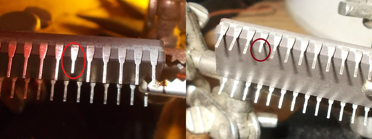
And my programmer complained about a bad contact of pins 18-19 (which are data lines)
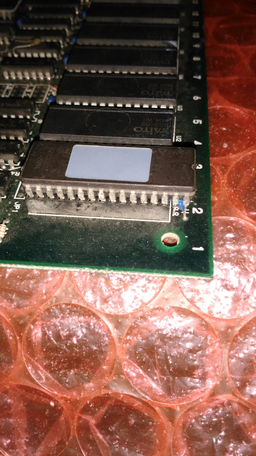
As said the device is a 1Mbit 28 pin MASK ROM which no direct replacement exist of, the only option is to adapt a 1Mbit 32 pin EPROM (better with non-JEDEC pinout), that’s what a made :
Perhaps not the best looking solution but it fixed board completely.Job done.
P.S.
This repair inspired me so I made my own design to adapt a 1Mbit 32 pin TSOP Flash ROM to the 28 pin 1Mbit MASK ROM pinout:
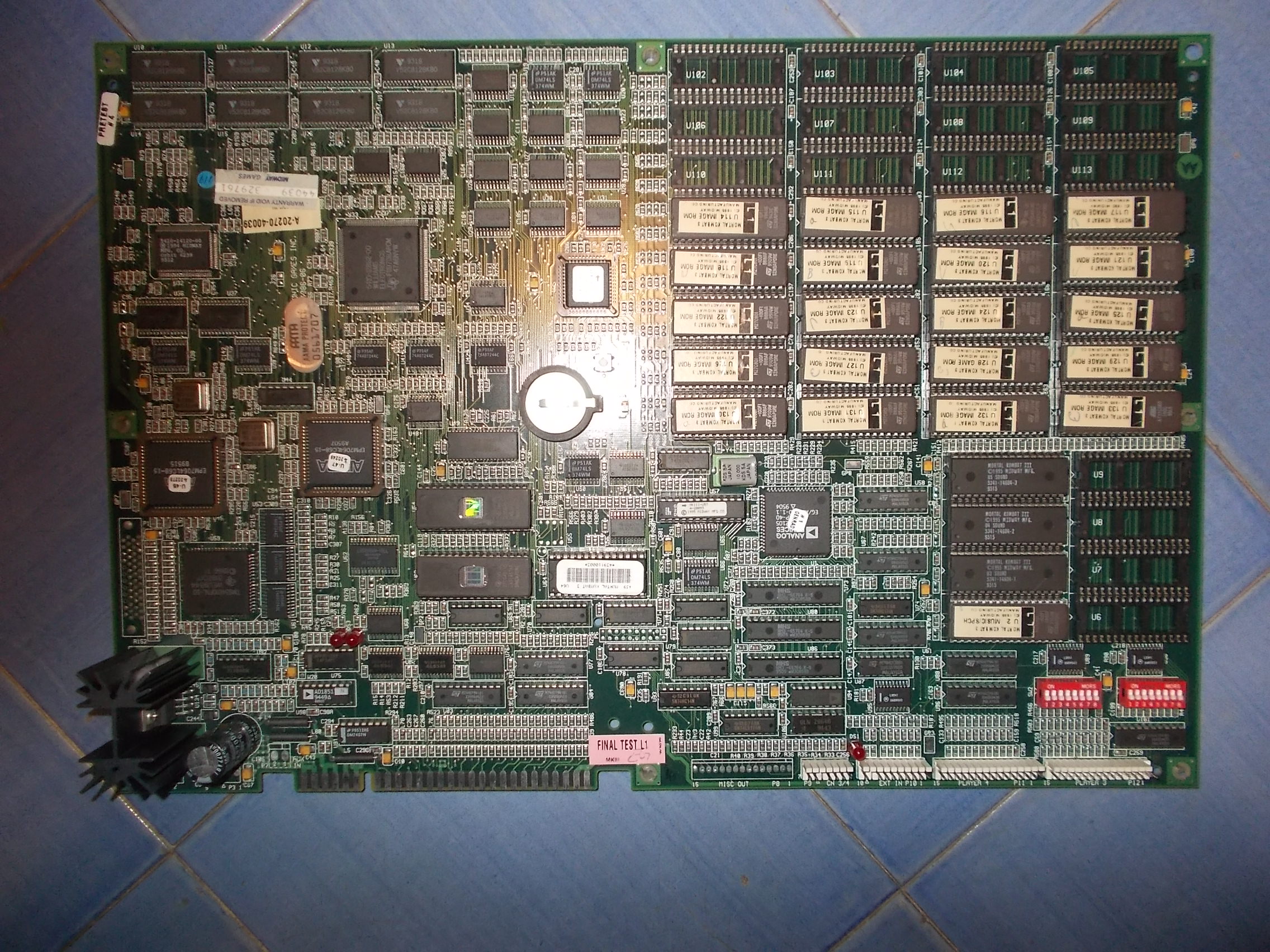
Received this original Mortal Kombat 3 PCB (manufactured by Midway) for repair: The Power-On Self-Test reported three bad RAM devices @U14-U36-U37 :
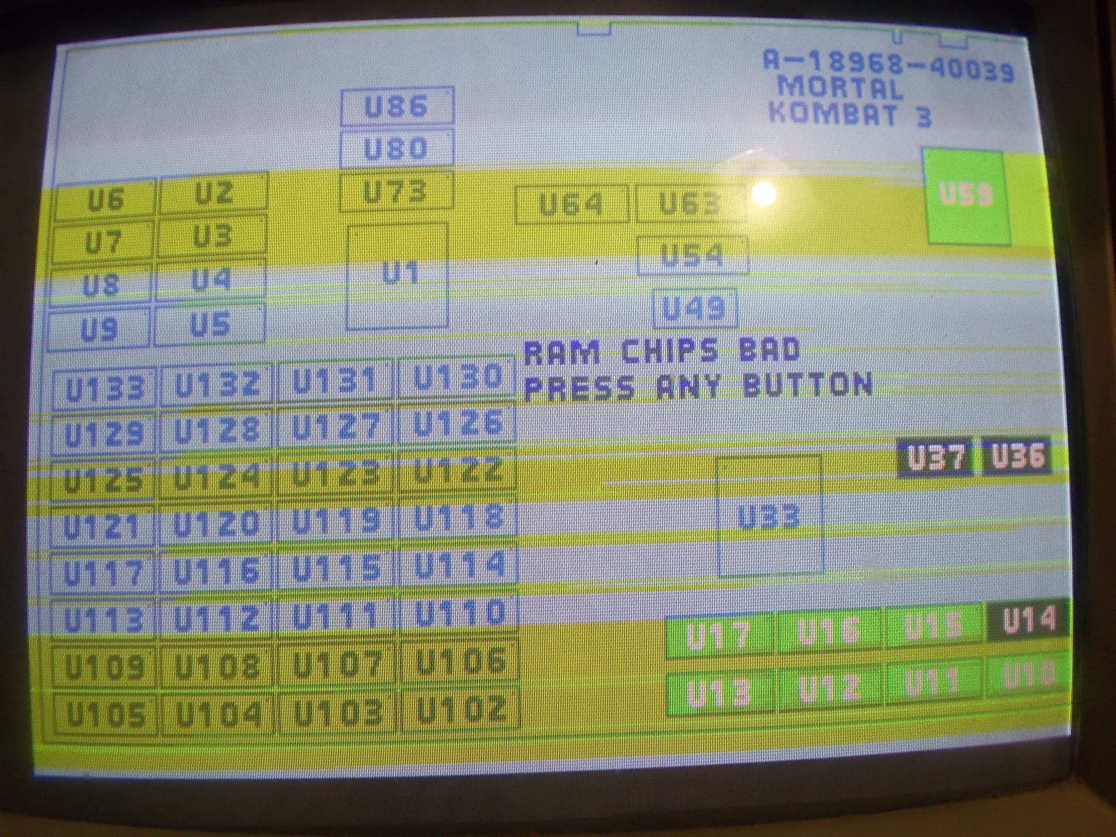
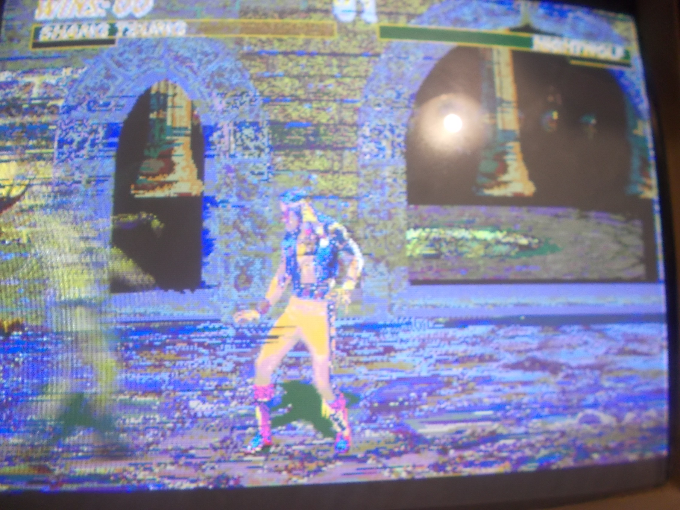
Board then went into game with bad graphics and colors:
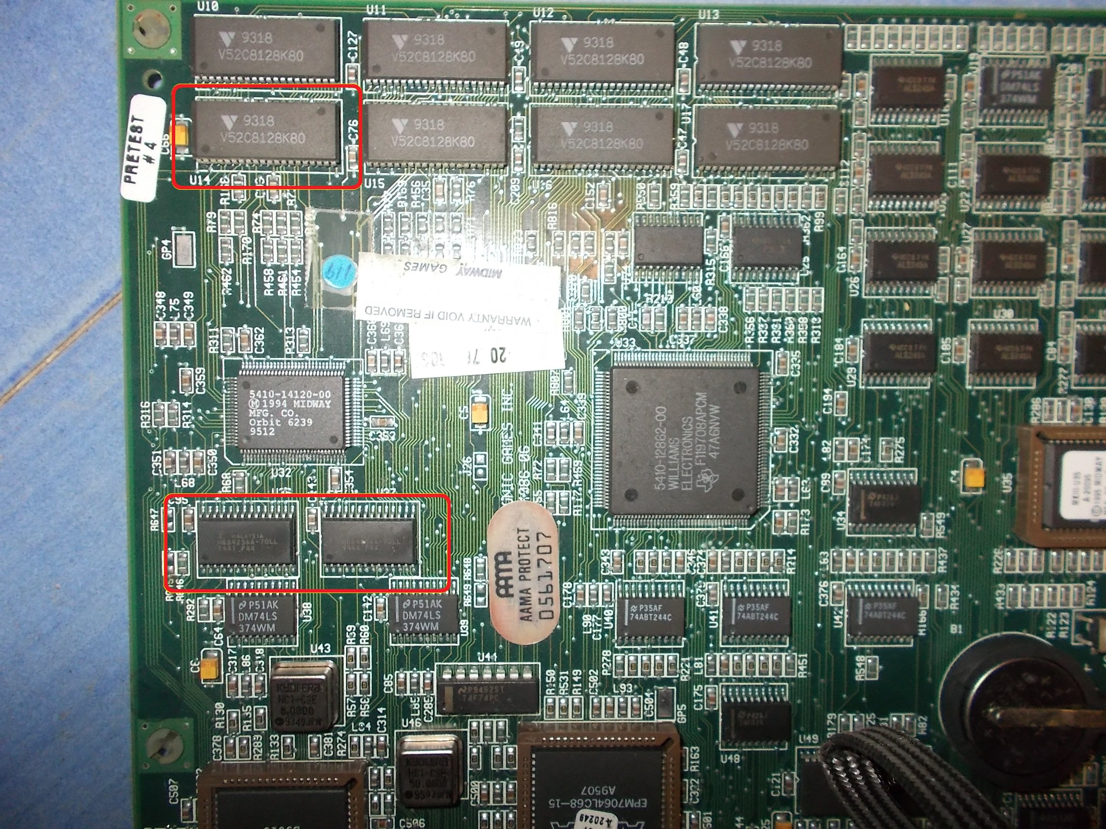
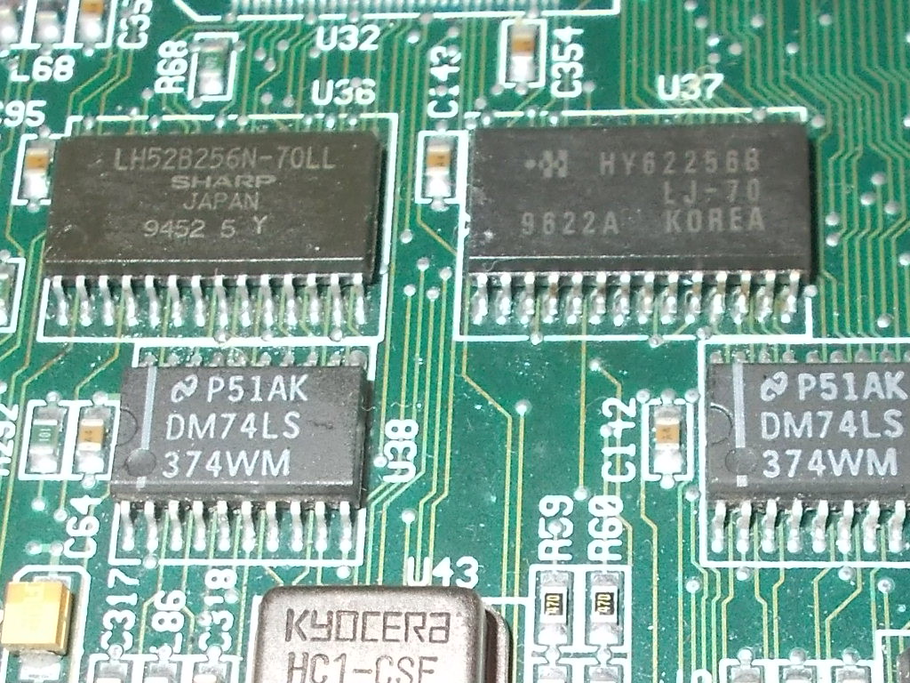
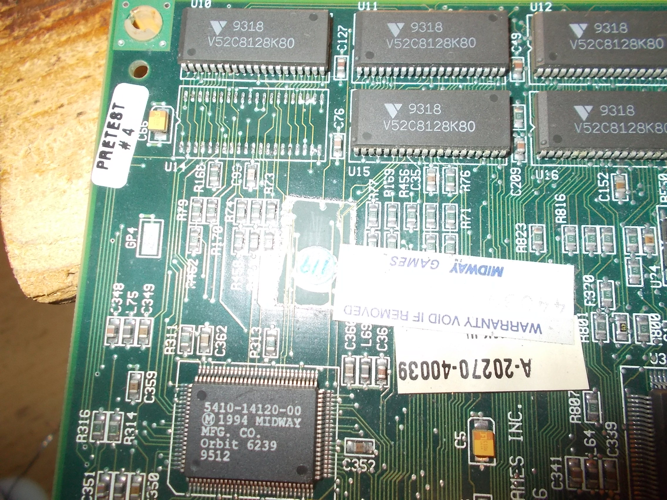
The three RAM given as bad are two Fujitsu MB84256 (32K 8-bit) palette SRAM @U36-U37 and one Vitelic V52C8128 @U14 :
As for the two palette RAMs I had no problem in finding spares and replaced them with two equivalent with same access time of 70ns:
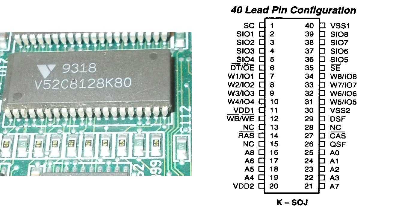
The one @U14 was tricky since it’s a multiport VIDEO RAM with 128K x 8 DRAM and 256K x 8 SAM (in SOJ package) rarely used on arcade hardware :
I could find three possible equivalents:
Toshiba TC528128B
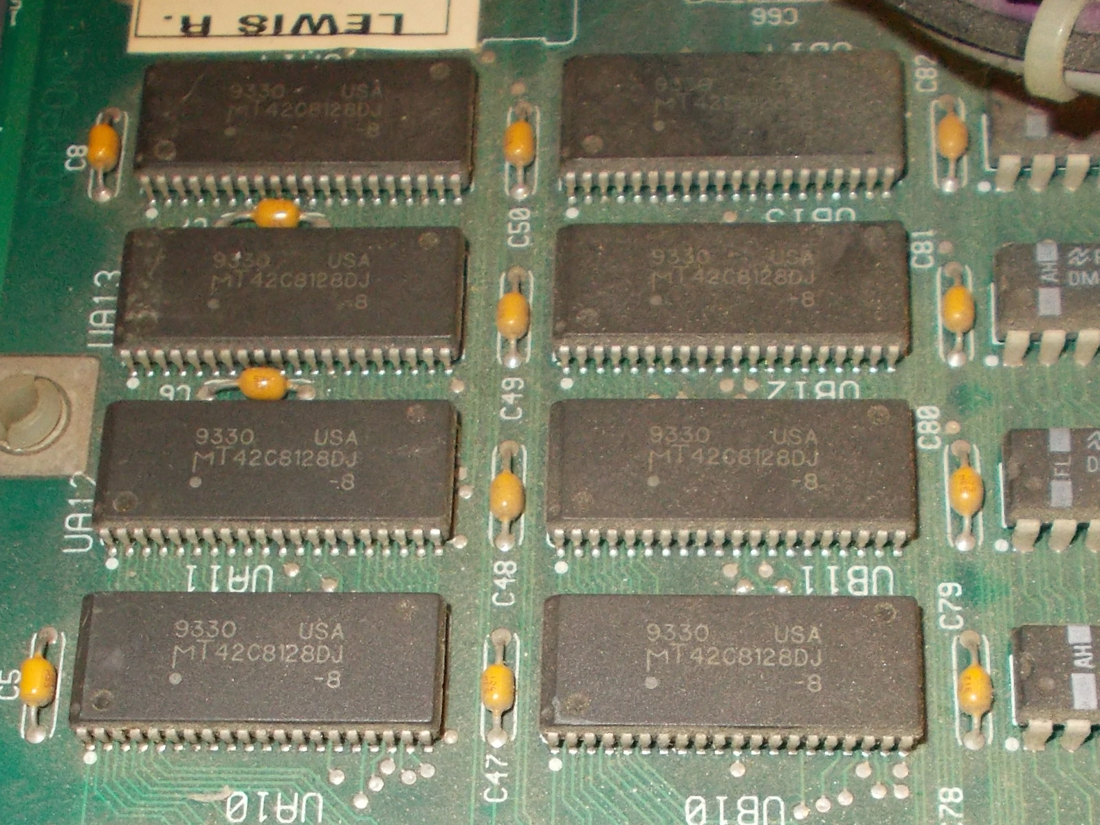
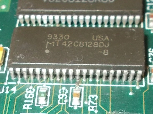
Micron MT42C8128D
Hitachi HM538123
I was about the order the part online when I remember I had a dead NBA Jam PCB (which runs on similar hardware) somewhere.I digged it out and found it luckily used these RAMs :
But then I remembered I repaired another same PCB which had only one EPROM for audio samples whereas the other socket was empty.Other pictures found on the net confirmed this too like this one taken from ‘system11’ blog:
So I removed the one @1F and sound was fully restored.
Now the sprite issue.Hardware used the custom ASIC (in QFP160 package) marked ‘MXC 06’ which generate objects :
We can see its pinout in the Oscar schematics:
Since the ROM board covers entirely the ‘MXC 06’ custom ASIC denying me any access to probe its pins I decided to replace it given also the fact there is almost nothing else involved in sprite generation :
I took the spare from a dead Sly Spy/Secret Agent PCB and soldered it pin by pin with the iron tip:
When I powered the board up again, the glitches on sprites were gone so I could declare the board as 100% working.End of job.
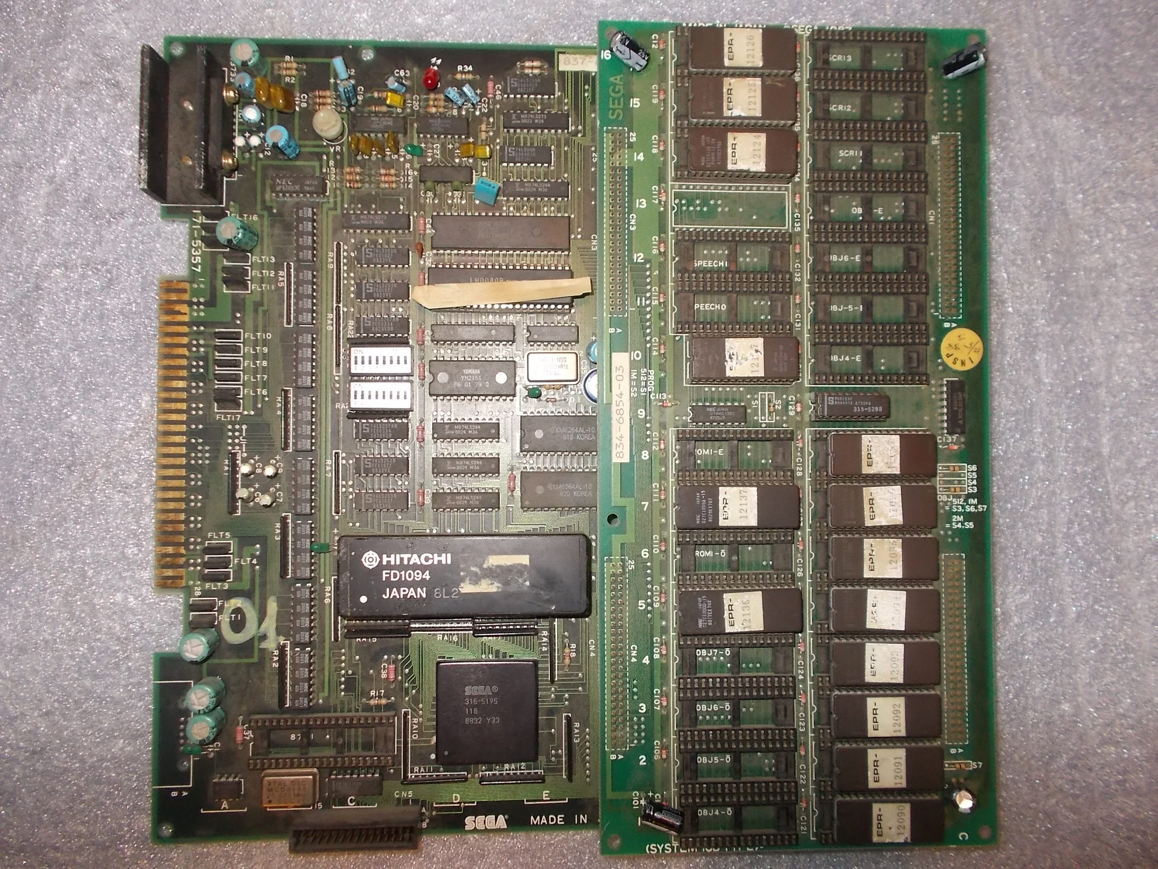
This PCB from my collection had a subtle problem after some minutes of being turned on and with voltages more than 5.1V
Some lines of the sprites started to be shifted toward the left
If I lowered the voltage to exactly 5V the sprites were good.
Being a perfectionist I started to find the culprint and eventually I found the circuit involved in the problem.
If I put the oscilloscope tip on pin 2 of 74LS365@IC55, the problem got worse, more lines were shifted to the left.
The chip was good so I changed also all the components which were in the chain, a 74LS245@IC56 and a couple of rams @IC57 and IC58
It must be said that all these components had healthy a good looking signals on the oscilloscope and they were tested good out of circuit but I decided nevertheless to change them with other brands to rule out every possibility
Still same issues after some minutes powered on
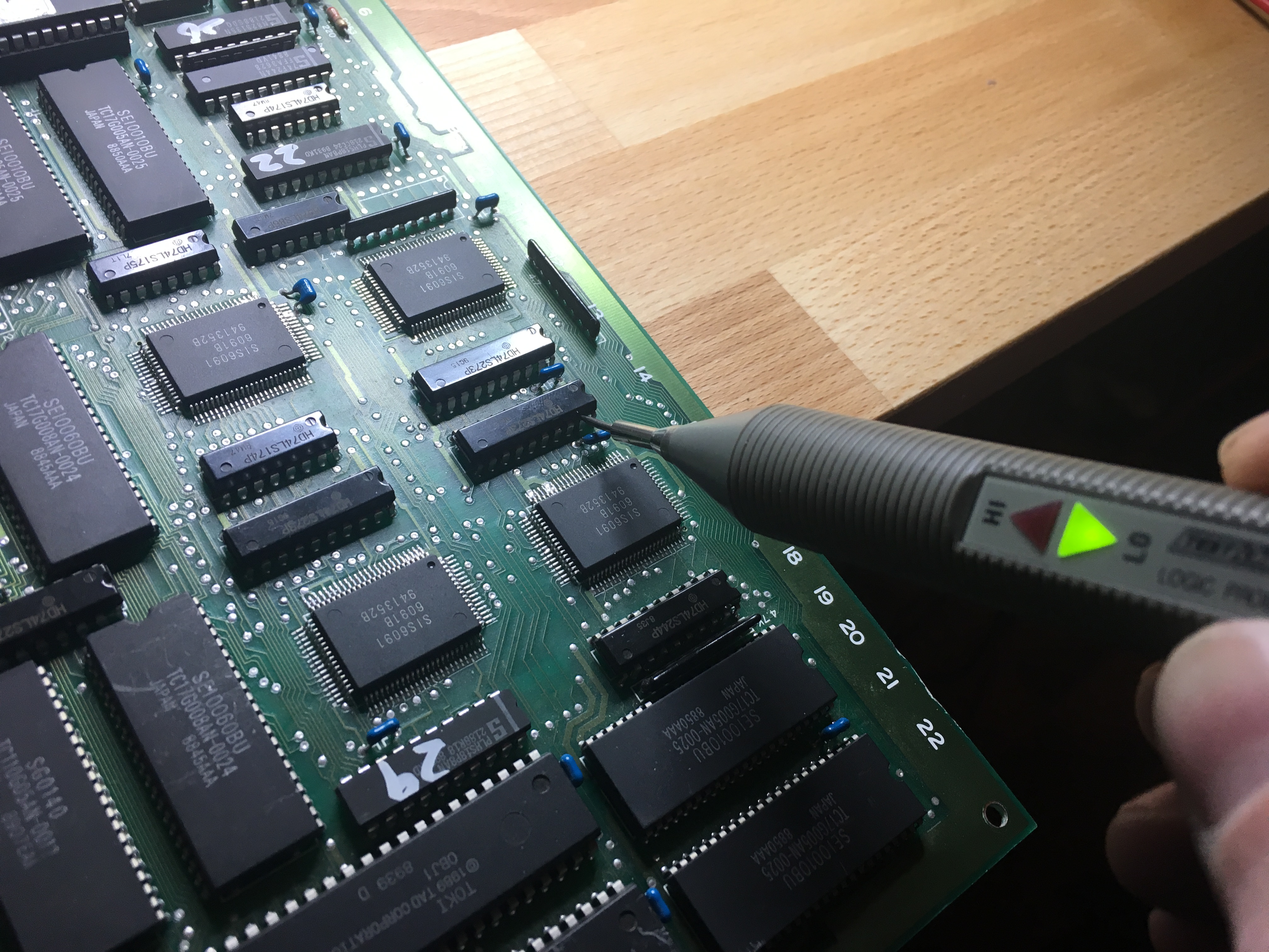
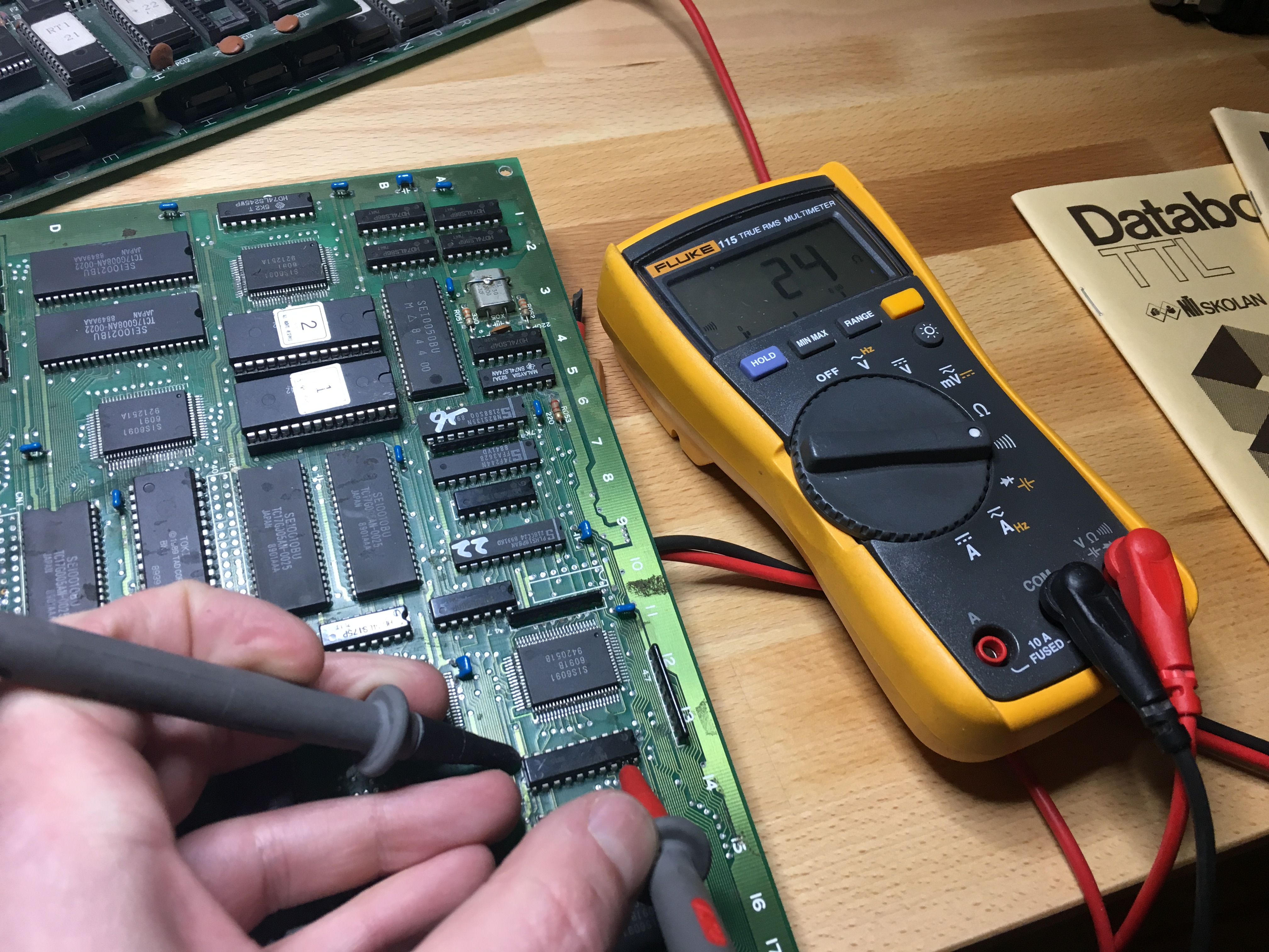
At this time I really thought it was either the sprite maskrom or the custom chip which was the source signal of pin 2 of 74ls365 until I noticed that the same signal was also connected to pin8 74LS273@IC94 which was pretty far from the other chips in the chain.
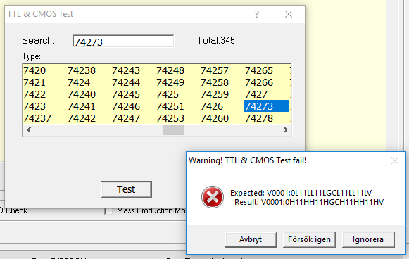
I decided to make a piggyback with a good chip and the problem desappeared completely at all voltages.
I changed it without further checking and still the problem was there!
With the tip of the oscilloscope I touched pin 8 and the problem disappeared immediately.
The oscilloscope probe has some capacitance which delayed somewhat the signal and fixed the problem.
So I installed a ceramic cap between GND and pin 8 and the problem was 100%
I think that this board had always a timing issue that no one addressed and preferred to run it with exactly 5V