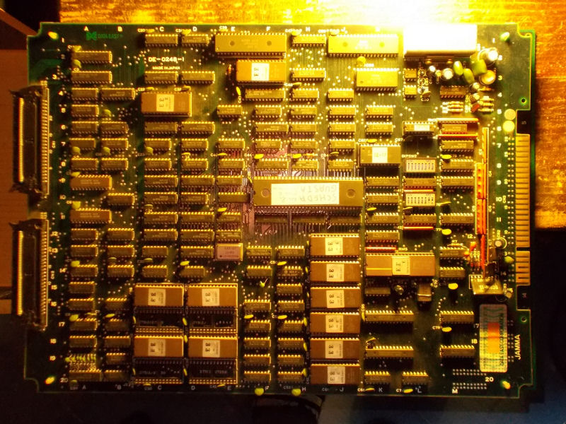
Another double Tube Panic PCB repair, with this so far fourth are the PCBs I repaired for my friend ‘robotype’ (you can find here the first log).Let’s start with first one :
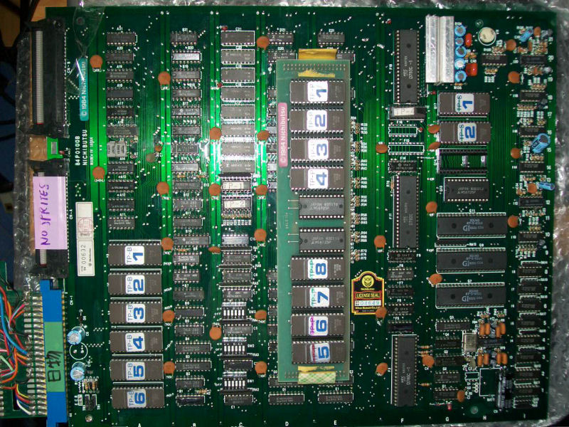
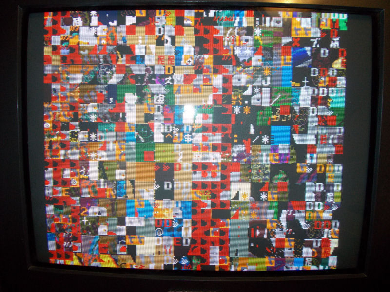
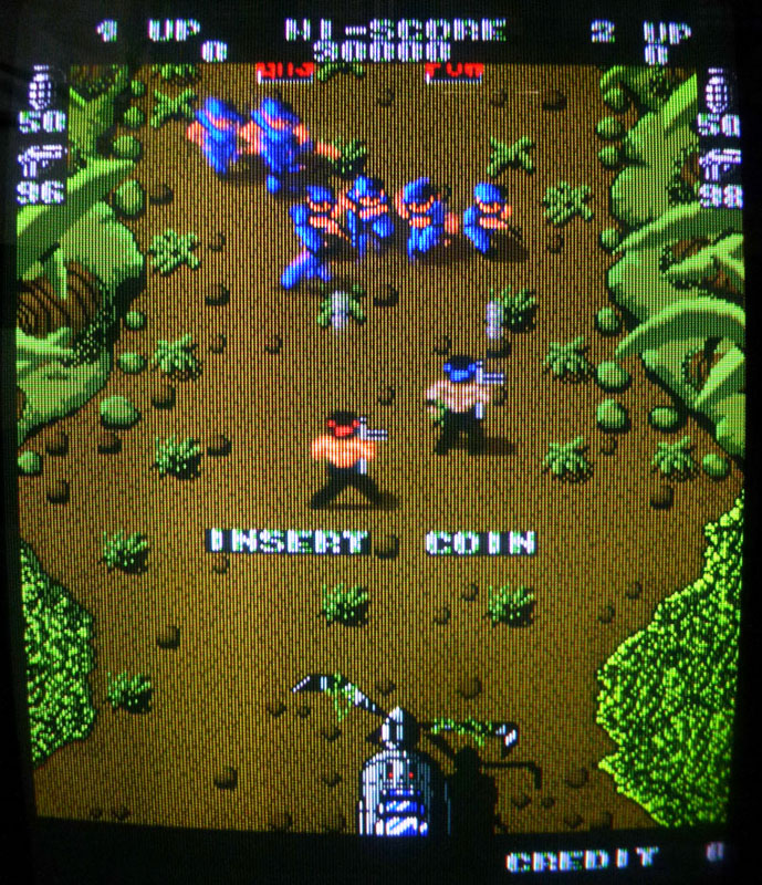
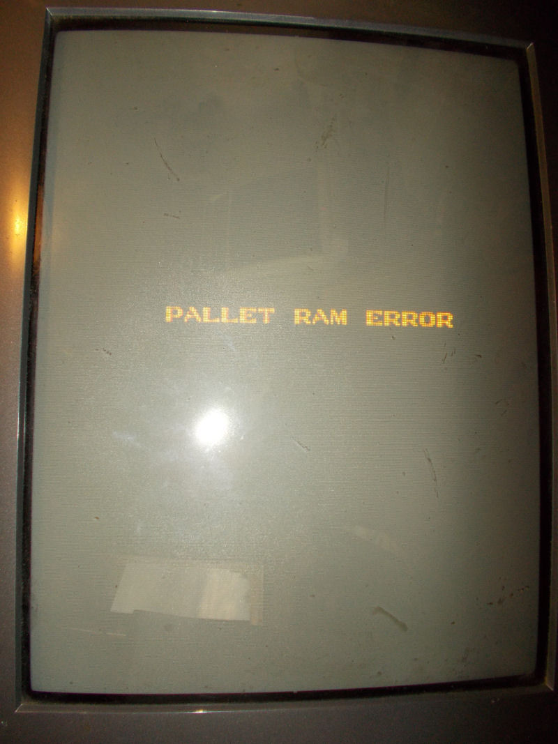
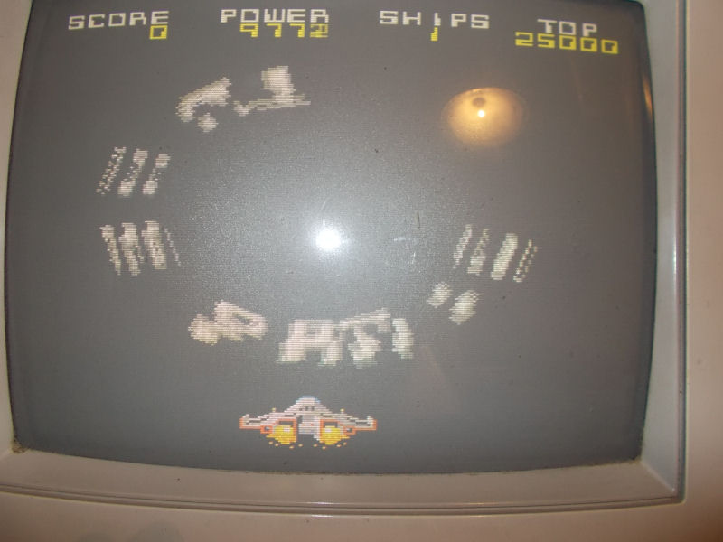
As label said, sprites were totally missing:
![]()
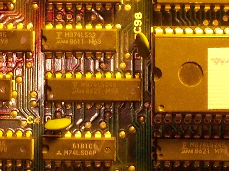
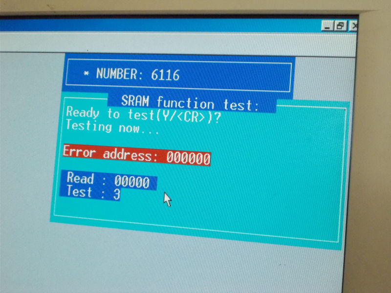
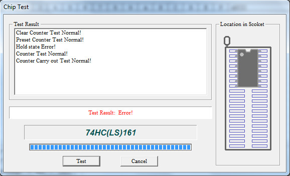
Sprites generation circuitry is located on the video board.ROMs were all good so, due lacks of schematics, I went to test components with my HP10529A logic comparator.When I clipped a 74LS161 counter @E8, comparator reported troubles on all its output pins:
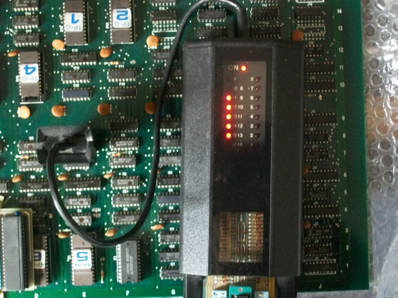
It failed the out-of-circuit test:
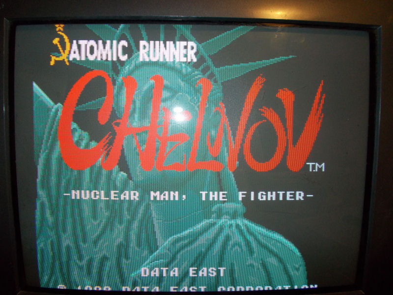
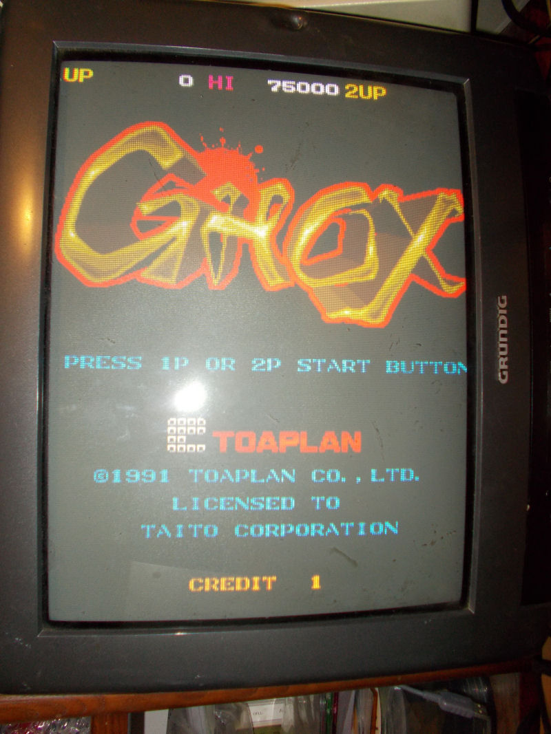
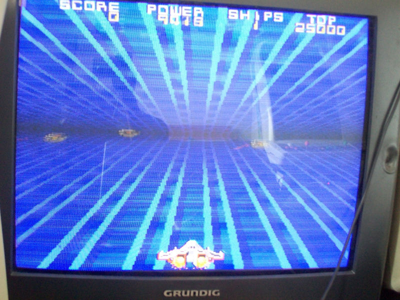
With a good IC fitted, sprites came back :
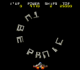
First board 100% fixed, let’s pass to the second one which was labeled with “BAD SPRITES” (it seems sprite issue is a common failure on all the Tube Panic PCBs) :
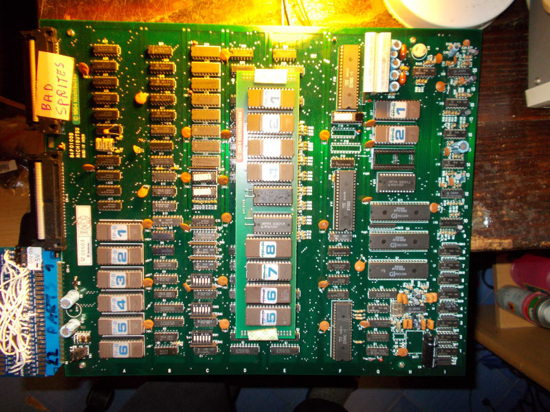
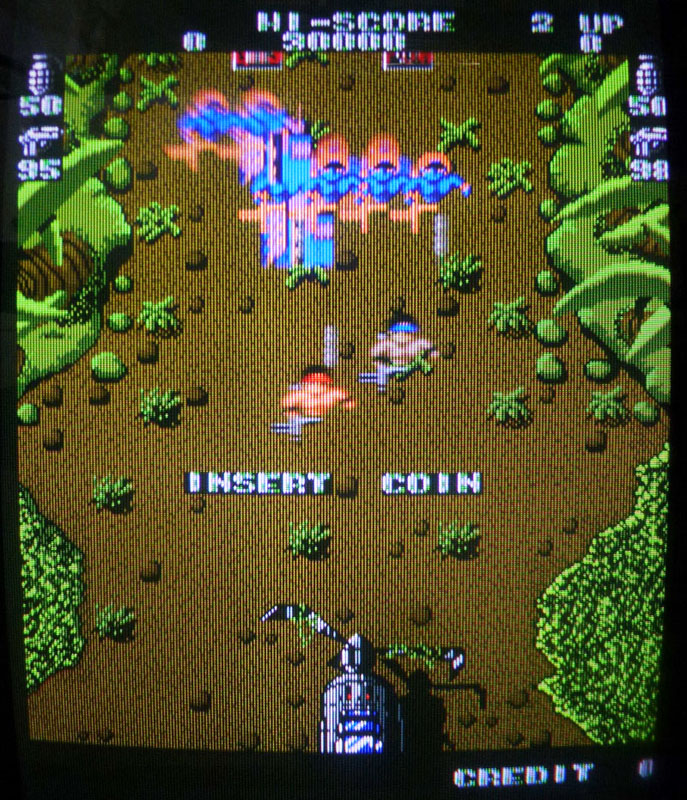
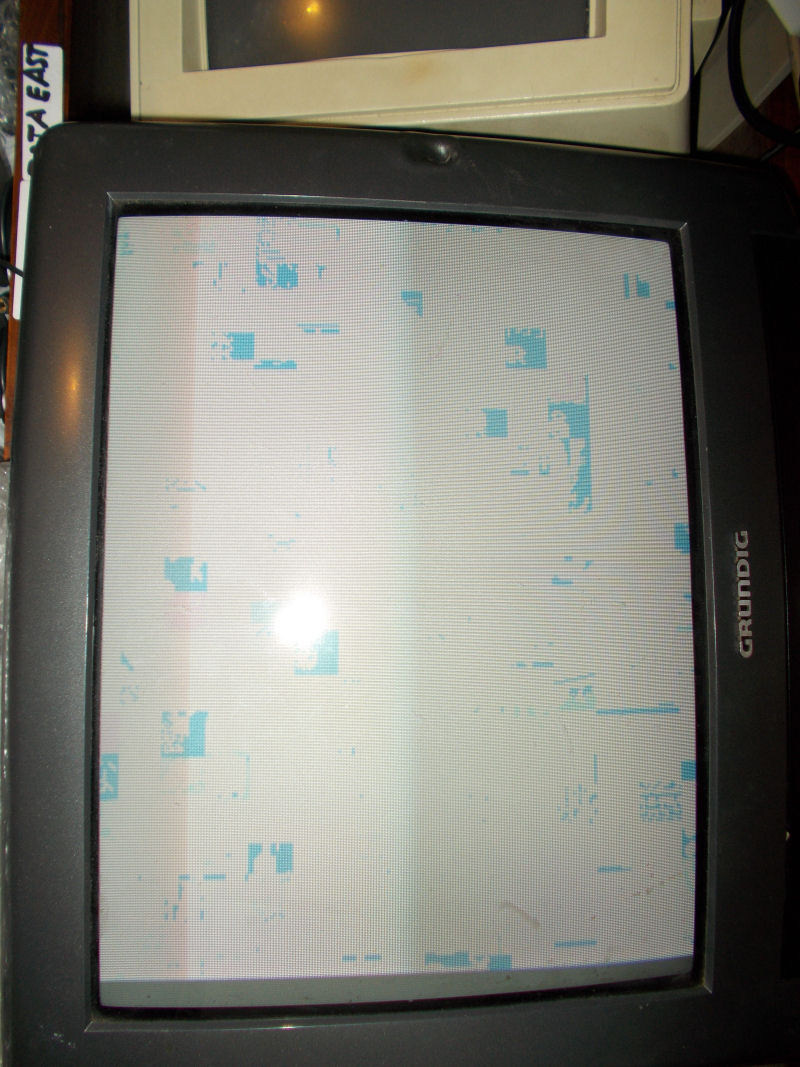
This was confirmed once powered the board up:
![]()
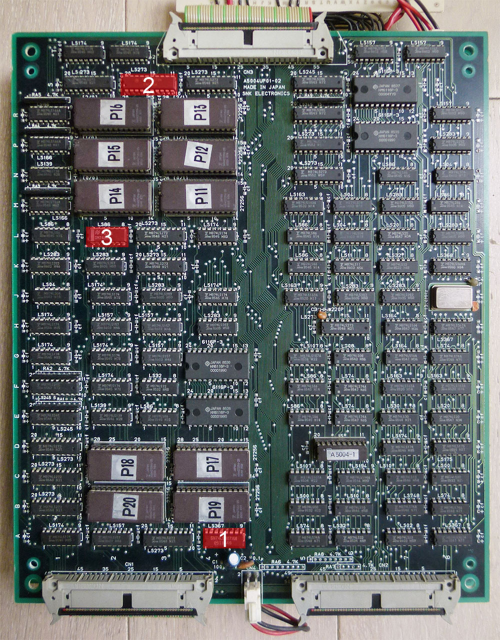
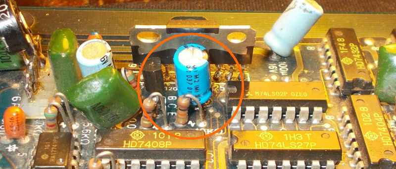
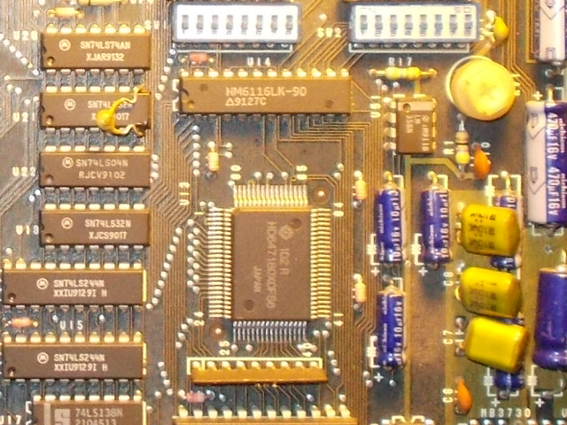
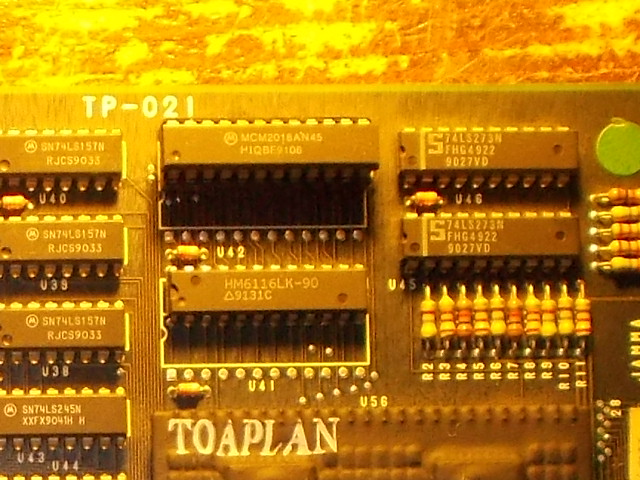
As in previous repair, I already knew where to look at.Sprites ROMs are located on video PCB in form of 8 2764 devices on a small piggyback board:
![]()
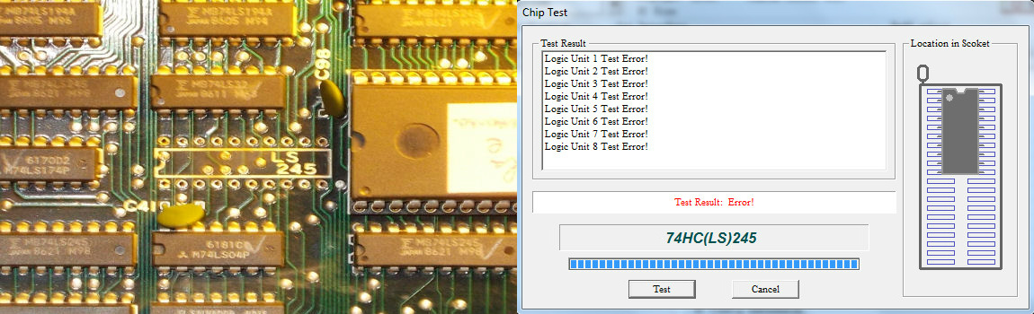
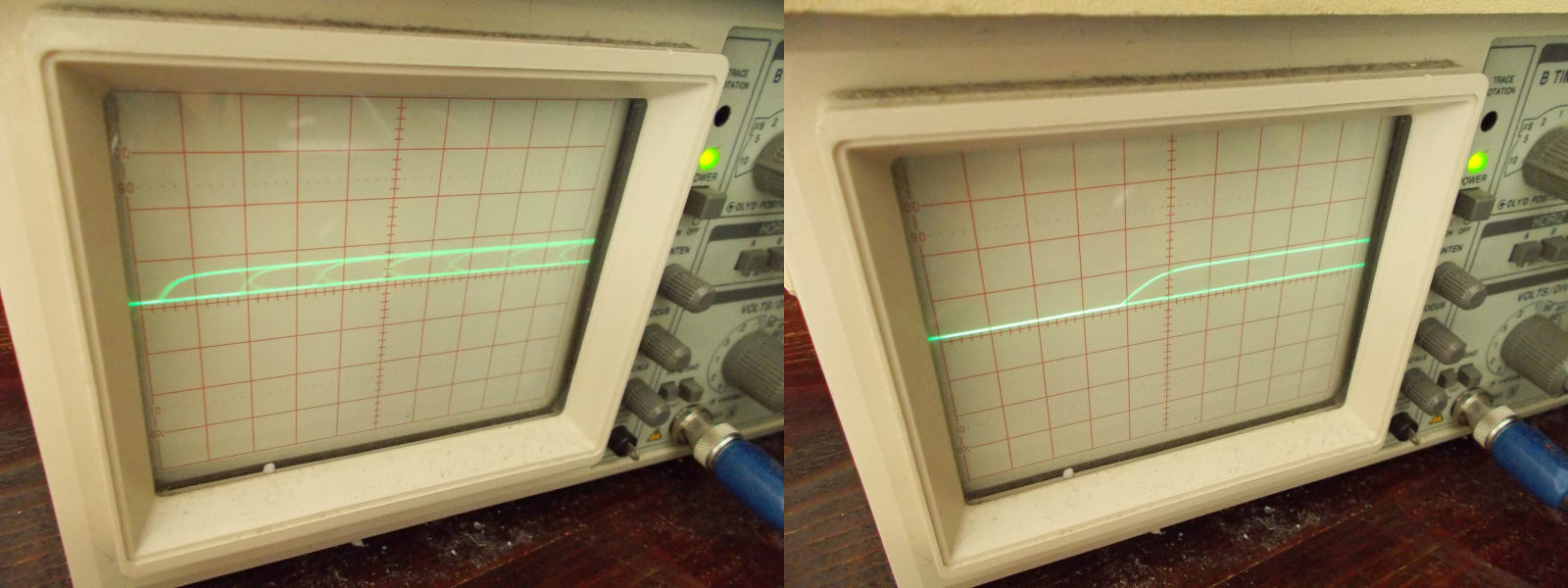
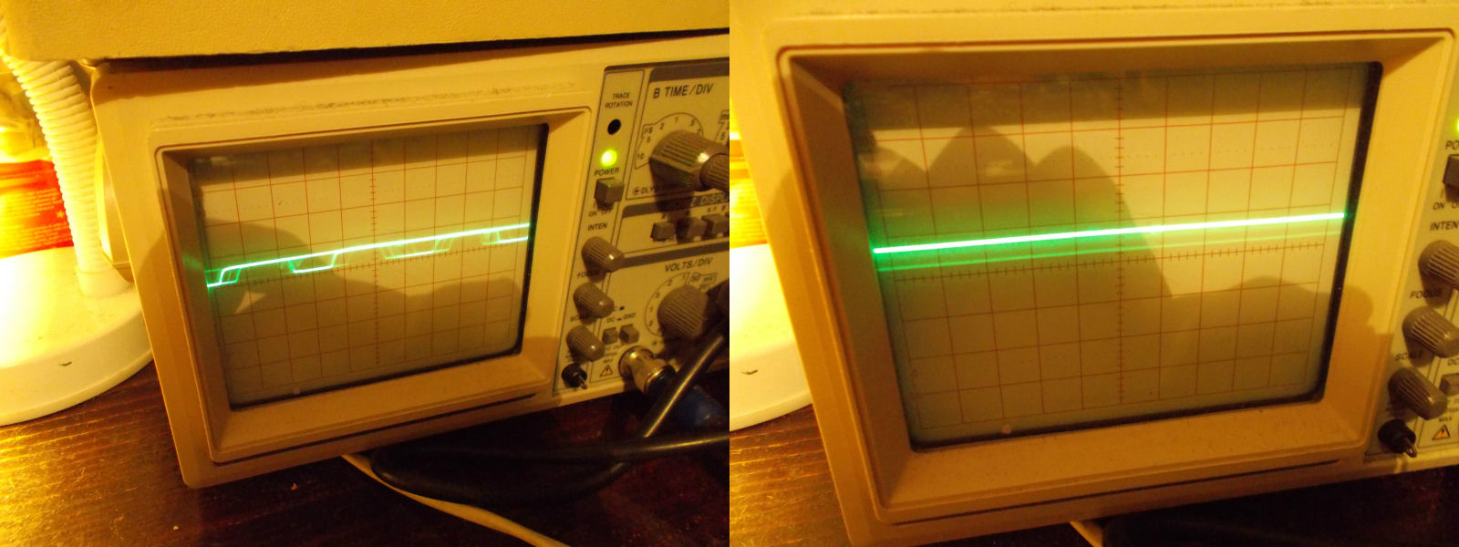
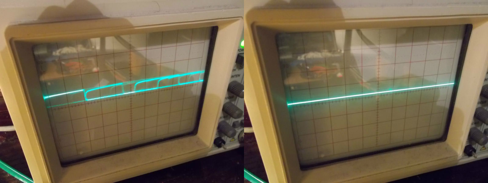
Data of these ROMs are latched by some 74LS273, when I went to probe with my analog scope the one @E20:
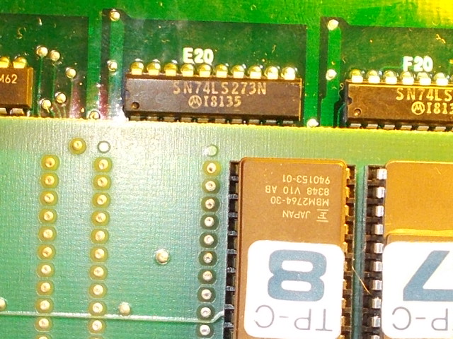
I found all outputs were bad compared to inputs:
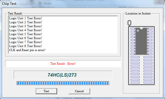
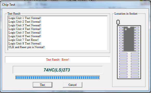
The IC failed when tested out-of-circuit:
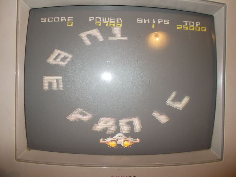
The sprites looked much better but still not perfect:
This is how it should be (MAME screenshot):
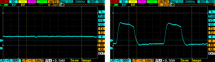
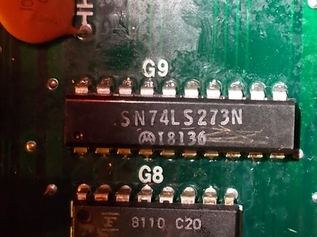
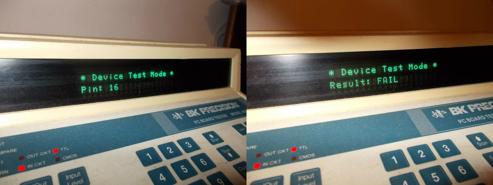
So I went to probe other ICs with my BK560A in circuit tester which reported trouble on pin 16 (output) of another 74LS273 @G9:
This was confirmed also by my scope, the output pin 16 was stuck low compared to its input pin 17:
Once desolder and tested out-of-circuit, the IC failed in that specific gate:
A good IC restored sprites:
Another Tube Panic (I hope the last…) fixed!