I had this rare Irem Ken-Go PCB (an undumped version included in latest MAME release) from my friend Joachim for a repair:
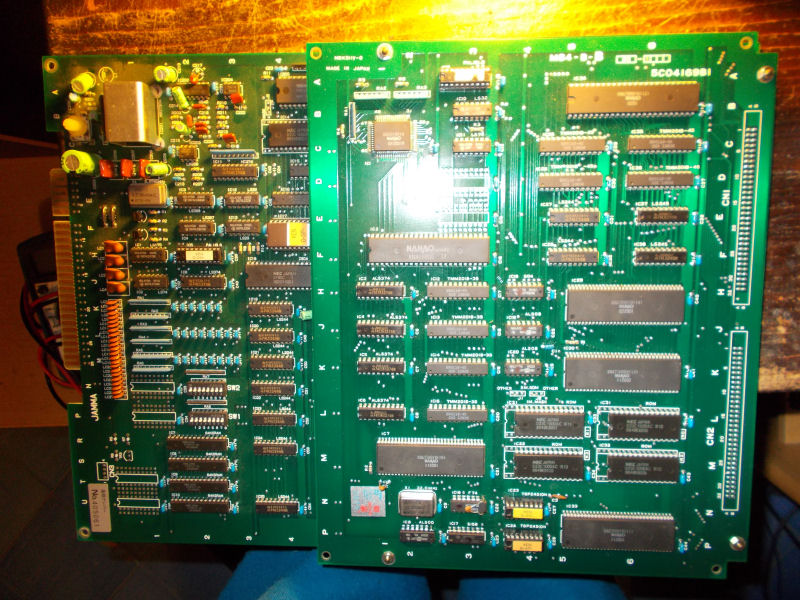
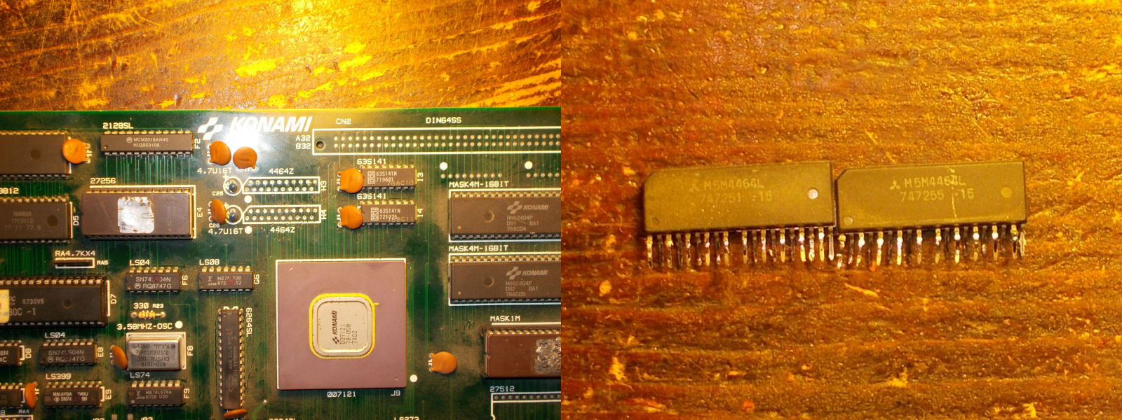
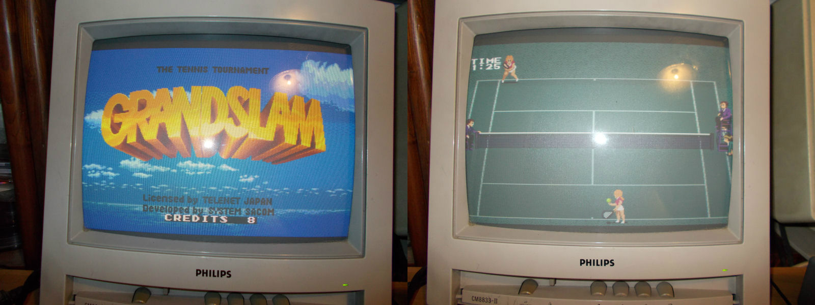
The board played fine except for an issue where all sprites were formed but missing all colors appearing like black shape:
![]()
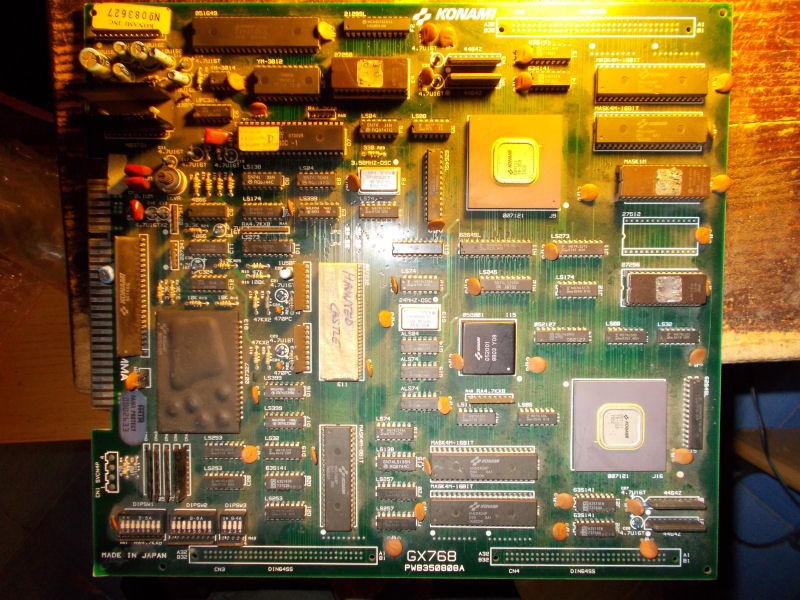
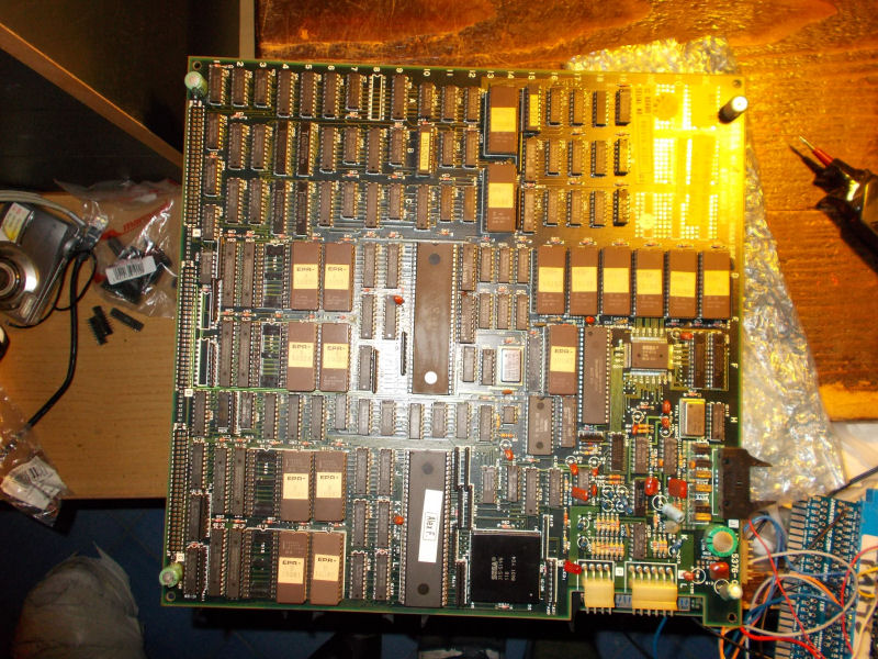
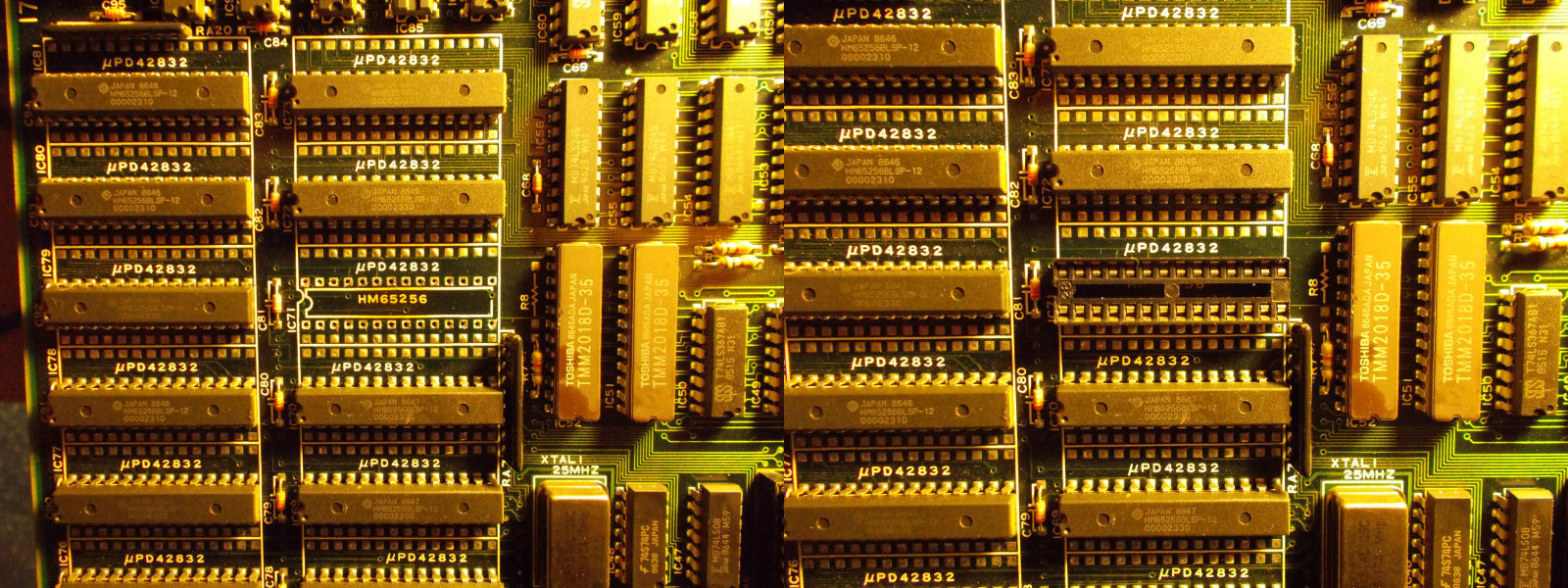
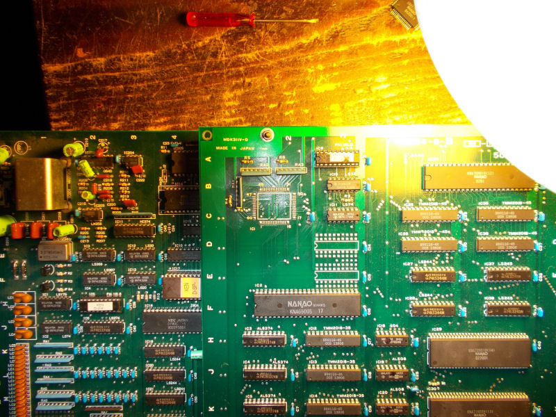
Sprites generation circuit is located on top board where some customs lie:
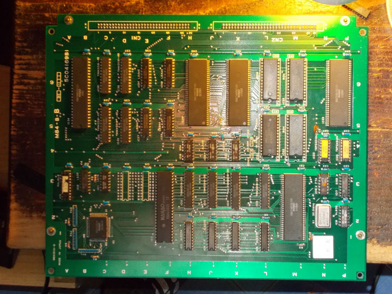
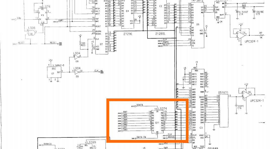
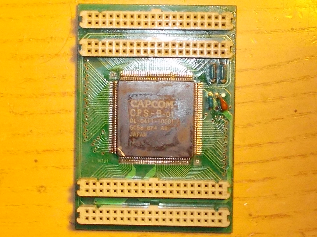
Documentation for this specific game was not available but luckily I could know function of the various customs by looking at the R-Type schematics and so identity the one involved in the sprites palette generation:
![]()
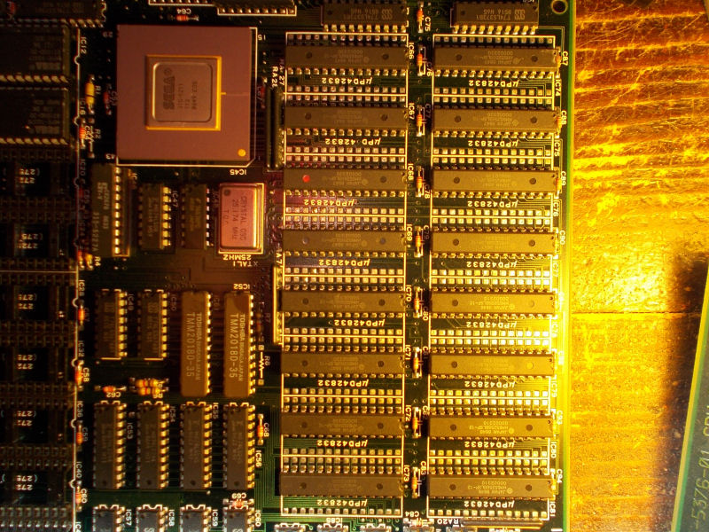
The custom itself was marked ‘KNA91H014’ in 60 pins QFP package:
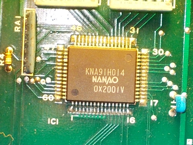
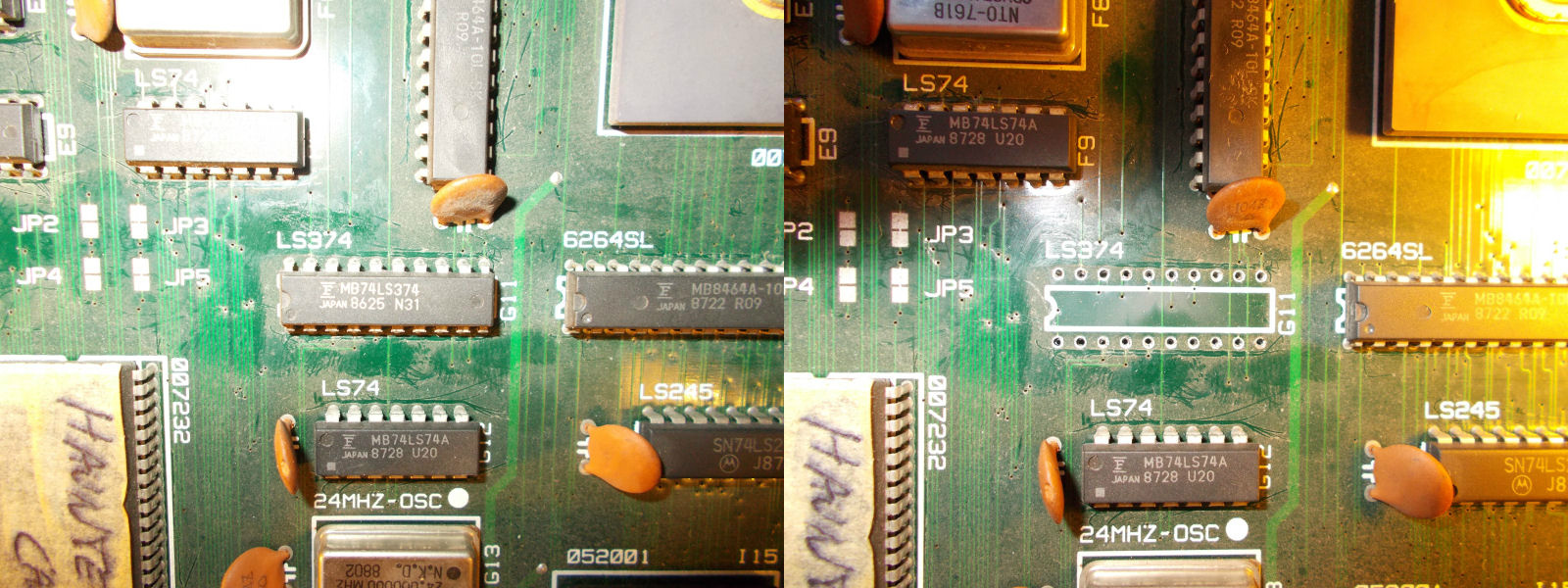
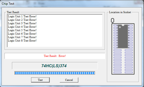
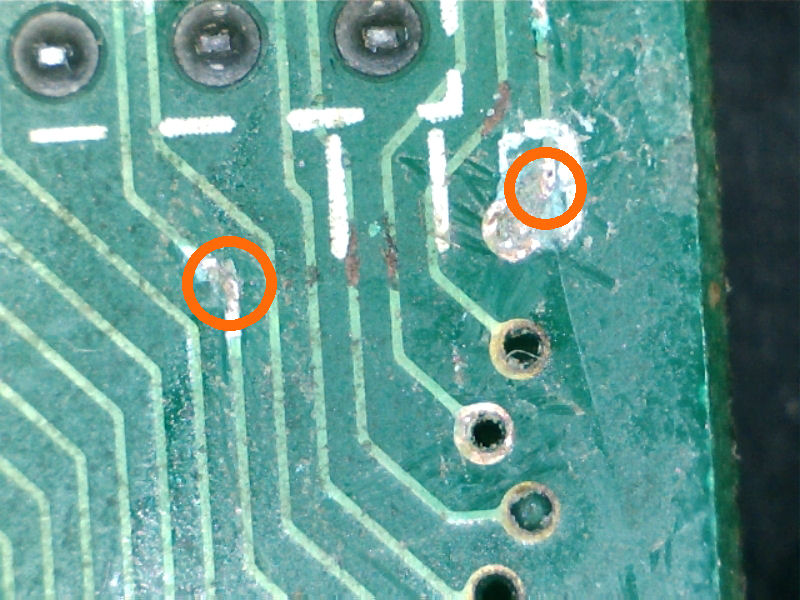
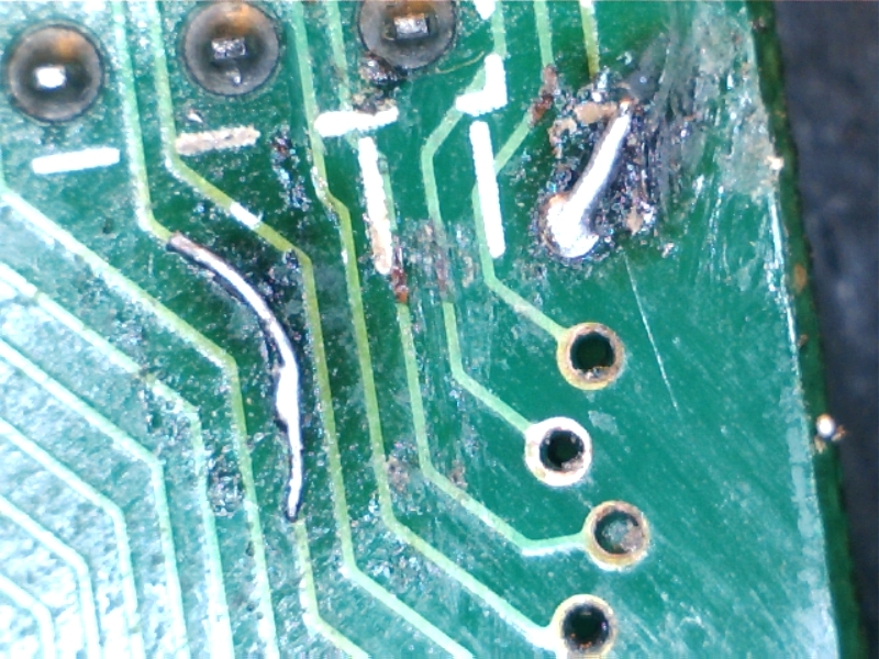
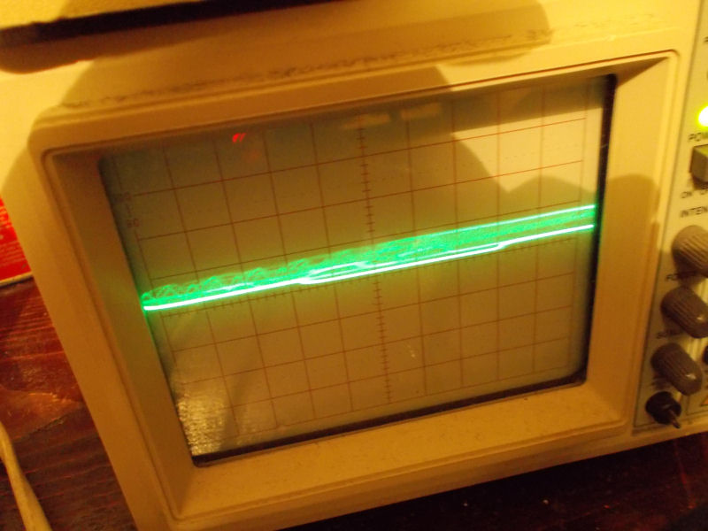
Probing it revelead that inputs were fine but outputs had irregular signals:
So I opted for replacing this custom (taking a good one from a dead Vigilante board) :
This was the right move since sprites were correcly restored:
![]()
End of job.