Let me preface this by saying I’ve been really lazy about blogging my repairs this year. I found some free time today and decided now is a good time to post some of my accomplishments. All of the following repairs were performed through out 2016, but not documented until now. Enjoy!
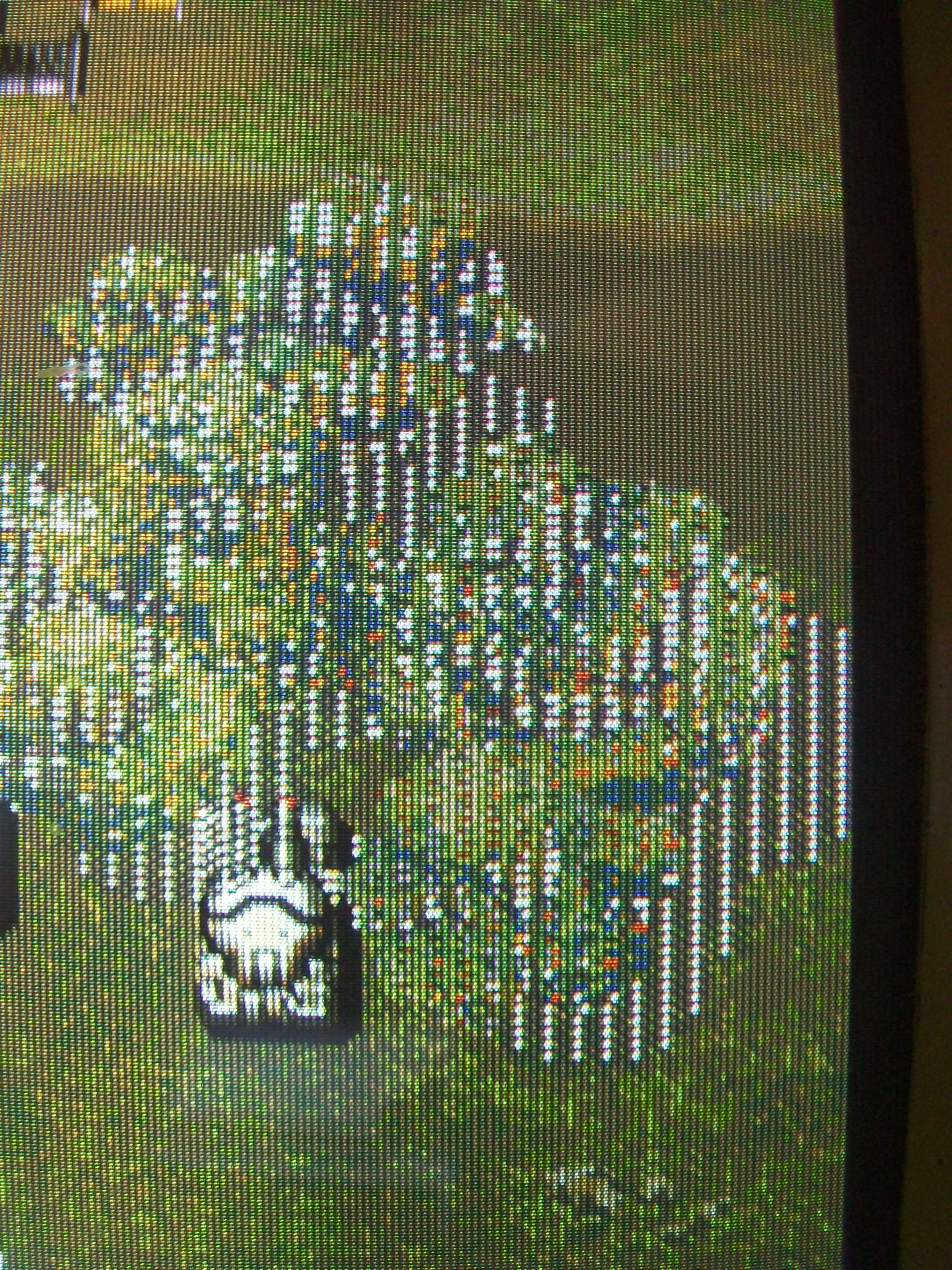
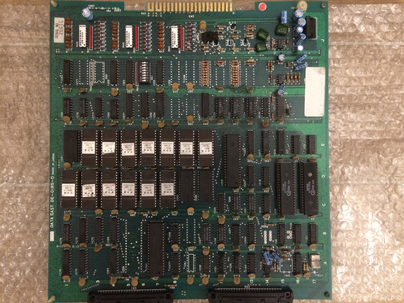
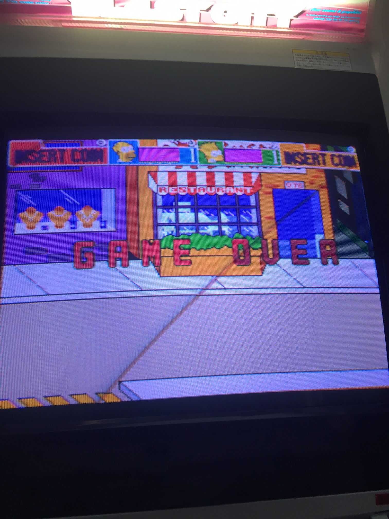
I received a faulty Simpsons PCB off of ebay for a reasonably good price. It was sold simply as not working with the faults not described. Upon receiving the board, I observed it was in very good condition and a worthwhile repair candidate. When I fired t up, the graphics were REALLY bad! As you can see, the backgrounds and most of the sprites are missing:
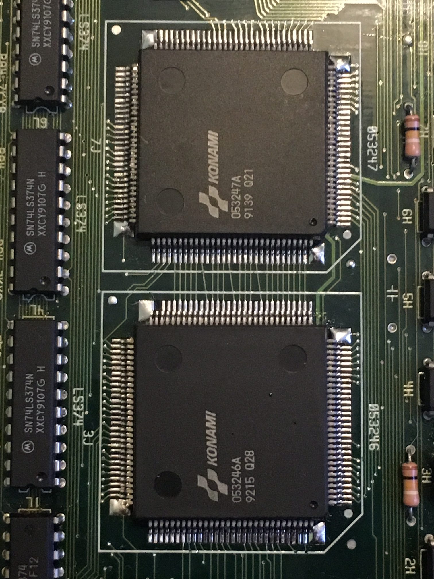
I was able to run the rom test and self test, all IC’s reported as good (so I was confident there is not a ram or rom issue at hand). I turned to the mame source code to better understand what each of the Konami Hybrid IC’s are responsible for in the graphics section. I learned that 053247 and 053246 are responsible for sprite generation, and decided they would be a good starting point. Fortunately I had a dead XMen parts-PCB with both of these Custom IC’s present. I started by swapping 053246 with the donor from XMen. As you can see below, we’re getting better! But its still not fixed… Backgrounds are rendering but the sprites are now missing.


I decided to move on to the 053247 IC, and attempt swapping that next. I learned that these IC’s work in tandem, and if one is bad, there’s a chance the other is also bad.

With both IC’s changed from the donor Xmen board, all graphics are restored!!!

Repair complete, game now plays 100%. I don’t dare imagine the abuse this PCB received that took out BOTH custom IC’s, but I’m glad its ready to play on. Another gem saved from the scrap bin!