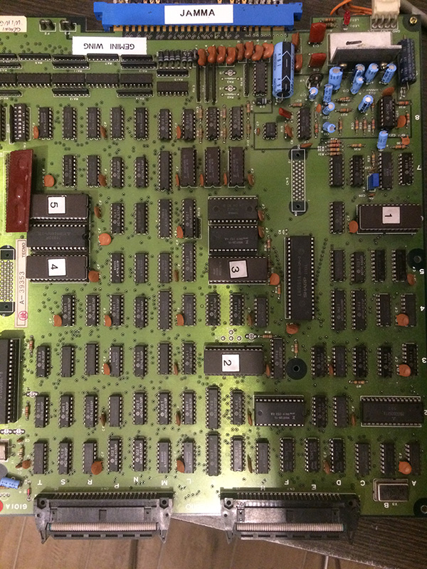
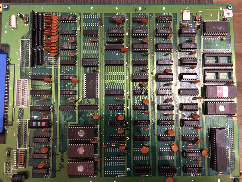
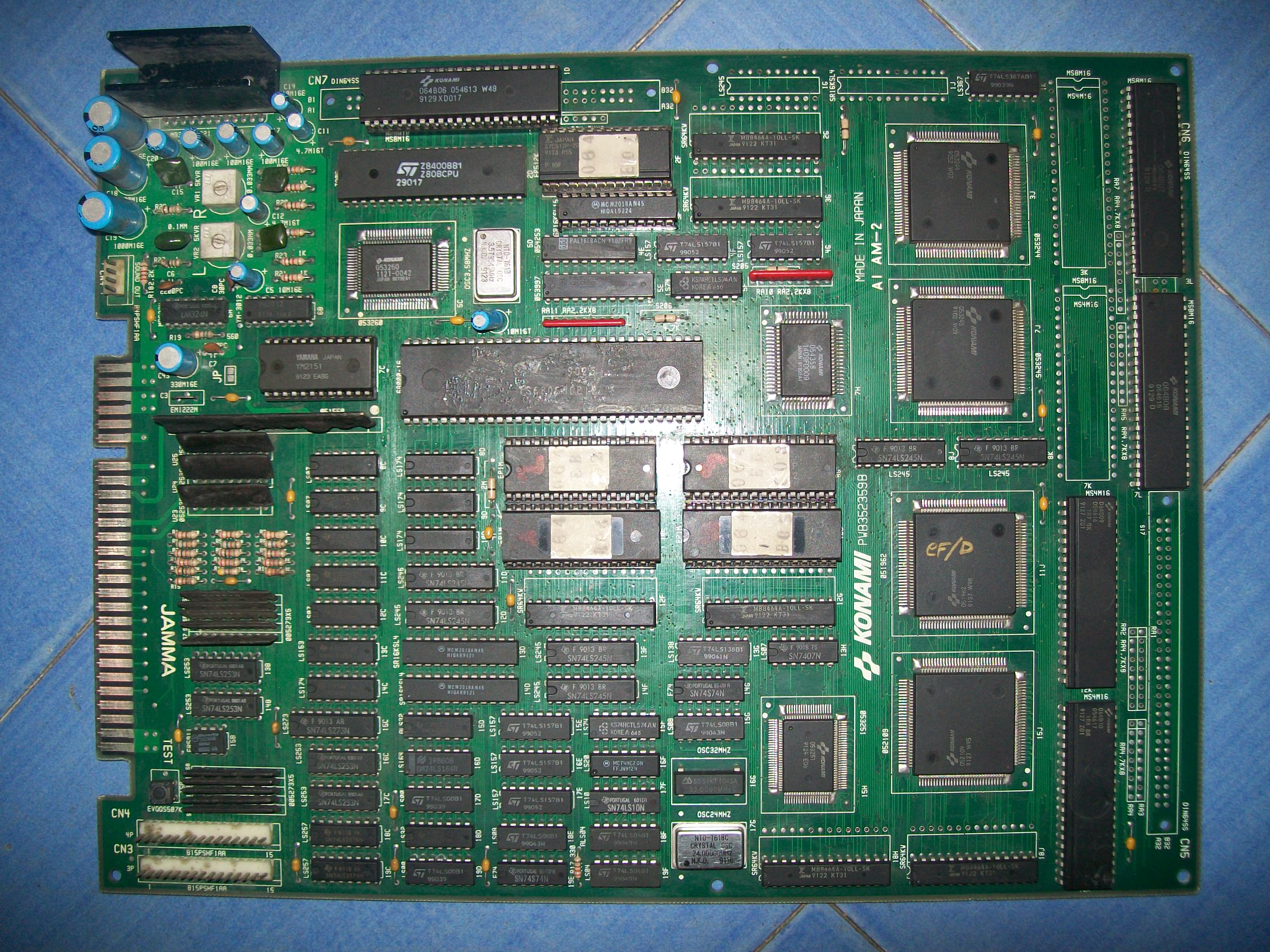
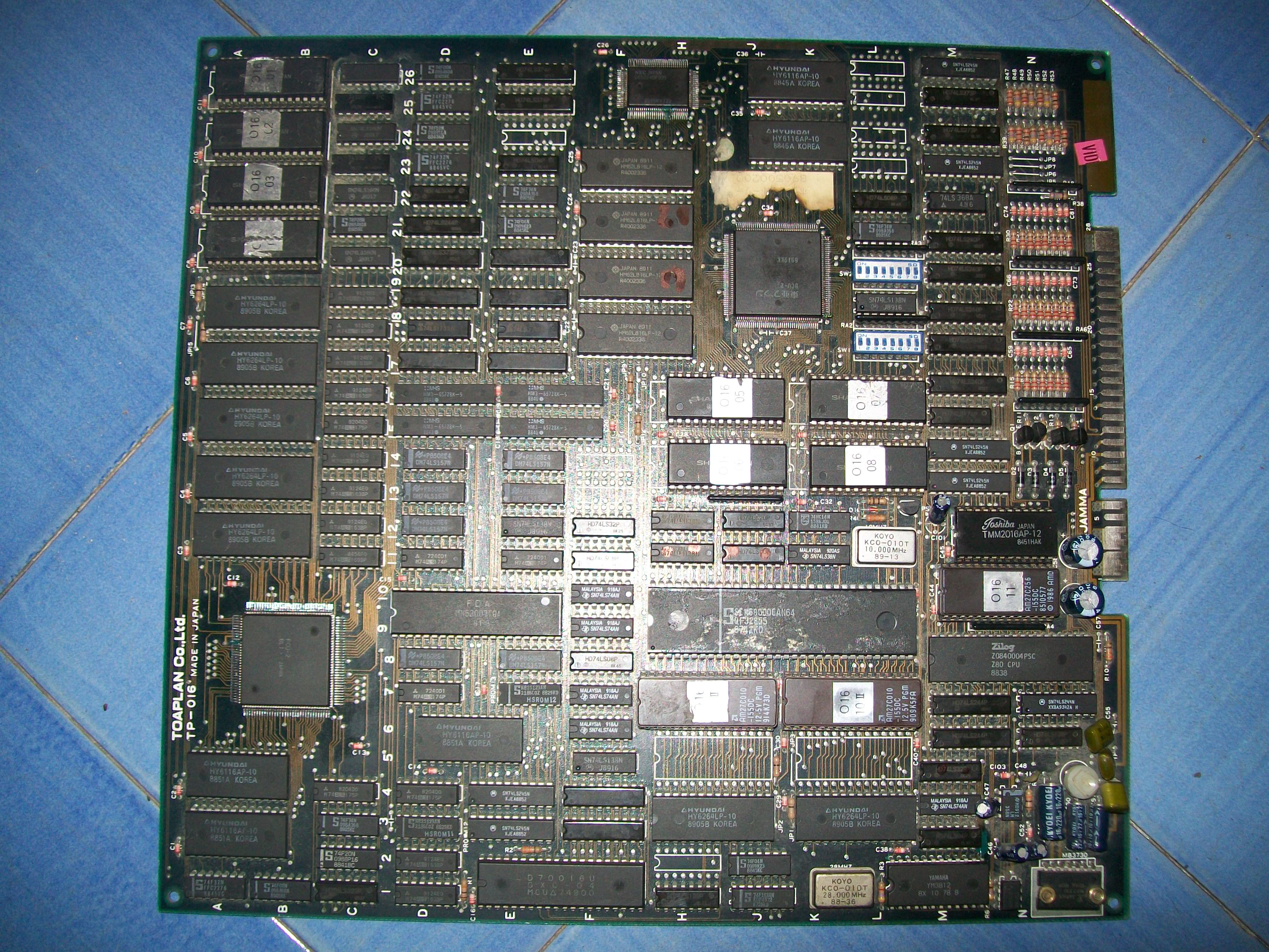
Received a Lightning Fighters for a repair.Board was in bad shape, some ICs were missing and solderside had a lot of scratches:
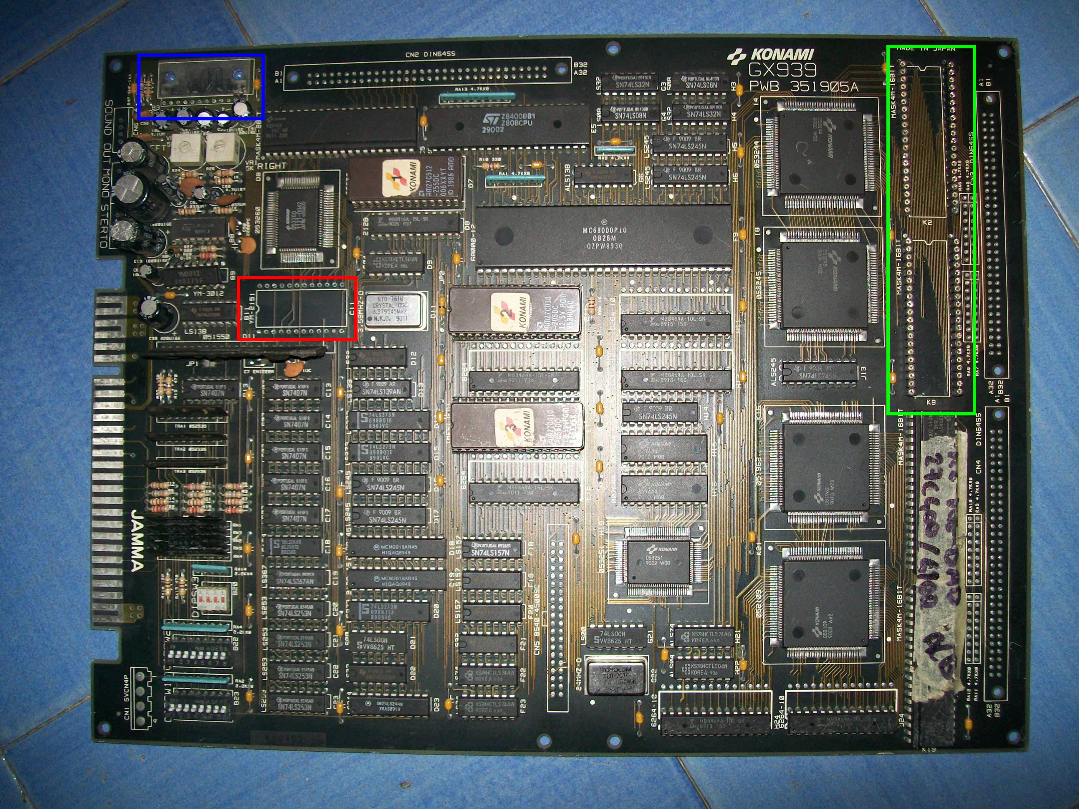
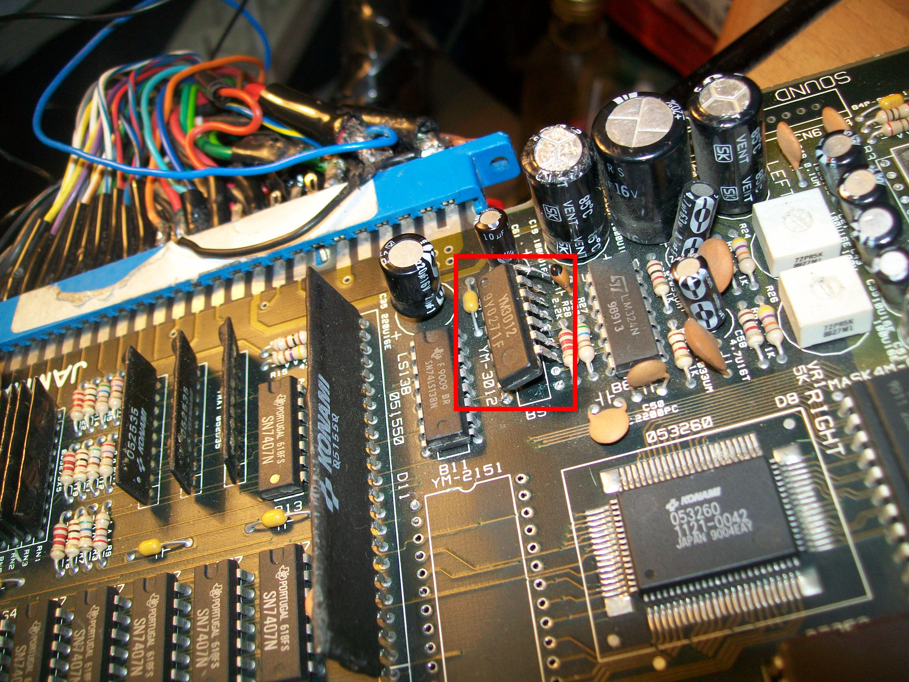
In the details, it missed two 4Mbit MASK ROMs used for sprites (but rounded machine-tooled strips were installed in place of them), the YM251 and MB3722 amplifier and its heatsink.Besides, the YM3012 DAC was partially desoldered and damaged:
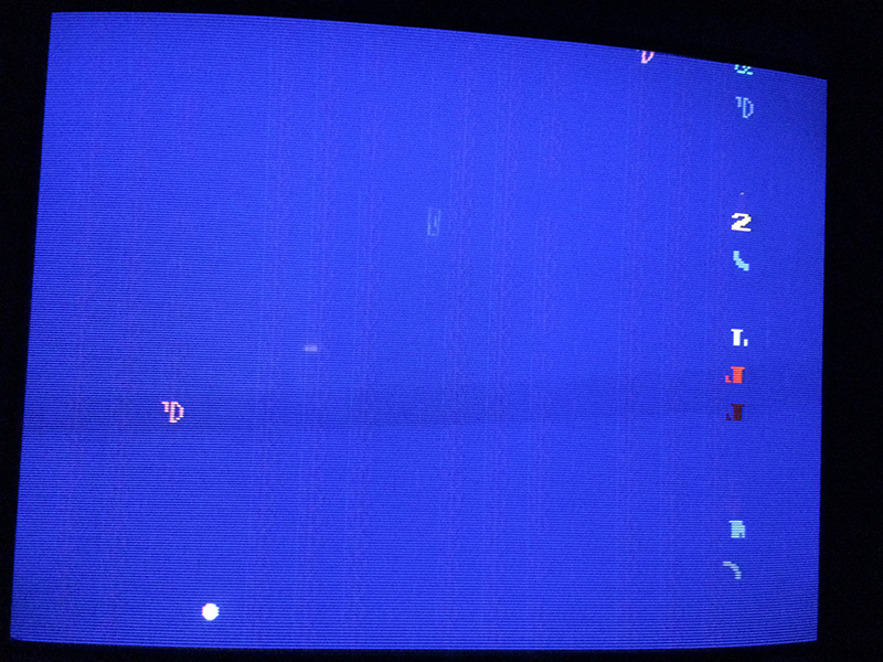
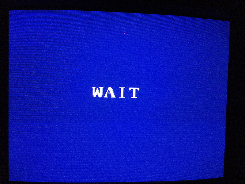
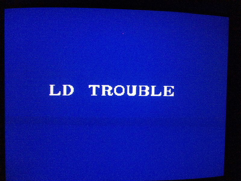
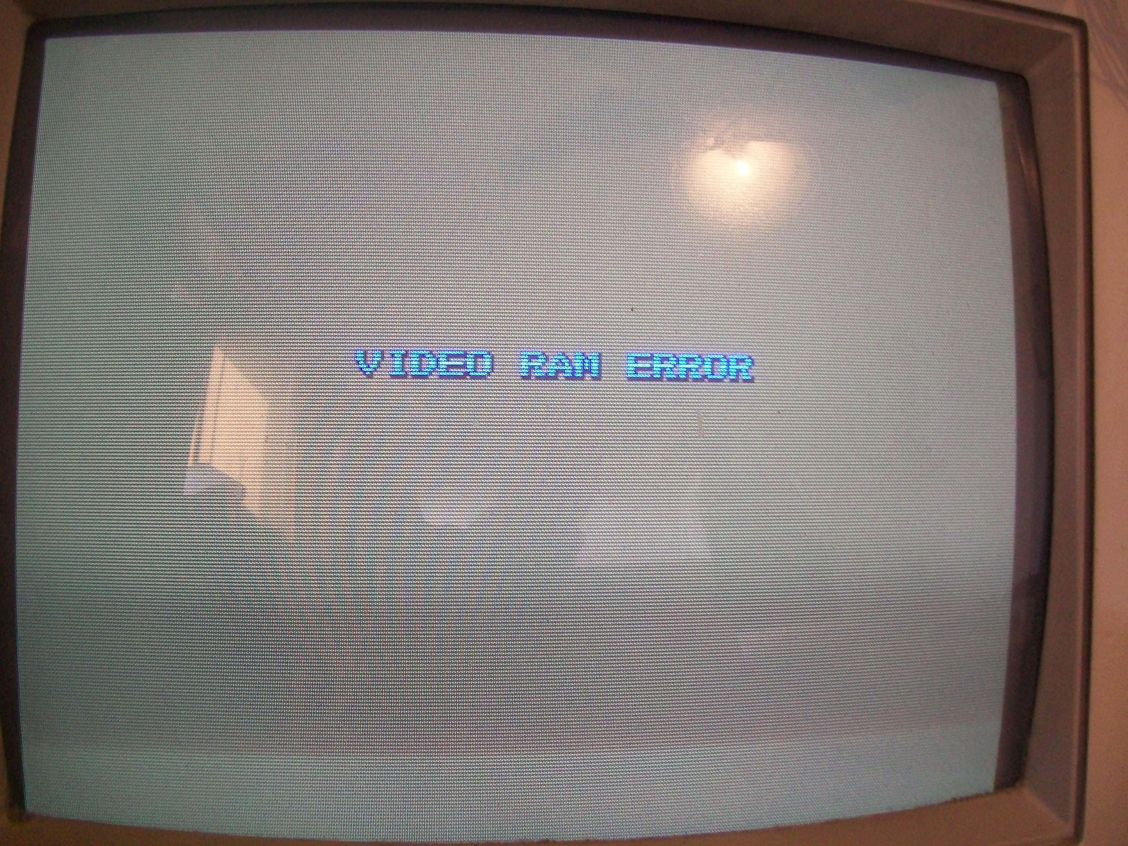
At power up I was greeted by the typical flashing blank screen, board was constantly resetting due active watchdog circuit:
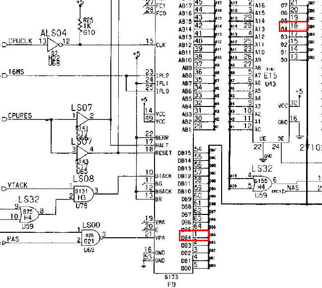
This meant that main CPU program code couldn’t be properly executed due a probable problem in 68000 busses.With the help of schematics I went to check this circuit and found a missing connection between data line D4 (pin 18) of the program ROM @E15 and corresponding data line (pin 1) of 68000:
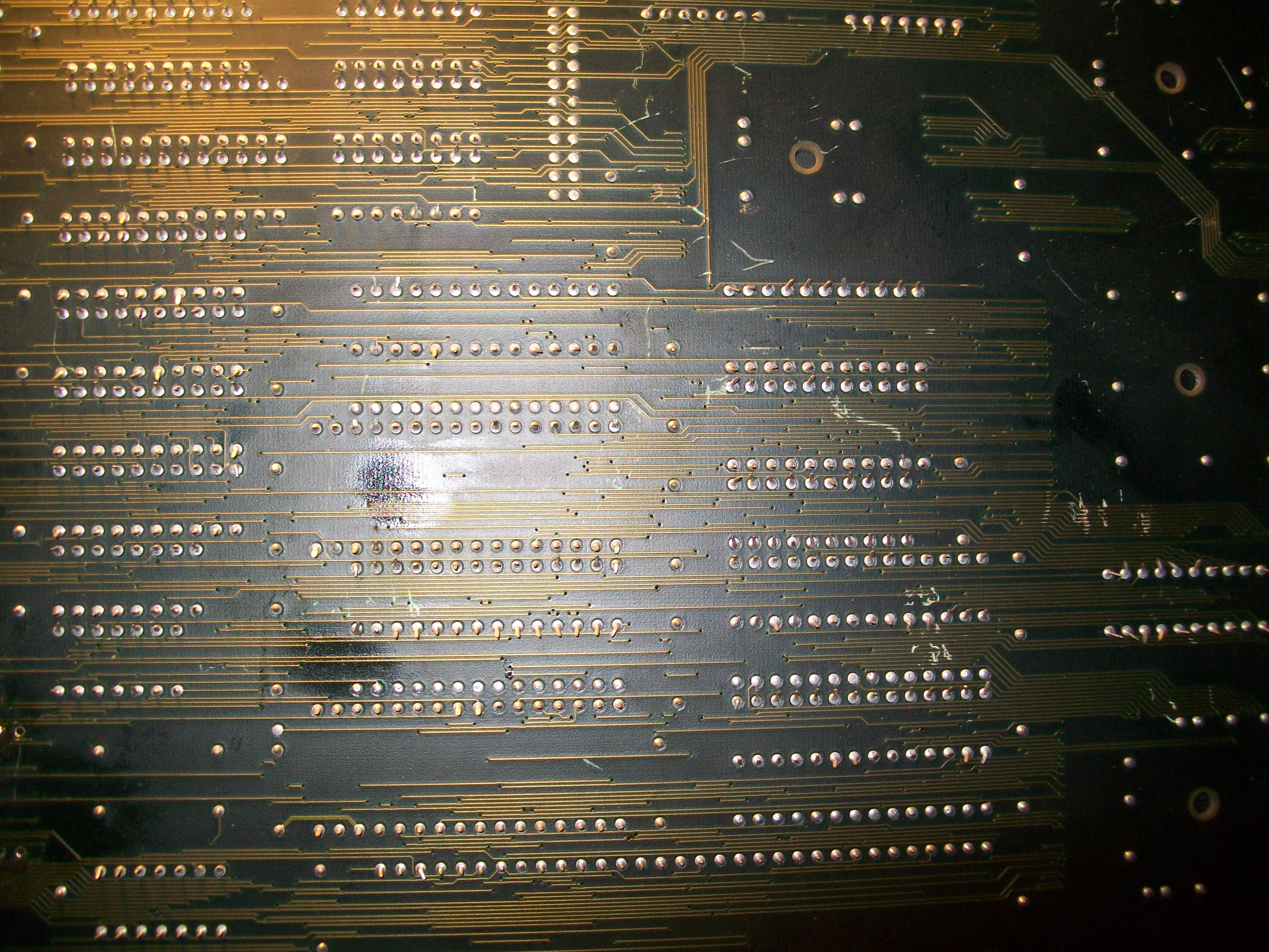
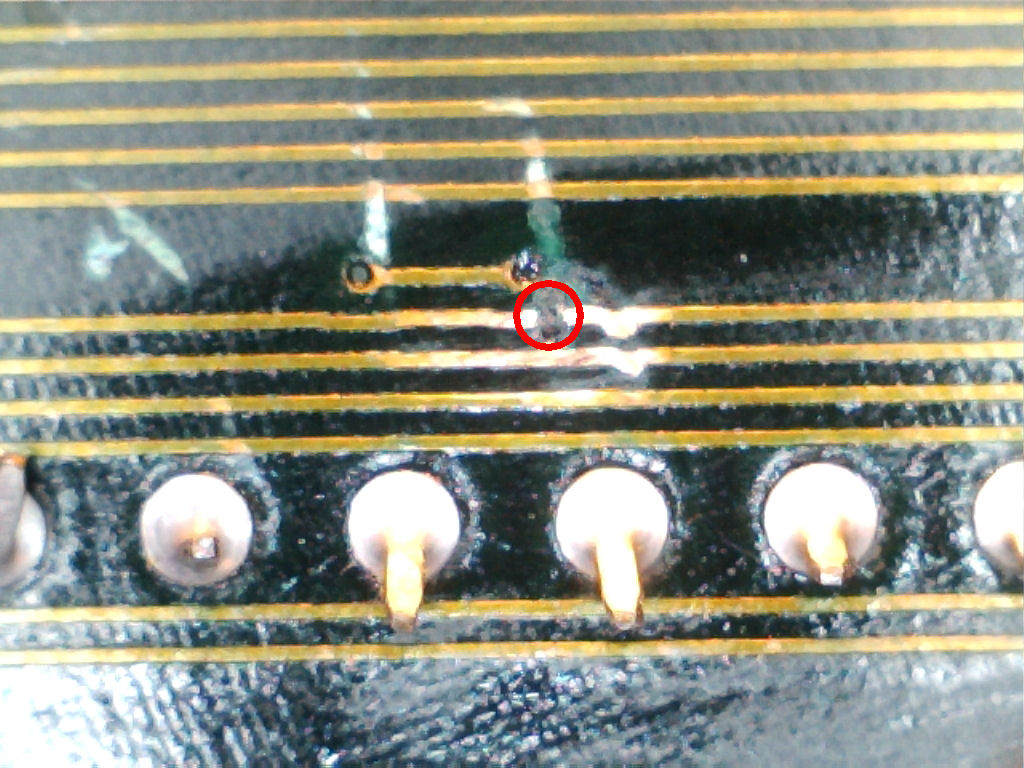
Tracing back both pins I found a broken trace on solderside :
I restored the connection and board successfully booted with obviously no sprites and sound due missing components.I decided to fix the graphics for first so I burned two Macronix MX27C4100 EPROMs (same pinout of 27C400) to replace the two missing 4Mbit MASK ROMs @K2 and K8.In this way sprites reappeared but they were glitchy:
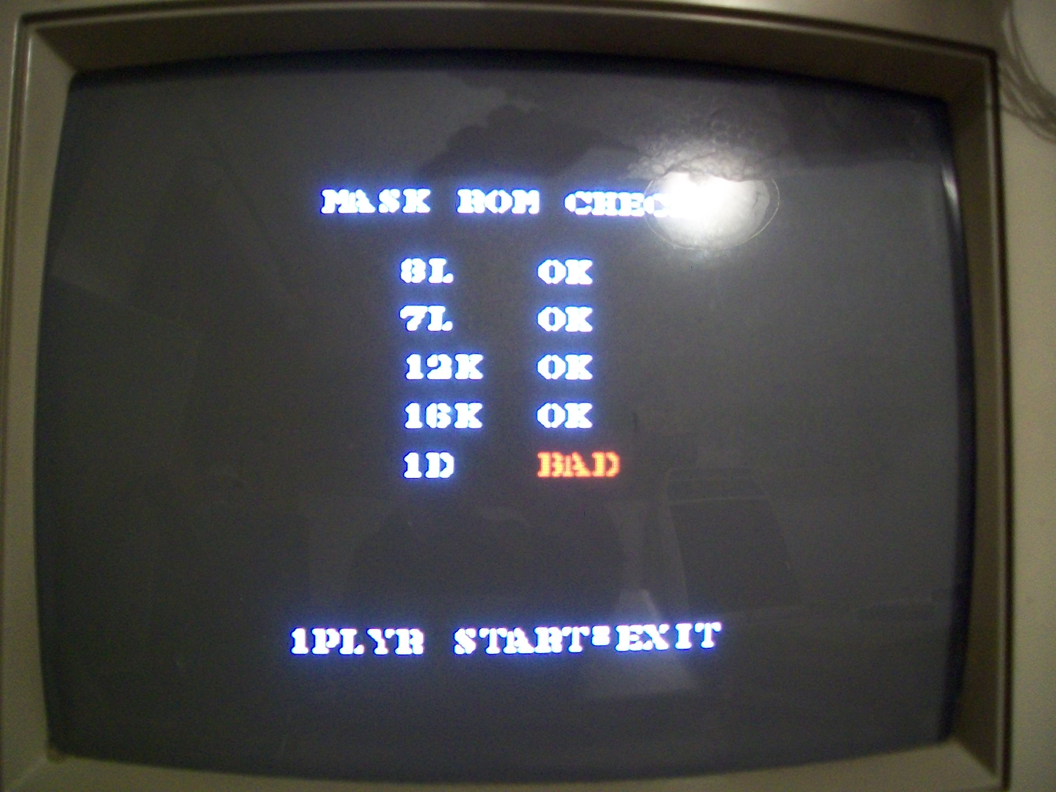
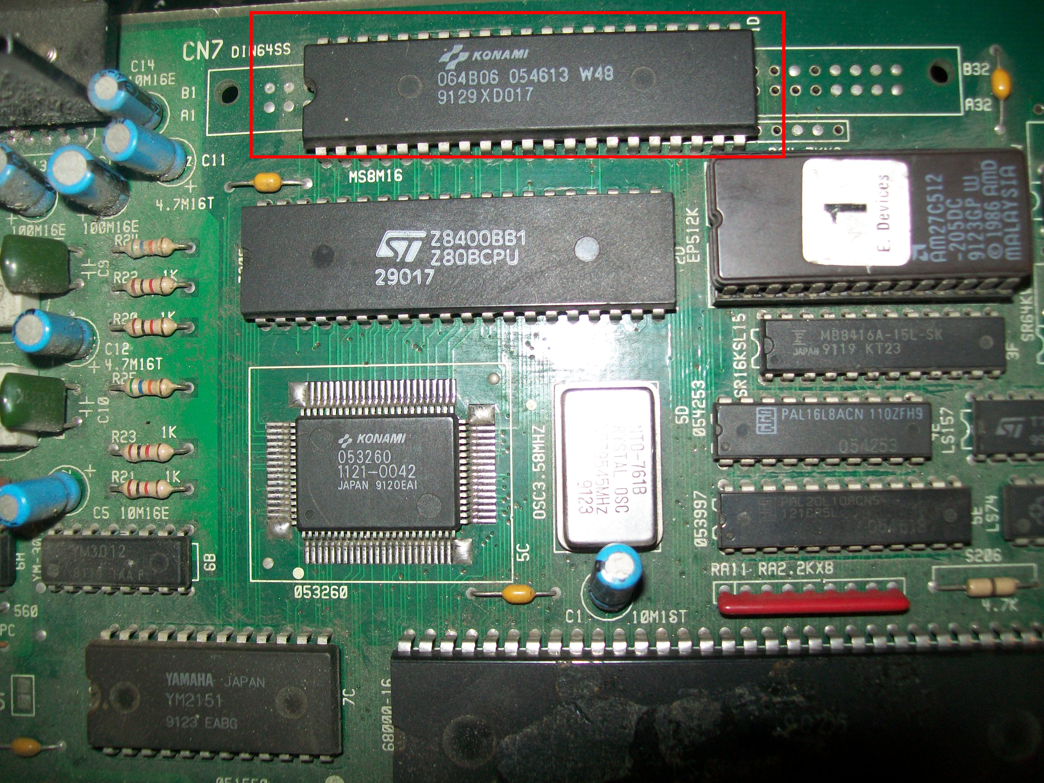
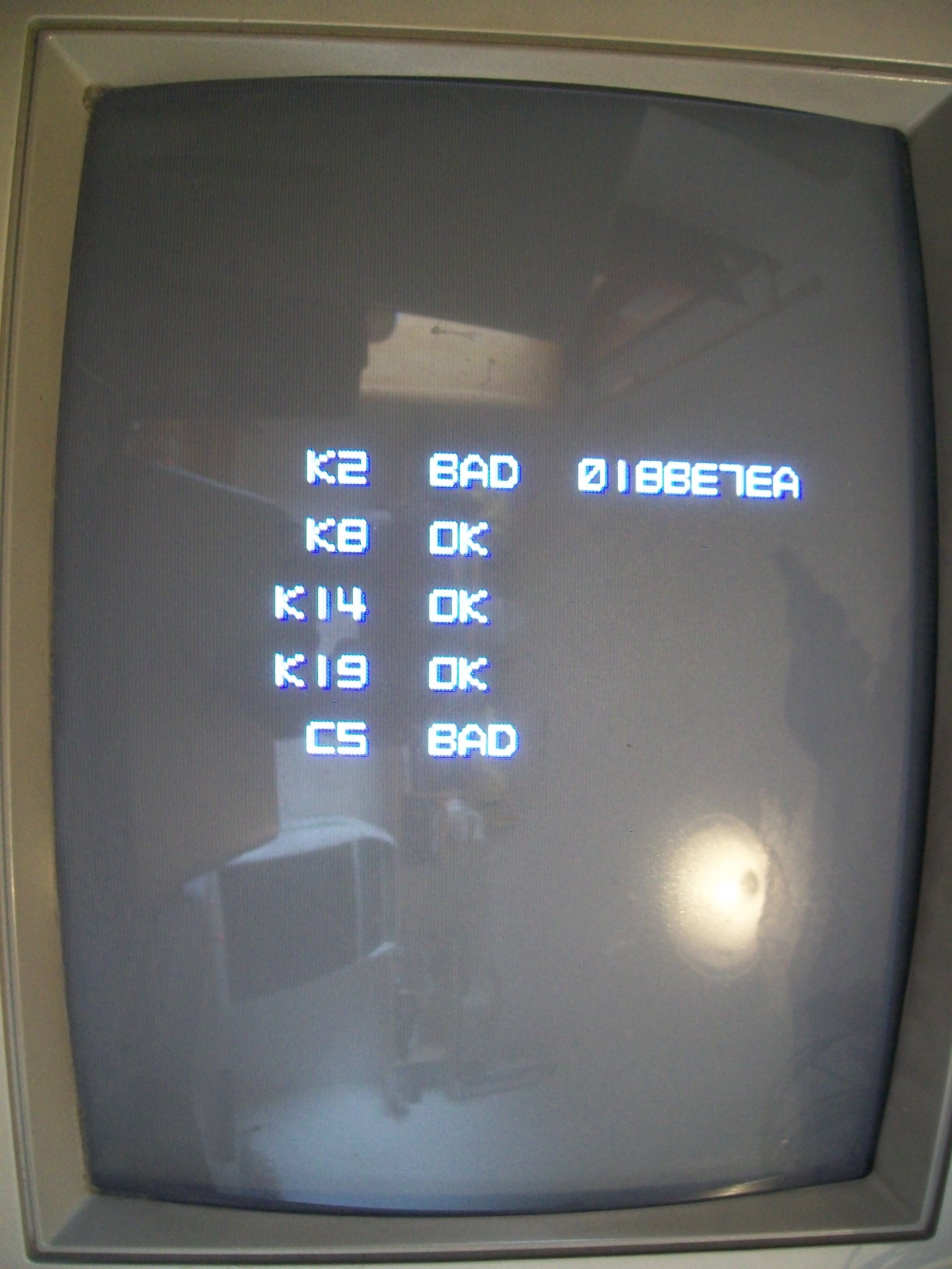
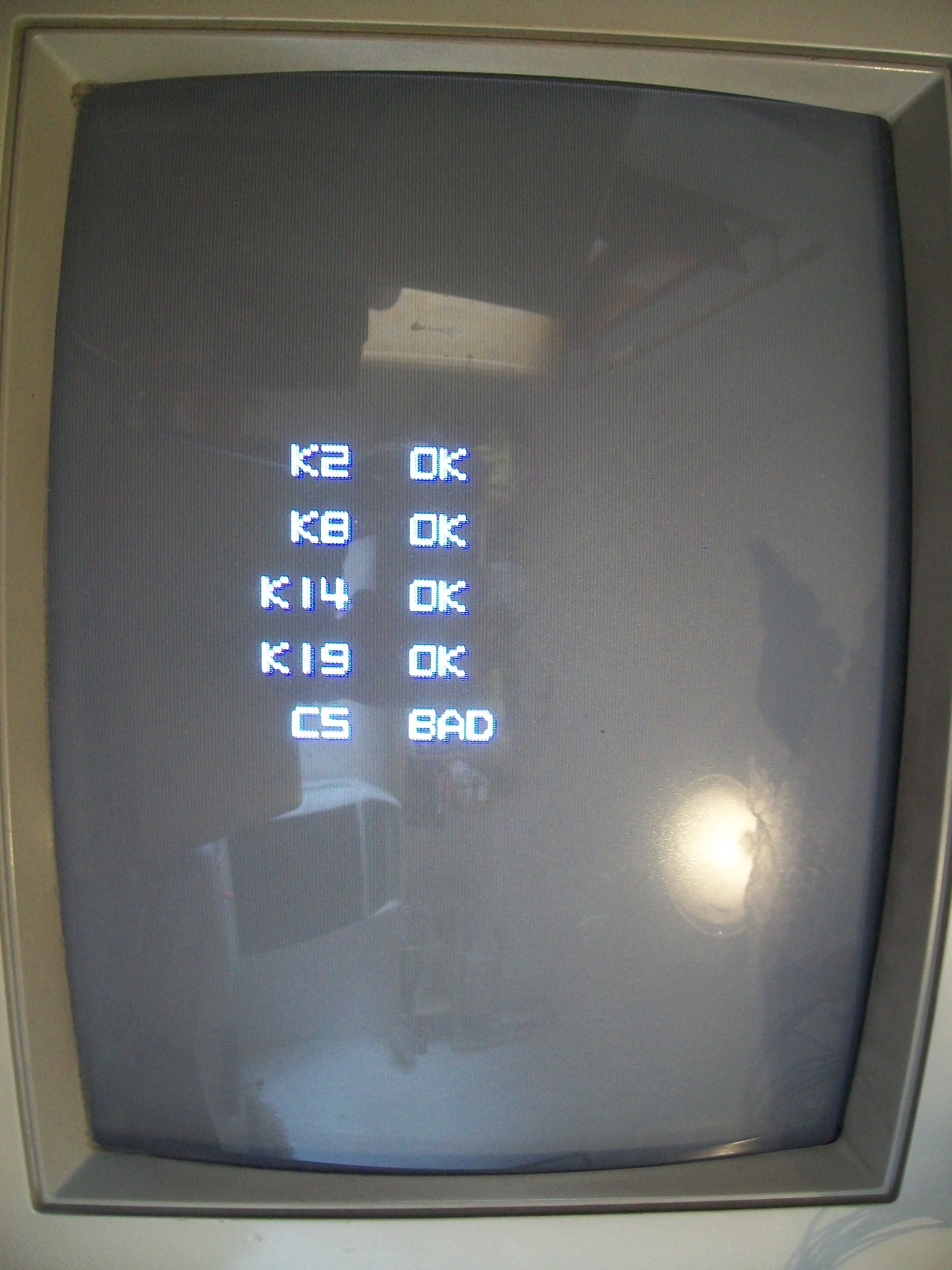
MASK ROMs check reported a bad device @K2 (and another one @C5 but this was due the missing YM2151 as I discovered later)
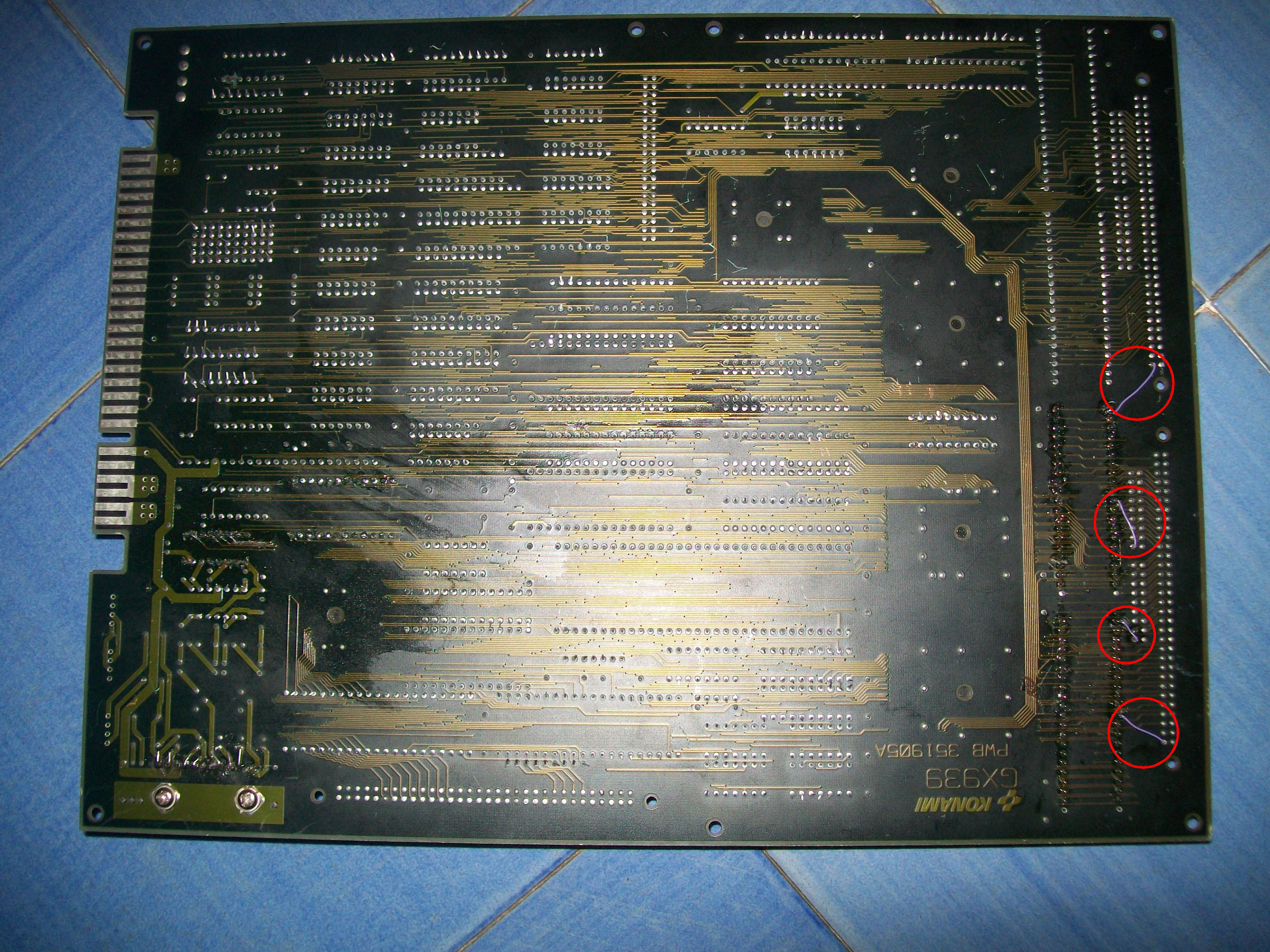
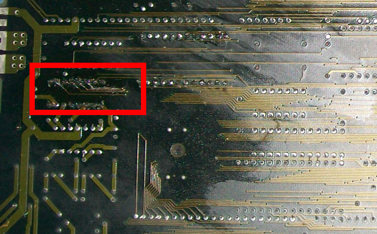
Again I checked connections of the device @K2 against schematics and found intermittent contact between pin 21-31 and VCC (pin 31 of a 27C400 EPROM must tied HIGH to enable the Word-wide organization of data).Who put hands on this board removing the two MASK ROMs and installing round machine-tooled managed to rip off the rivets which are inside the holes, this explains the poor contact of the two pins.I reinforced the connections with some AWG30 wiring them between the solderside of the pins and alternative VCC points :
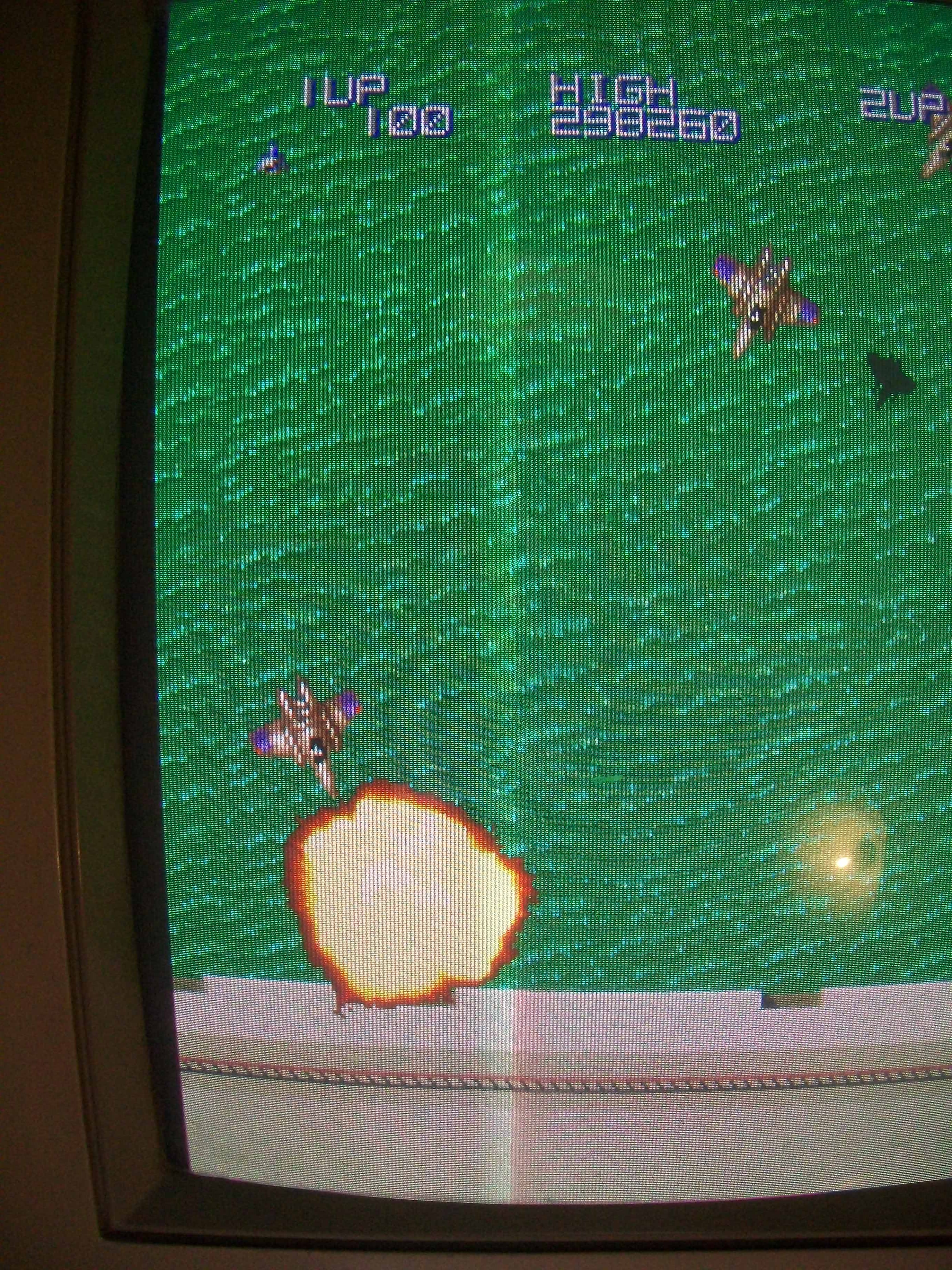
Sprites were good now but still not perfect, some of them (like explosions) had jailbars: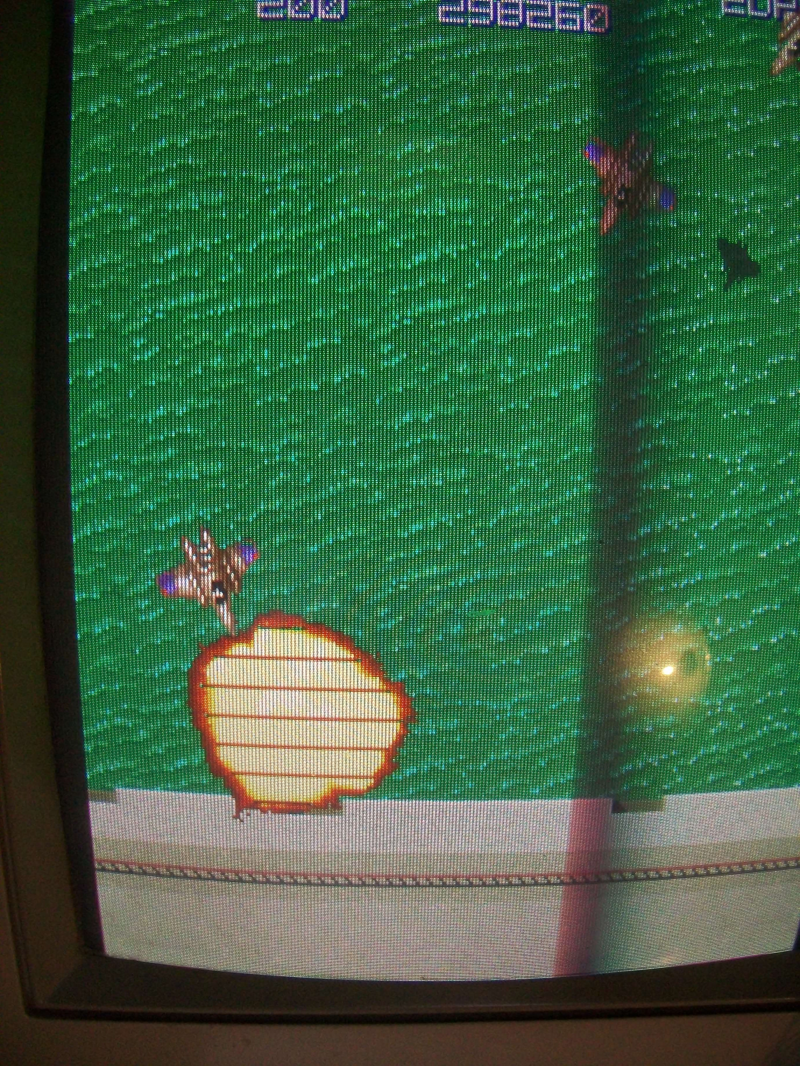
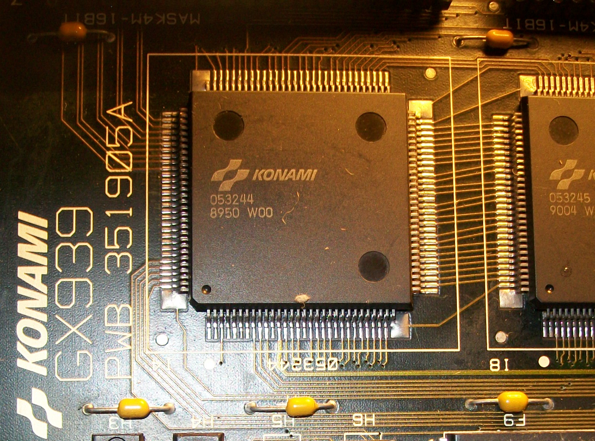
I reflowed the ‘053244’ custom ASIC sprites generator:
Jailabars were gone:
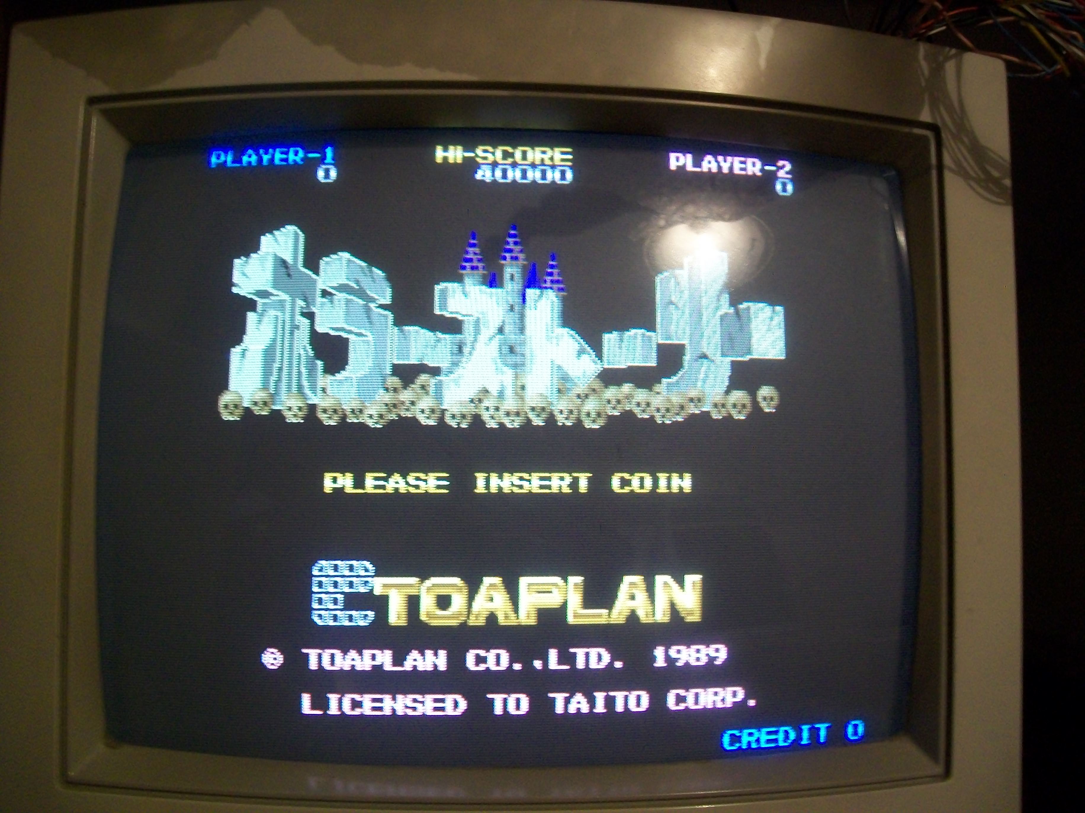
All graphics were pefect now, confirmed also by the MASK ROMs check:
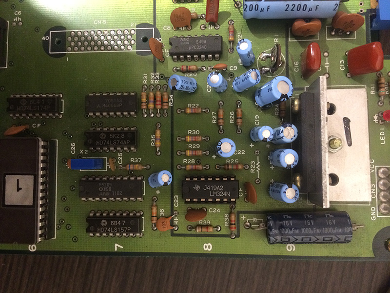
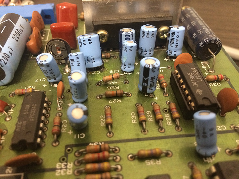
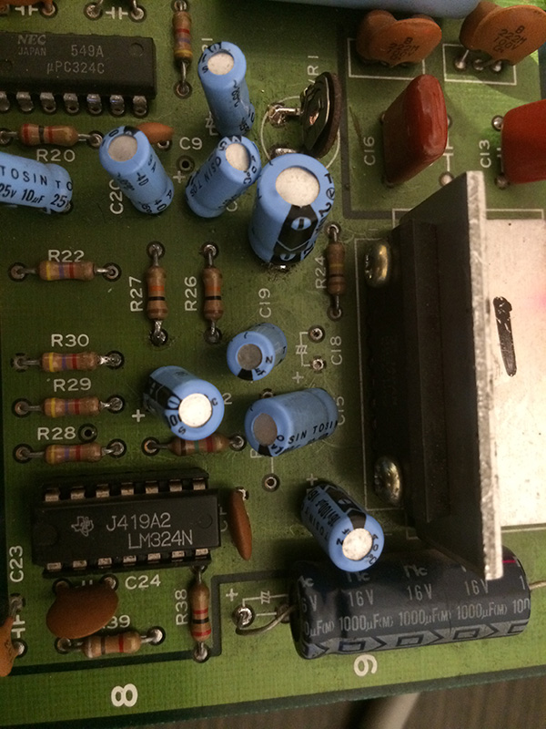
So only the sound needed to be restored.l fitted all the missing componens (the YM2151 and MB3722 amplifier with its heasink), removed the partially desoldered YM3012 replacing it and at same patched some broken traces on its solderside:
MASK ROMs check reported now success also on the device @C5 (which contains PCM samples)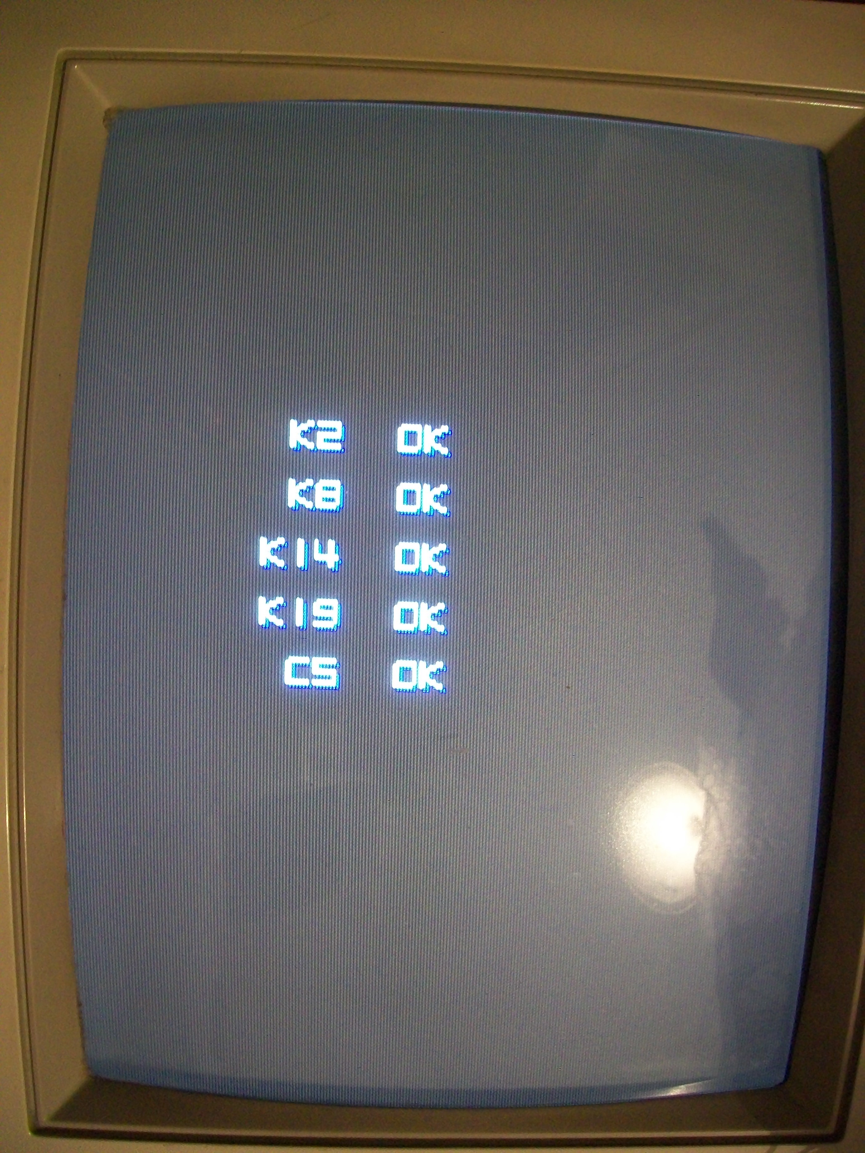
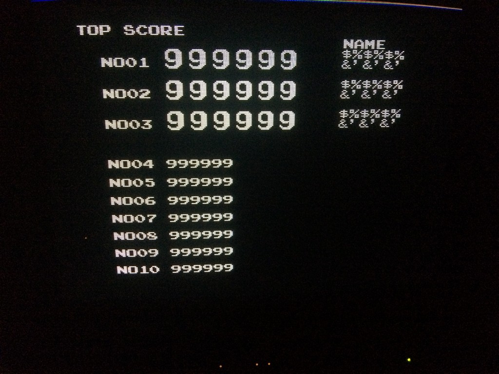
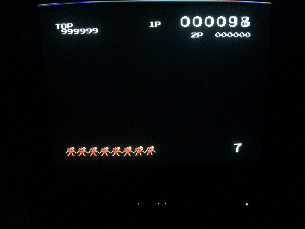
Once entered in game I had confirm that sound was fully working.Another PCB saved from certain death!