Return Of The Invaders repair log

 PCB Repair Logs, Repair Logs  Comments Off on Return Of The Invaders repair log
Feb 182017
 

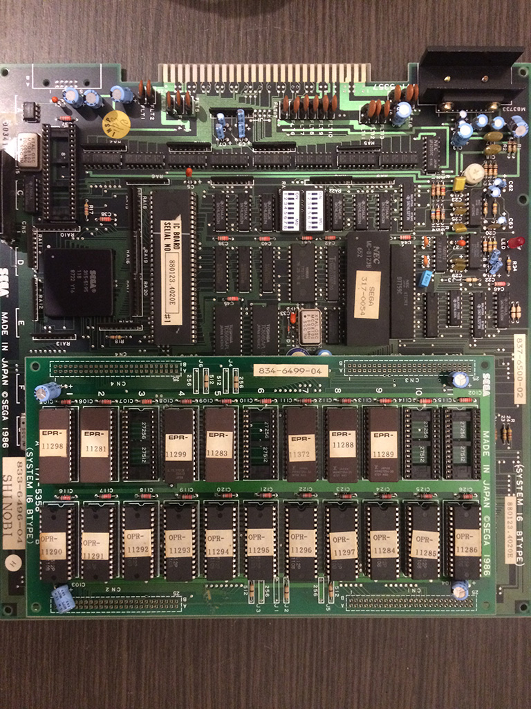
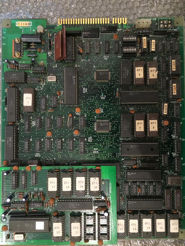
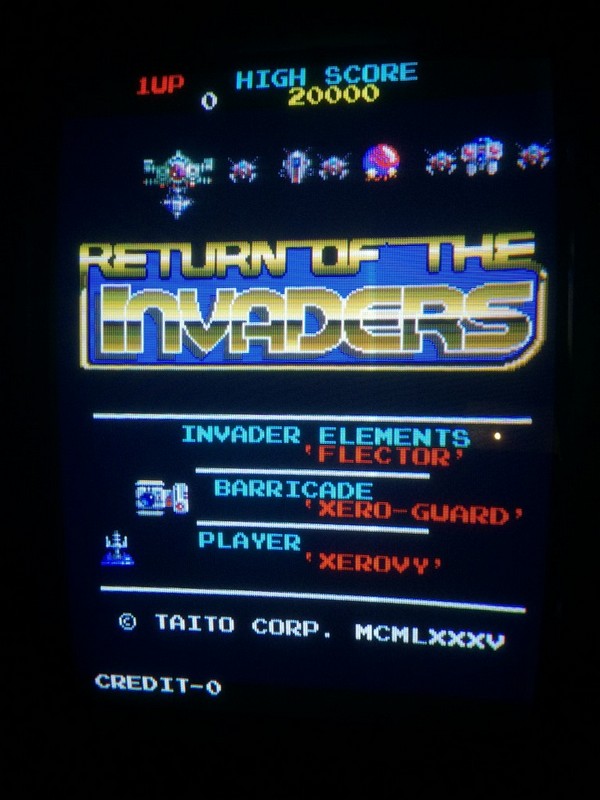
Recently I got hold of this favourite game of mine after a long searching. Apparently it is not so common nowadays, so when I saw a sales thread of this pcb  in faulty conditions from an italian arcade forum I took immediately the opportunity and bought it.

The seller posted a video in which the sprites where wrong and the red and blue components were inverted (this latter problem was caused by wrong wiring of jamma adapter)

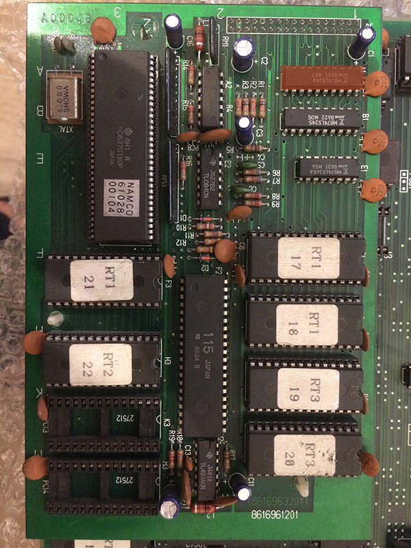
When the pcb arrived it was in very good conditions with all rams socketed in factory, therefore I immediately tested them out of circuit which unfortunately  were all good (so no easy repair 🙂 )

It had also an horrible hack on the sound amplifier, more on that later.

Therefore I started the troubleshooting without having any schematics and no similar hardware to look for.

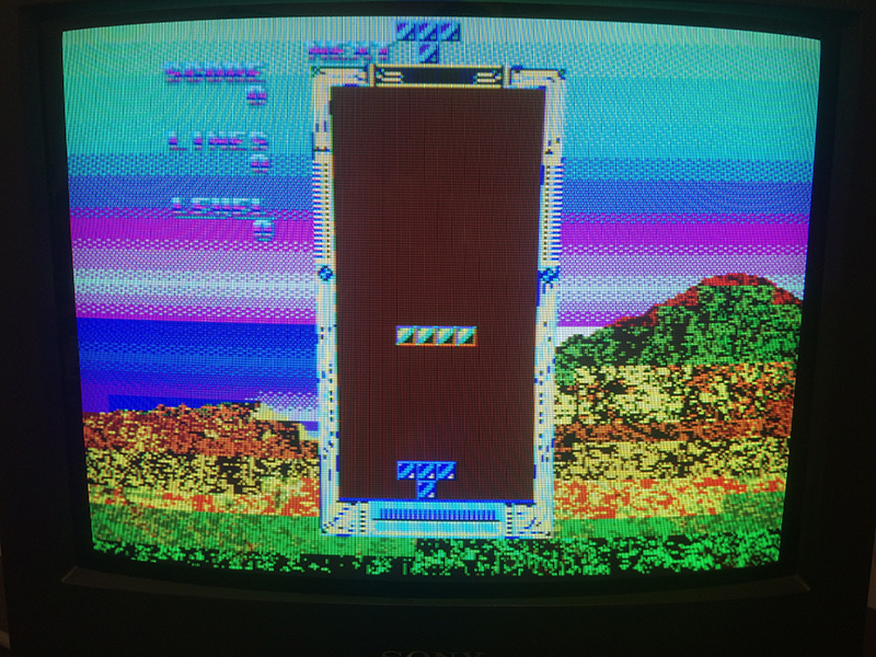
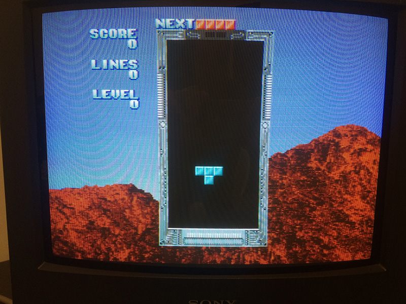
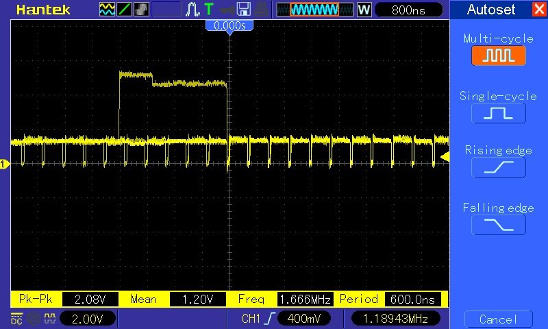
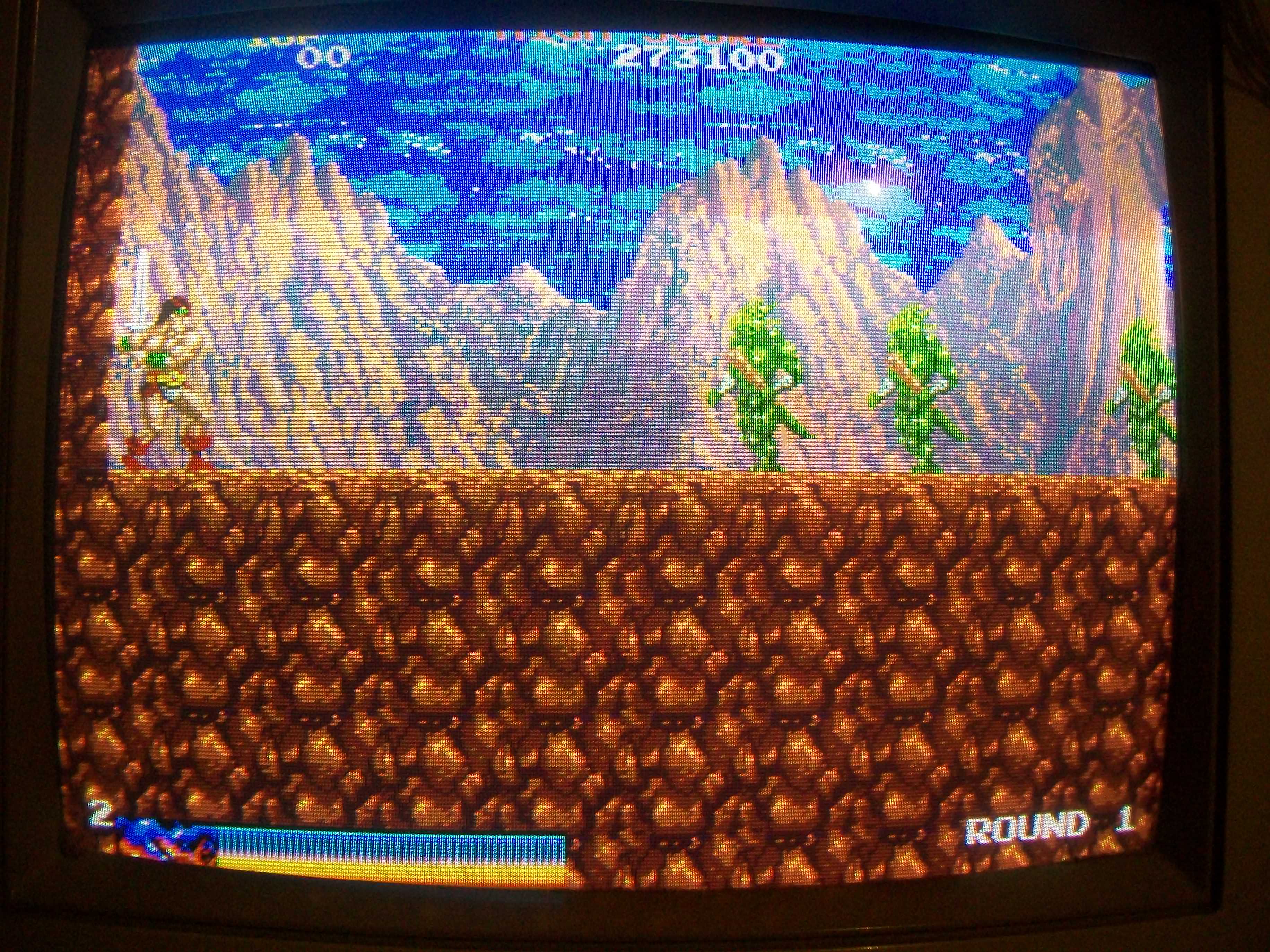
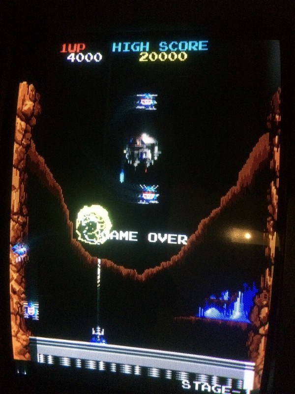
Game had this main fault:

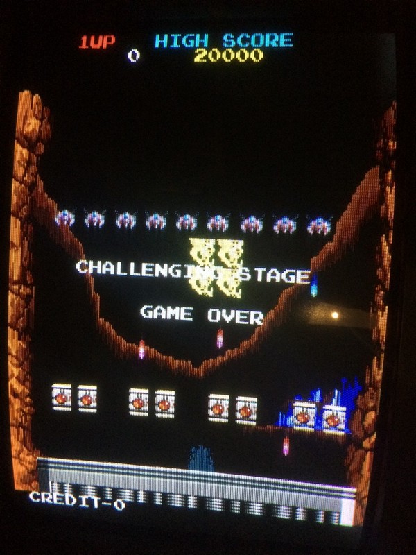
and even if it was not seen in the video of the seller, sometimes I got also the logo and some other images messed up


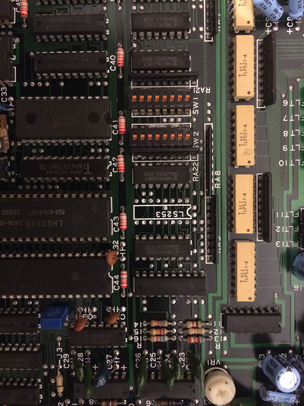
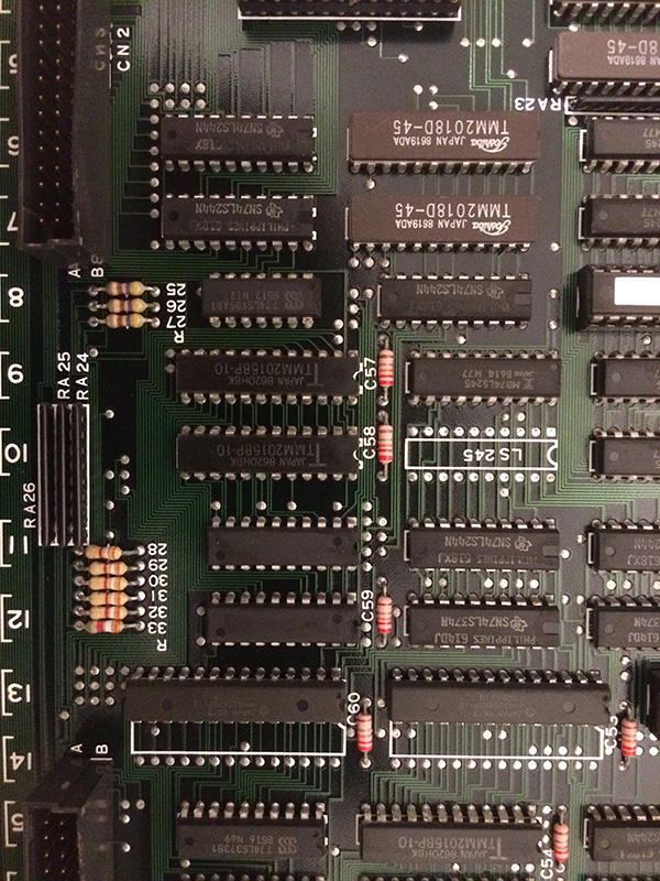
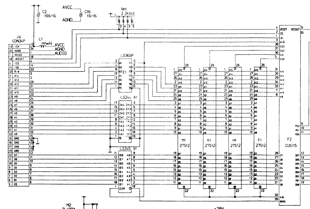
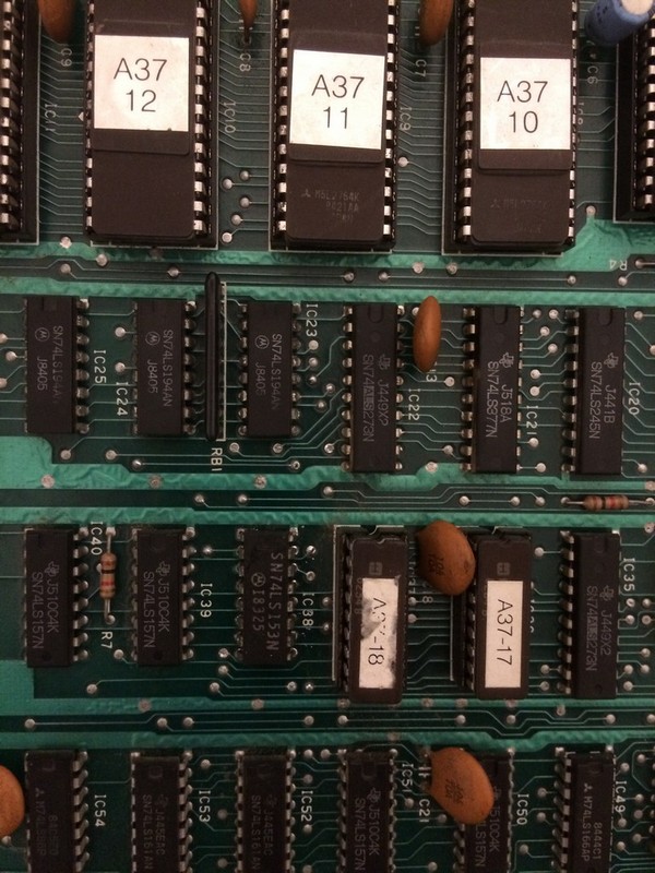
The sprite problem I was sure was caused by some wrong addressing of the sprite graphics, therefore I shorted some address line of the eproms on the video board to see which ones contained the sprite graphics and found the four responsible.

Addr 7 and 8 of the eproms 10 to 13 were fixed low. I traced back to a 74ls153@IC38  which had both outputs fixed .

Piggybacking it with a good one restored the sprites, therefore I proceeded with replacing it and fixed the sprite problem

The TTL was from Fairchild (not Fujitsu part!) and it was the oldest one on the pcb, dated 1979!

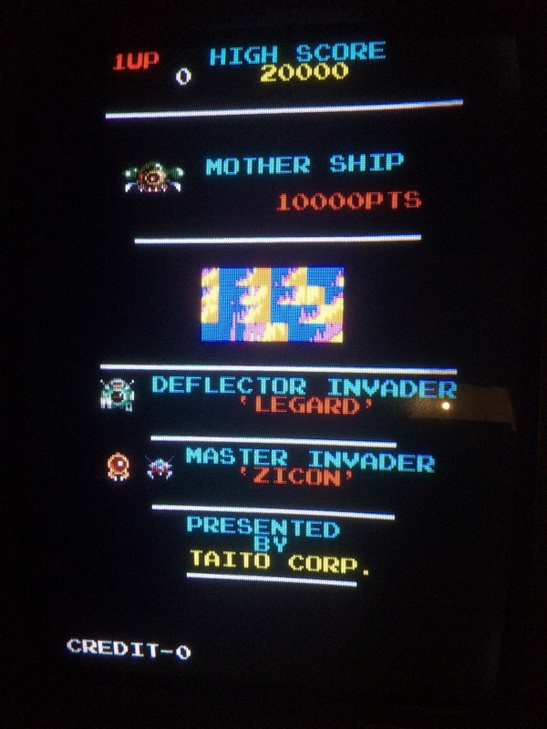
Now the logo problem, it was strange because sometimes it was shown right, sometimes bad.

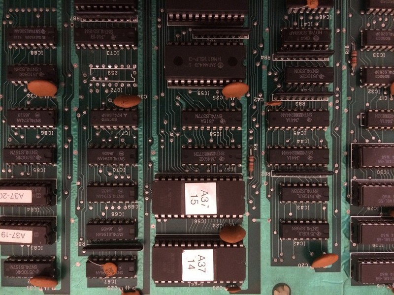
After some hours of playing, the logo was not shown right anymore, therefore I asked David Haywood (Haze of Mame fame) where it was contained and it pointed me in the eproms A14 and A15 (different bitplanes which were combined to form the final pic). Both eproms had to be addressed in the same time.

Also he told me that the graphic was bank switched, therefore some logic had to select a particular part of the memory area to show the correct gfx.

I probed their address lines and found the upper one A12, was always fixed low. I forced it high during gameplay and the backdround got corrupted but when the title was shown , the logo was there clear.

So the logo was contained on the upped half of the eproms and the logic was not selecting the A12 bit high or low depending on the situation.

I traced back to the only Fujitsu ttl present on the board, a 74LS259@IC72,  8 bit addressable latch.

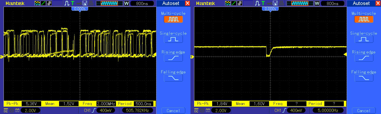
Before desoldering it, I tried to understand the datasheet of the part, which is not very common to see on arcade boards , and probes 3 select inputs which were oscillating and the enable line was pulsing everytime it changed from title logo to gameplay.

All his outputs were stuck low, and the HP logic comparator confirmed some outputs were at the wrong logic. Only few are used by the hardware, but I expect in later levels I could get other wrong graphics…

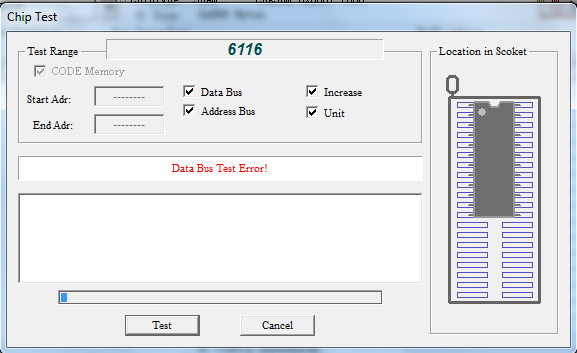
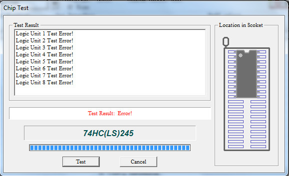
I desoldered it and tested out of circuit:

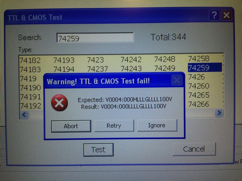
Turned out Fujitsu was again the source of problems!

I had a hard time to find a replacement, because as said the 74259 is very seldom used by arcade hardware.

At least I found one in the following junk pcbs I had: Rock and Rope boot, Equites and Dig Dug.

I took the one from the bootleg (it is always a pity to cannibalize an original board 🙂 ) and problem was fixed!


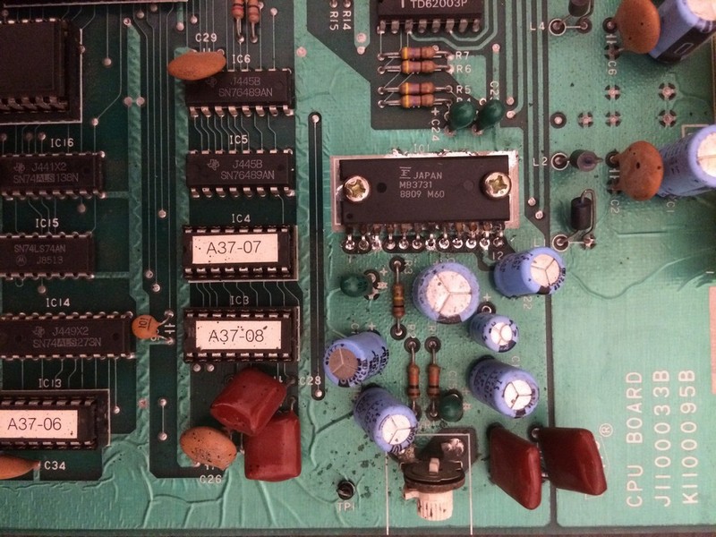
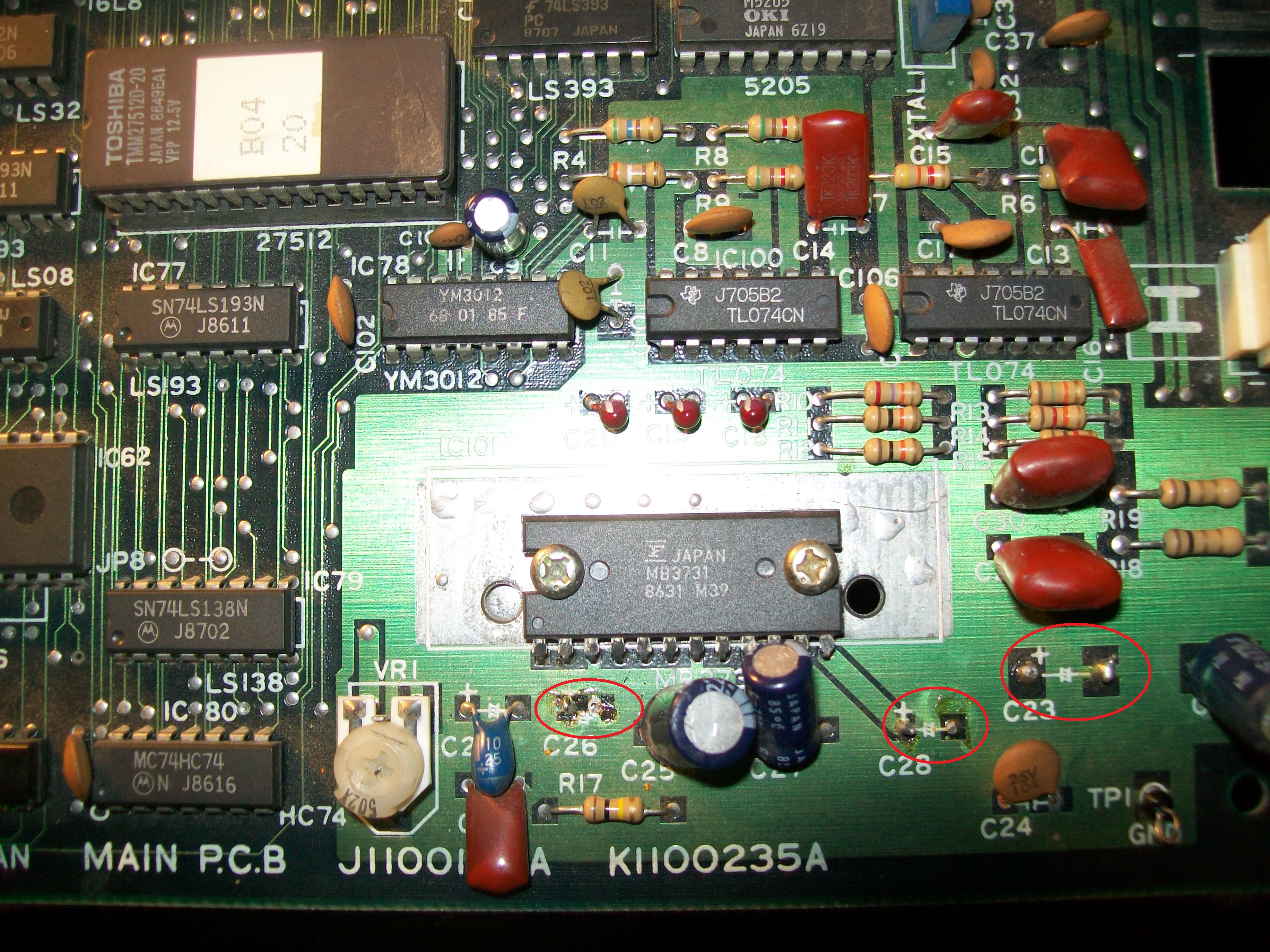
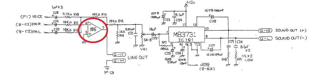
Since the pcb would go directly in my collection,  the last thing I wanted to fix, was the ugly hack they did by replacing the original amplifier with an LM380 (same used on 1978 space invaders….)


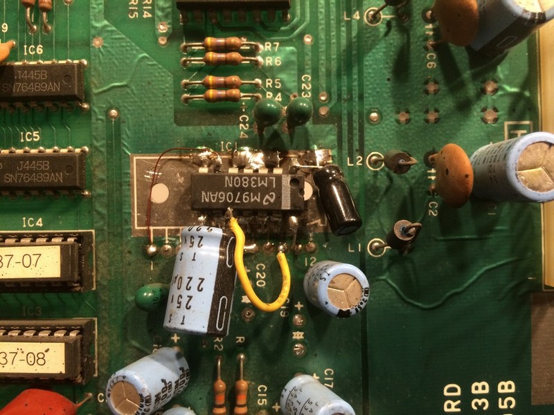
This thing worked but it was really ugly!

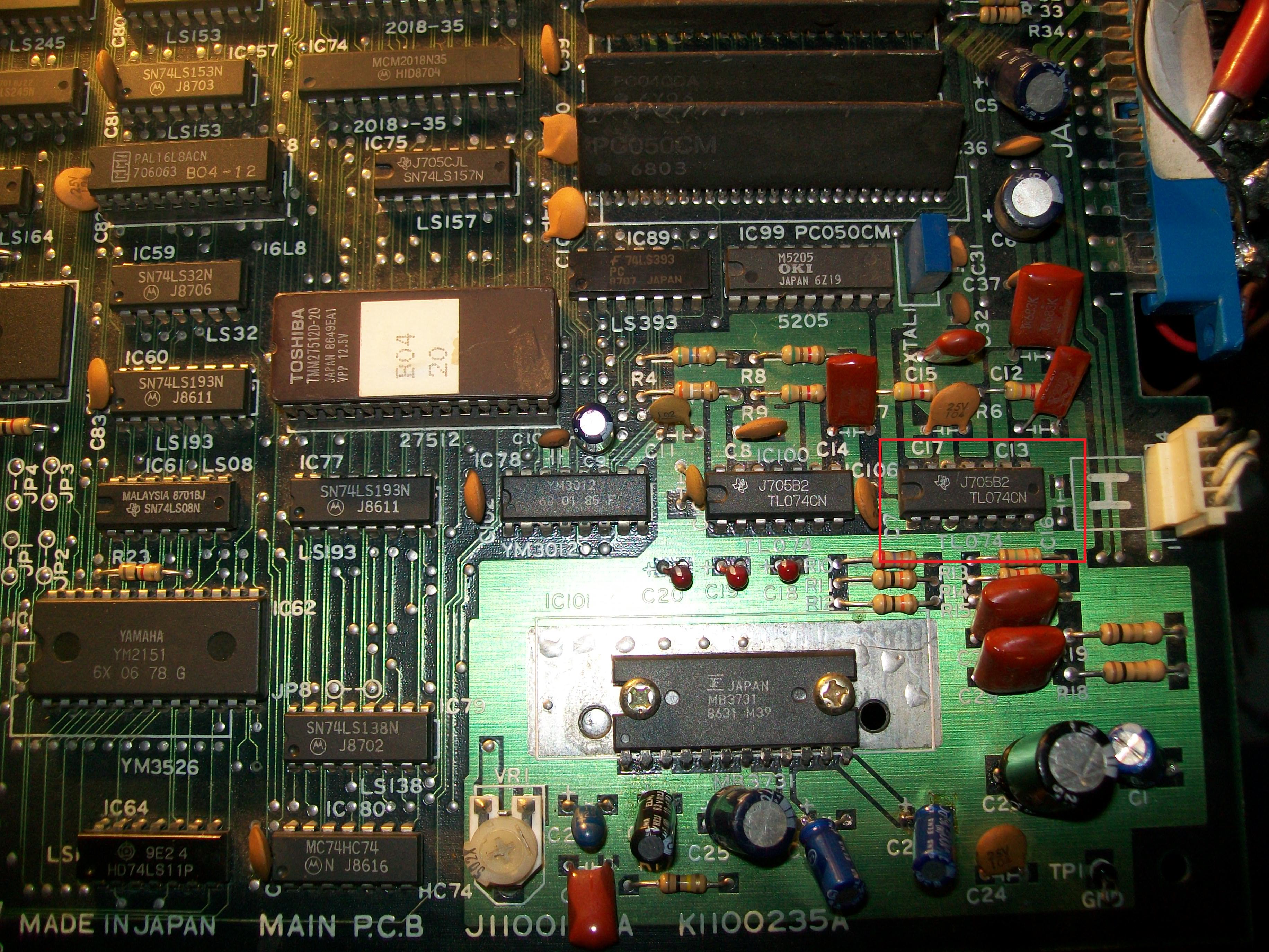
After spending one hour to clean the disaster with soldering irom and soldering wick, I installed back in place the 2x missing caps and I looked to find the original MB3731 amp among some of mine junk pcbs.

Besides being used on Taito hardware of the era, it was often used on Konami hardware from late 80s/early 90s.

I took it from a junk Main Events pcb and now it looks much better:


SEGA System 16 repair log #1

 PCB Repair Logs, Repair Logs  Comments Off on SEGA System 16 repair log #1
Feb 092017
 

My Alien Syndrome pcb one day decided to stop working and it showed a black screen.

I changed the battery 9 years ago and I thought it was suicided.

Just to be sure I tested it romboard and FD1094 module on another motherboard and it worked without problems.

I took a Tetris romboard then and tested on Alien Syndrome motherboard and this time the game showed a stuck reddish diagnostic screen which unfortunately I didn’t take a picture of.

Tested the inputs to see if there was a shorted one but there were all OK.

The program was running otherwise I wouldn’t get a stuck diagnostic screen therefore looking at the schematics I started to probe the 74LS253 (all Fujitsu parts) to see if the comunication with the cpu good.

The logic probe didn’t show stuck signals but I didn’t trust it and proceeded with piggybacking all of them with a good 253.

The game booted when I piggybacked the 74ls253@C15 but with wrong colours.

I desoldered it and tested it on my programmer and it was confirmed bad

After changing it I was welcomed with a running game but as said wrong colours

I ran the diagnostic memory test and the ram @J10 was given as bad.

Unluckily the ram was under the romboard therefore difficult to test in circuit

I decided to have another look at the schematics:

As you can see we have 2x 74ls244 which address both rams. The RAM given as bad was only J10 therefore it couldn’t be the 244.

After the 16 bits data lines we have 2x 74ls245 , and the first 8 bits from ram J10 are connected to the 74ls245 @H10.

Without even probing anything it was clear for me which chip to change blind

We had a Toshiba 2015 ram and a Fujitsu 74ls245.

Obiviously I decided to change the fujistu part

The guess was right because the game was fixed 100%


Shinobi repair log

 PCB Repair Logs  Comments Off on Shinobi repair log
Feb 092017
 

This pcb from my collection developed lately a sound problem only with the jump sound which is a sample


This particular sample was distorted, the others were all OK

The clock and the 7759 sound chip which is responsible for the samples I was sure they were OK otherwise

all the samples would have the issues

I dumped the sound program rom 11372 and the samples roms 11288 and 11289 expecting that one of them could be corrupted

but surprisingly everything was fine.

If you have noticed, I still the original NEC module with a suicide battery from 1987. The battery is still working after all these years but unfortunately cannot be changed since the module is one piece injected with epoxy.

I started to think that the module could have the decryption key stored in ram somewhat corrupted after all these years and this could affect of course the sounds

Therefore I proceeded to use a z80 with the decrypted program rom taken from a mame set which use the same 5358 rom board (it is currently set 5)

The jump sound was correct with decrypted rom, confirming my theory that the key in the module is corrupted.

Rastan repair log #4

 PCB Repair Logs  Comments Off on Rastan repair log #4
Feb 082017
 

I had on the bench this Rastan PCB:

Board suffered from severe graphical issues, sprites were absent and jailbars all over the screen.Sound was corrupted too:

I had the feeling that the backgrounds were actually good although the jailbars since the lines were changing as sprites moved so I went to check this part of circuit.Objects are generated by the custom ‘PC090’  which takes data from some 1Mbit MASK ROM and write them to four 2018 static RAMs:

Probing the four RAM revelead weak signals on data lines of the one @IC5:

Piggybacking a good RAM restored all graphics:

The chip failed when tested out of circuit:

But after I installed a new RAM on board, sprites were not good as when I made piggybacking, just blank with no colors :

Probing around I found a 74LS245 @IC85 which didn’t do its job :

This is used to exchange data between two bus called ‘IO BUS’ and ‘MD BUS’ on schematics:

Chip failed the out-of-circuit test:

Graphics were OK now so I moved on to trobleshoot the sound issue.I found three missing electrolytic capacitors in sound section : @C23 (1000uF 16V), C26 (10uF 16V), C28 (100uF 16V):

and replaced a bad one with increased ESR @C27 (100uF 16V) :

But this was not enough to restore a good sound.So I decided to use my new audio probe:

An audio probe is essentially a portable amplifier useful to test parts of an analog sound circuit by ‘hearing’ them and hence figure out what is actually faulty.Mine was designed by Phil Murr from UKVAC forums, credits to him:

https://www.ukvac.com/forum/topic355350.html

Using it revealed that sound was still good on input pin 6 of the TL074 OP-AMP @IC106 (used on final stage to mix FM music with PCM samples) but then was outputted distorted from pin 7 :

Replacing the OP-AMP cured the issue.Mission accomplished.


 Posted by at 11:21 pm

Rolling Thunder repair log #2

 PCB Repair Logs, Repair Logs  Comments Off on Rolling Thunder repair log #2
Feb 042017
 

While I was playing this game from my collection  ,I discovered it was missing all the samples (gun shots, walk and so on).

The game is a Namco system86 with an additional daughter board used for the samples

Before beginning the troubleshooting I searched on Internet for a similar problem and found a repair log

where all the caps on the daughter board weere changed , restoring the samples.

I am not a fan of changing caps randomly so thanks to Atari I checked the schematics and

found that the on the daughterboard there is a little circuit which produce 24V out of the 5V for the op amp.

Around that circuit there was a hissing noise therfore I checked if the 24 volts were present which was confirmed.

I proceeded with my sound probe to see if from the op amp I could hear the samples but when I turned on the game,

it continued to reset itself….the watchdog was active.

At this point I was a little puzzled and tried to disconnect the daughterboard which granted me with the game that booted

but with missing background and crashed as soon as the attract mode began.

I took some customs from various Namco games and checked if the game booted but no luck.

Also I hadn’t another Rolling Thunder to check the two customs on the daughter board therefore I put the pcb apart for sometime.

After some weeks i resumed the pcb and without much hope I checked various TTLs until I found a 74LS244@A1 on the daughterboard

which had pin 12 not oscillating properly while the input was healthy (Fujistu part….)


I piggybacked it with a good one and the game booted briefly correctly.

After changing it, I returned to the original state with the gameplay without samples.

I tested the output of the op amp TL074 with the sound probe and I could hear the samples.

Ttherefore there could only be one cause which was the capacitor @C1 placed between the output and the daughterboard connector, which infact was tested as open with an ESR meter

Changing it restored all the samples.