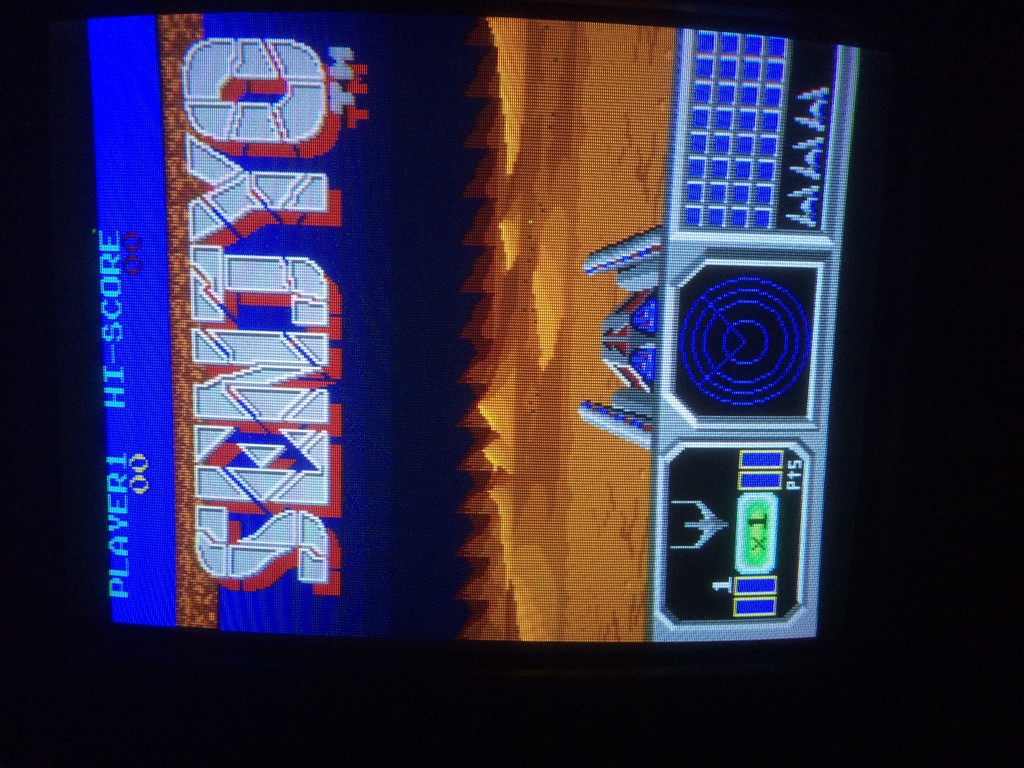
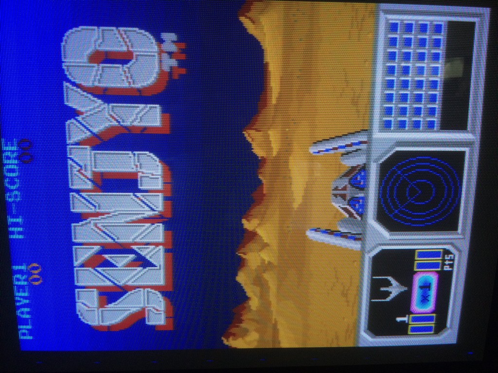
I bought this game declared 100% working for my collection but as soon as I fired it up I noticed something strange:
One of the mountain layer looked very strange and there was also some stripes of mountains in the sky
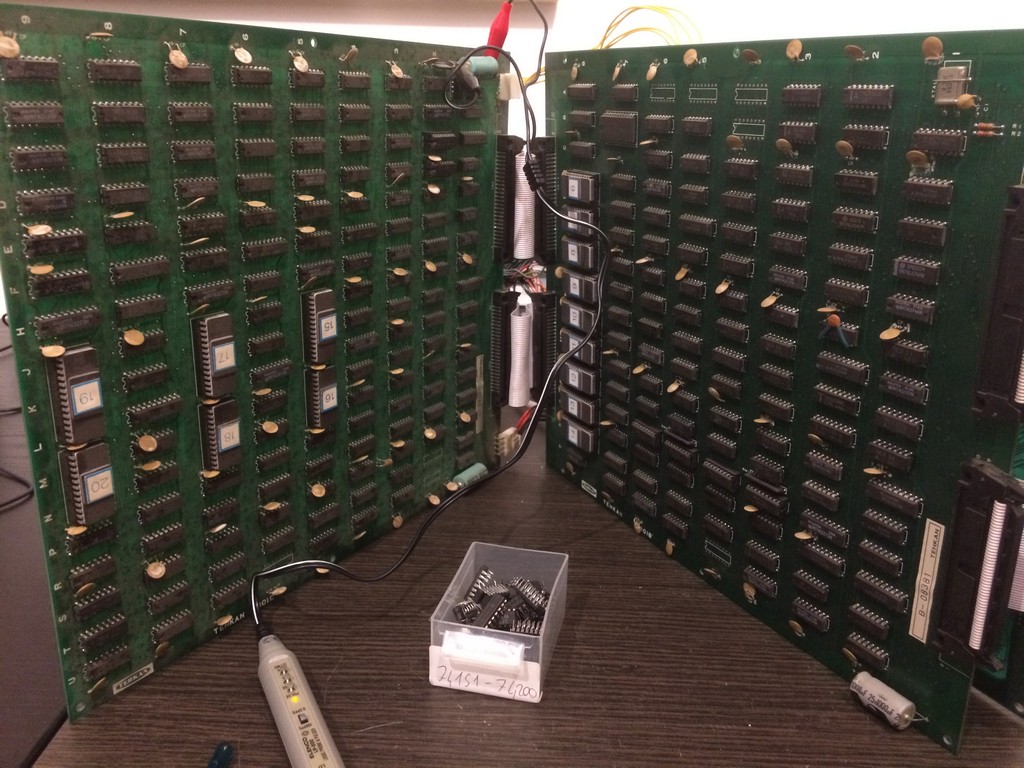
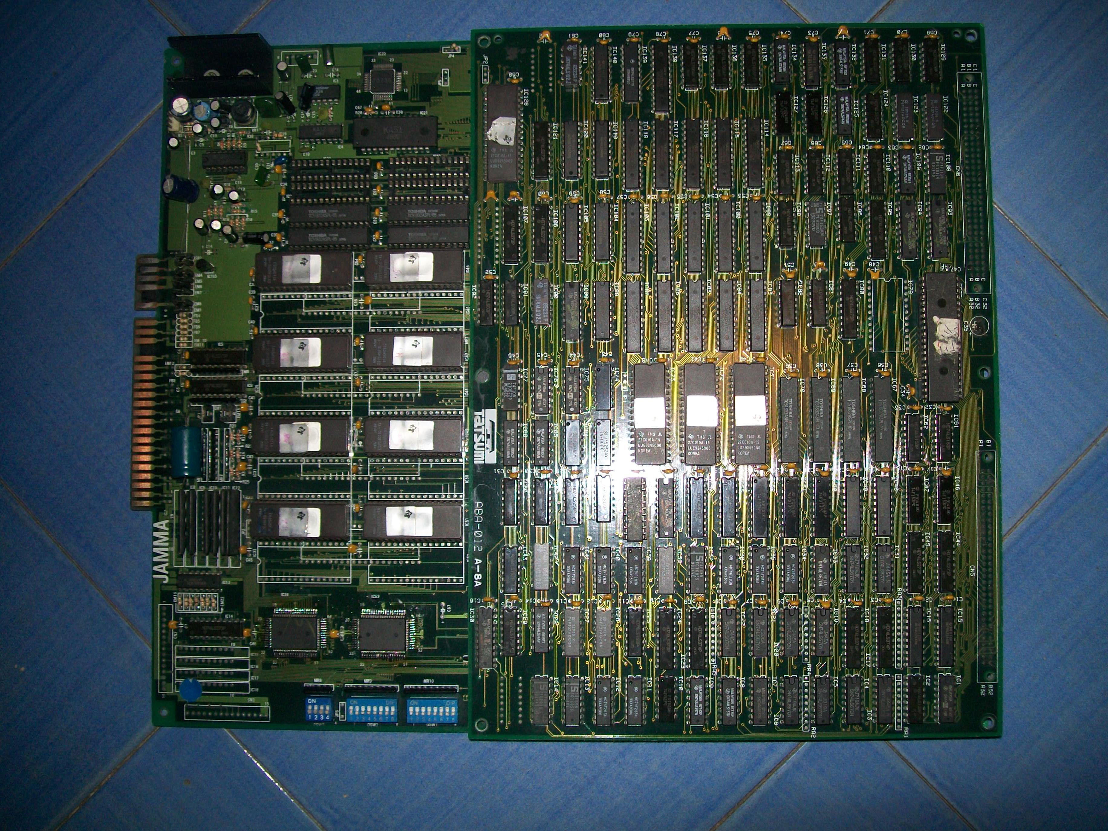
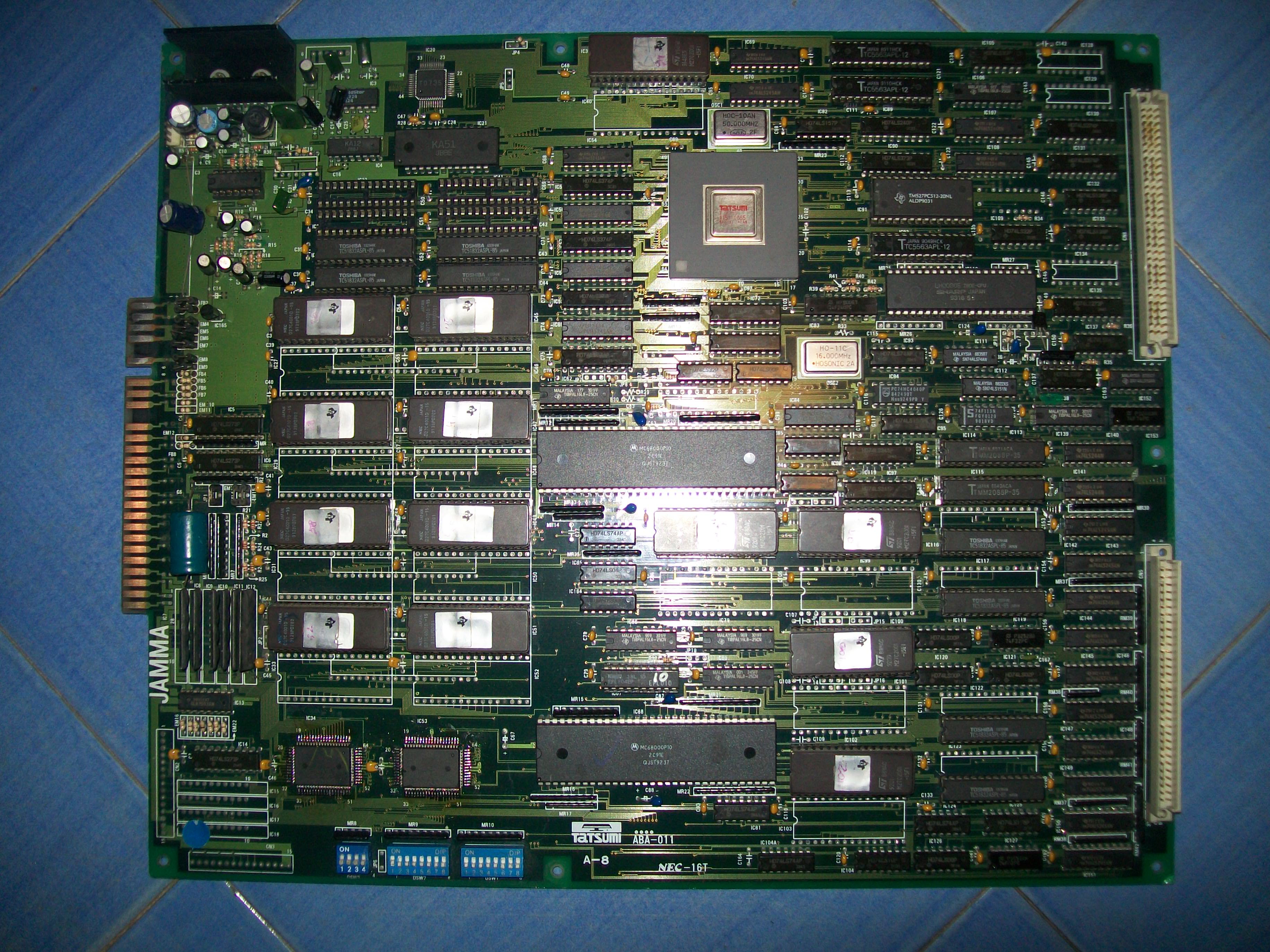
This game has no schematics and it is a particular complex and populated hardware with lots of TTLS and rams.
The game is on a 3 layers pcb so I had to find a way to test the components in a confortable way:
The upper board with the connector has the cpu and sound section, therefore I started to test the bottom pcbs and by shorting some signals I finally found the circuit dedicated to the last parallax layer which is near eproms 19 and 20.
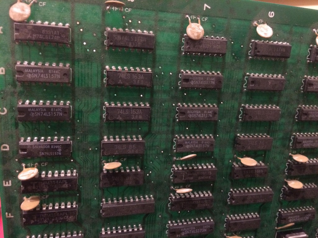
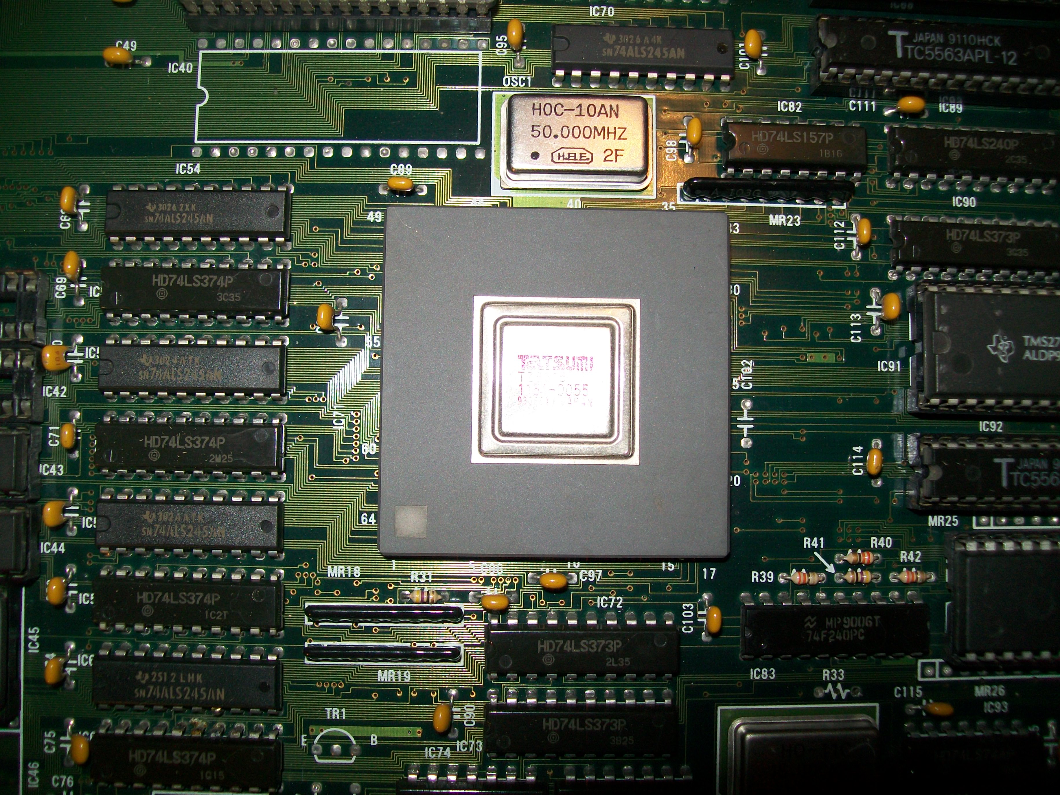
All the signals looked good but the 2114 srams has some dead signals coming to 4 addresses.
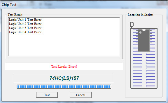
Tracing back I found a Texas instruments TTL 74ls157@9C whose outputs were all totally dead
Changing it fixed completely the background layer:
PCB Repair LogsComments Off on Big Fight – Big Trouble In The Atlantic Ocean repair log
Mar162017
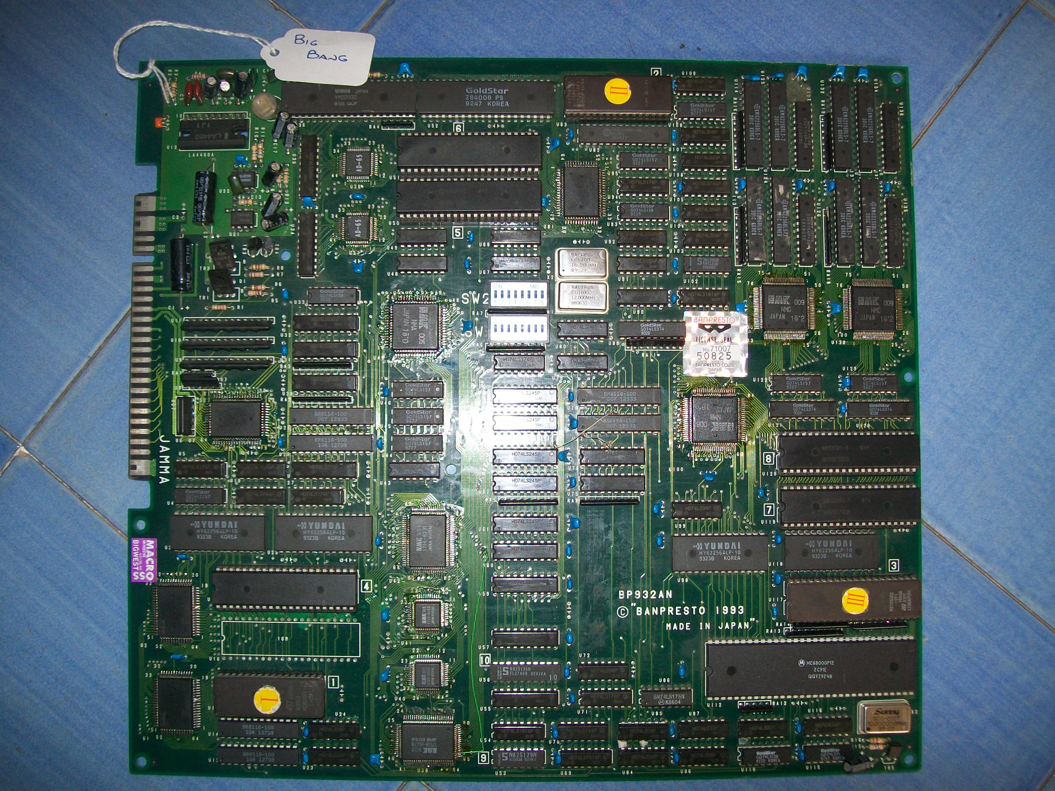
Got this rare Big Fight – Big Trouble In The Atlantic Ocean (this is the full title) PCB for a repair :
For the uninitiated game a beat ’em up which resembls Final Fight but it features also a versus mode.It was developed and published by the obscure Tatsumi manufacturer in 1992, it was one of their last arcade game before focusing on novelty sticker printing business.
The board was completely dead, I got only a black screen.The hardware is complex : two 68000 CPU, a large PGA sprites custom IC, many PLDs, lots of RAMs.Here is picture with the daughterboard removed:
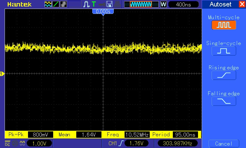
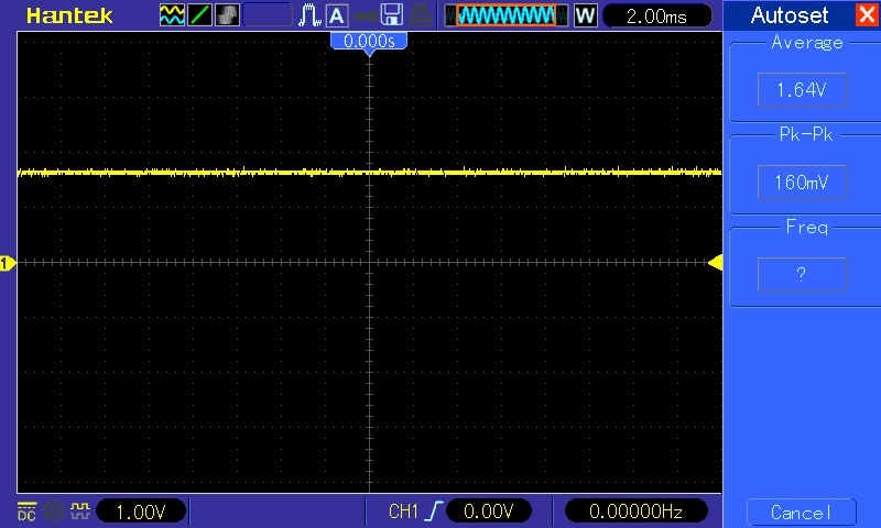
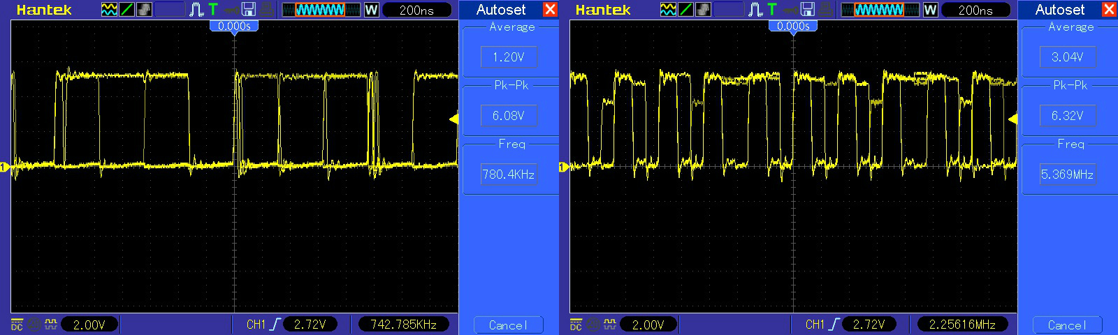
Probing the two 68000 revealed no clock, master clock is generated by a 50MHz oscillator and then divided by 4 in order to route a signal of 12MHz to both CPUs:
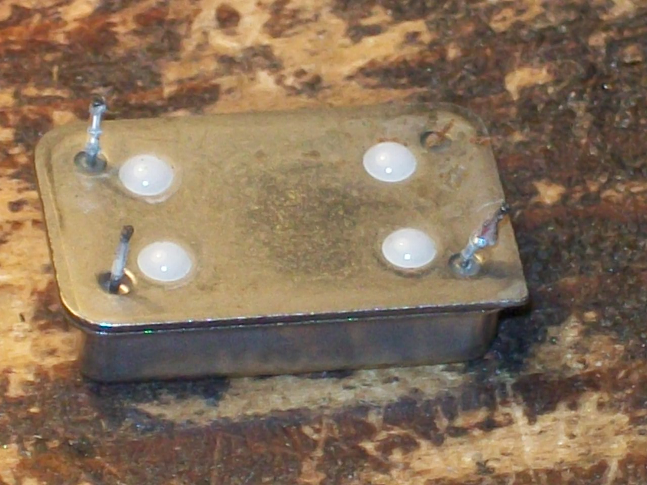
The output of the oscillator was dead, stuck at 1.64V :
I removed it and the its VCC pin was stuck on PCB detached from the package due rust corrosion:
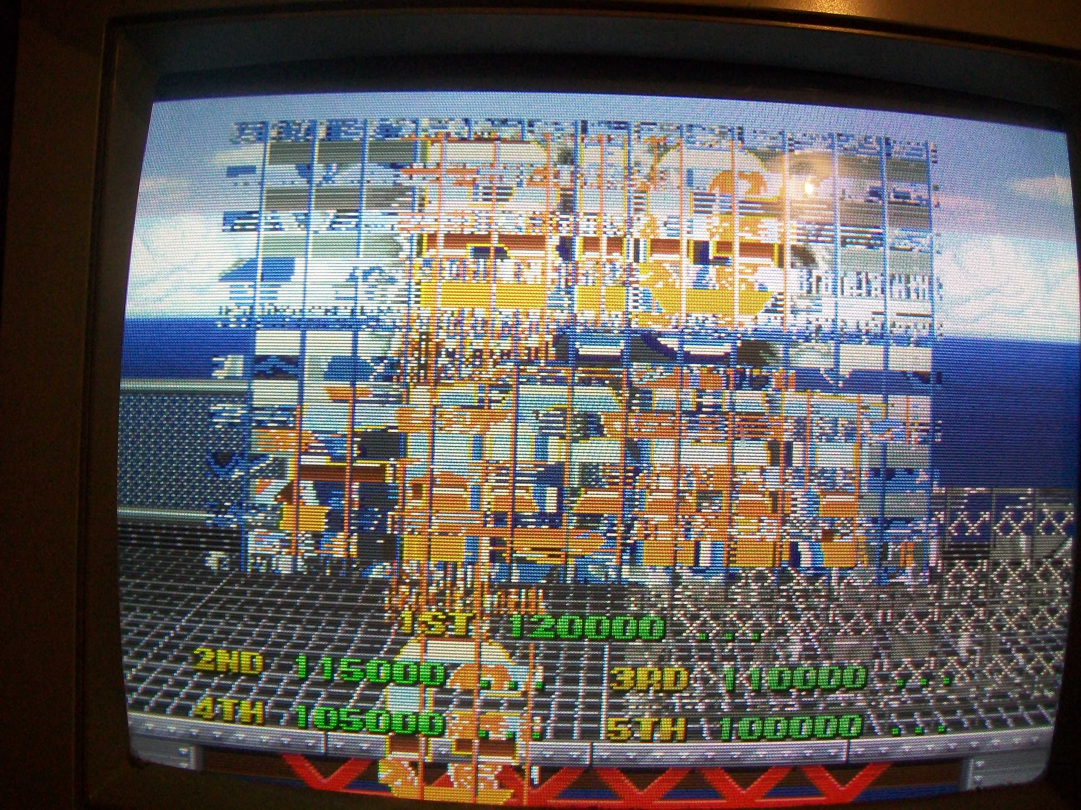
Fitted a good oscillator and board sprang to life although with bad graphics:
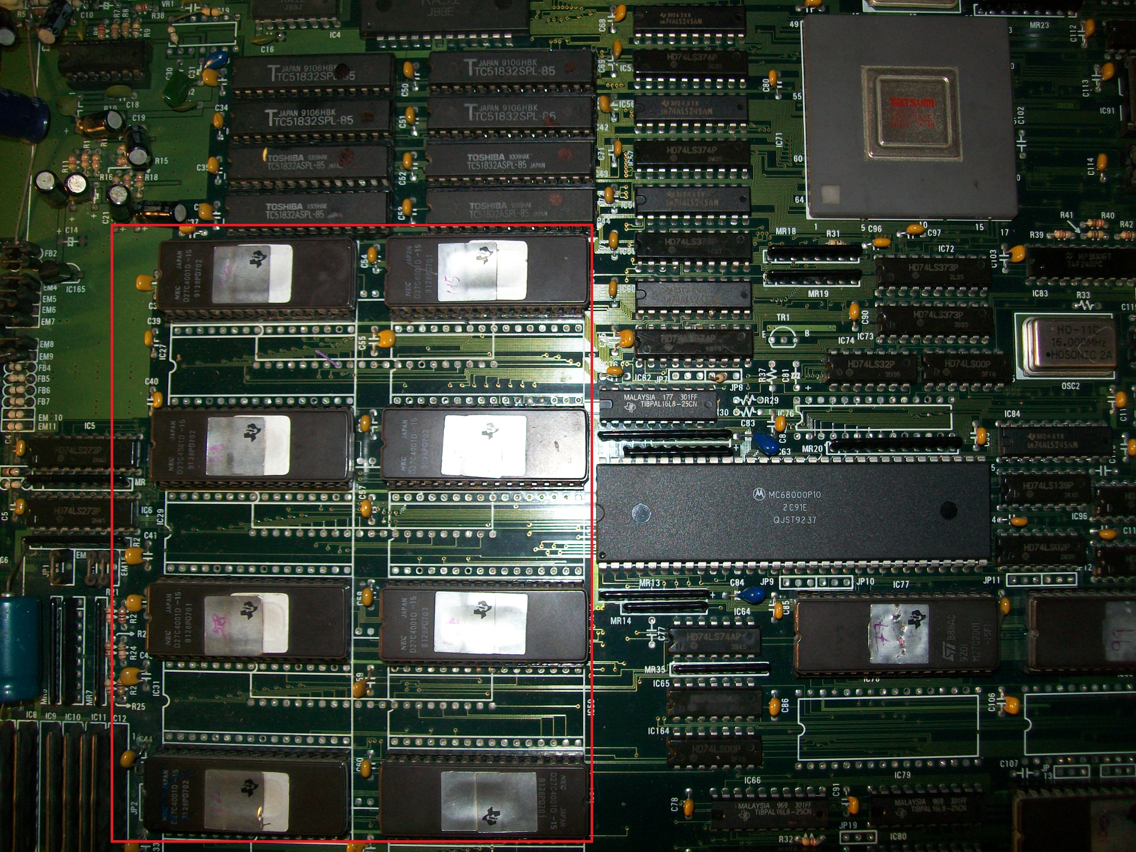
Doing a visual inspection I found four empy sockets, according to the MAME source PCB layout and pictures on the Net they had to accomodate four TC51832 32K x 8-bit pseudo-static RAMs besides the other four present:
Once fitted the four missing RAMs most of graphics were correctly displayed but sprites were absent :
The sprites are generated by the PGA custom ‘TZB315’ (see picture above) so I went to probe the surrounding area and found discrepancies between inputs and outputs of some 74ALS245 which are in the middle of ROMs and custom data bus:
I replaced them and, although they resulted good when tested out-of-circuit, I got sprites back although scrambled :
Sprites data are stored in eight 4Mbit 32 pin EPROMs:
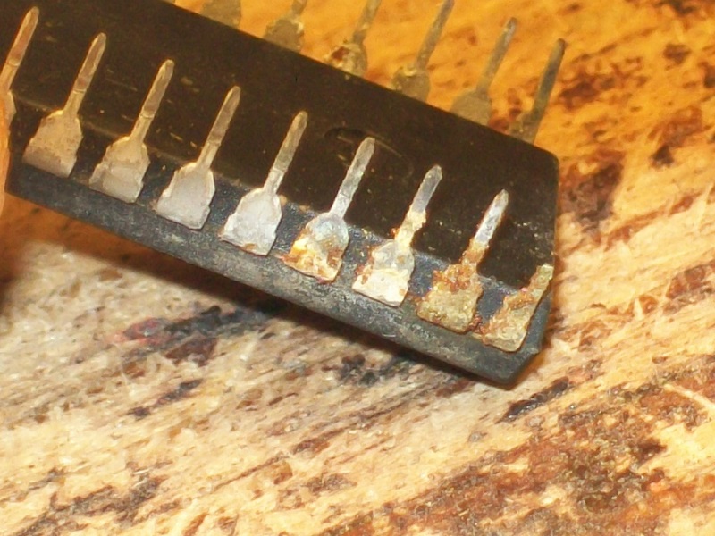
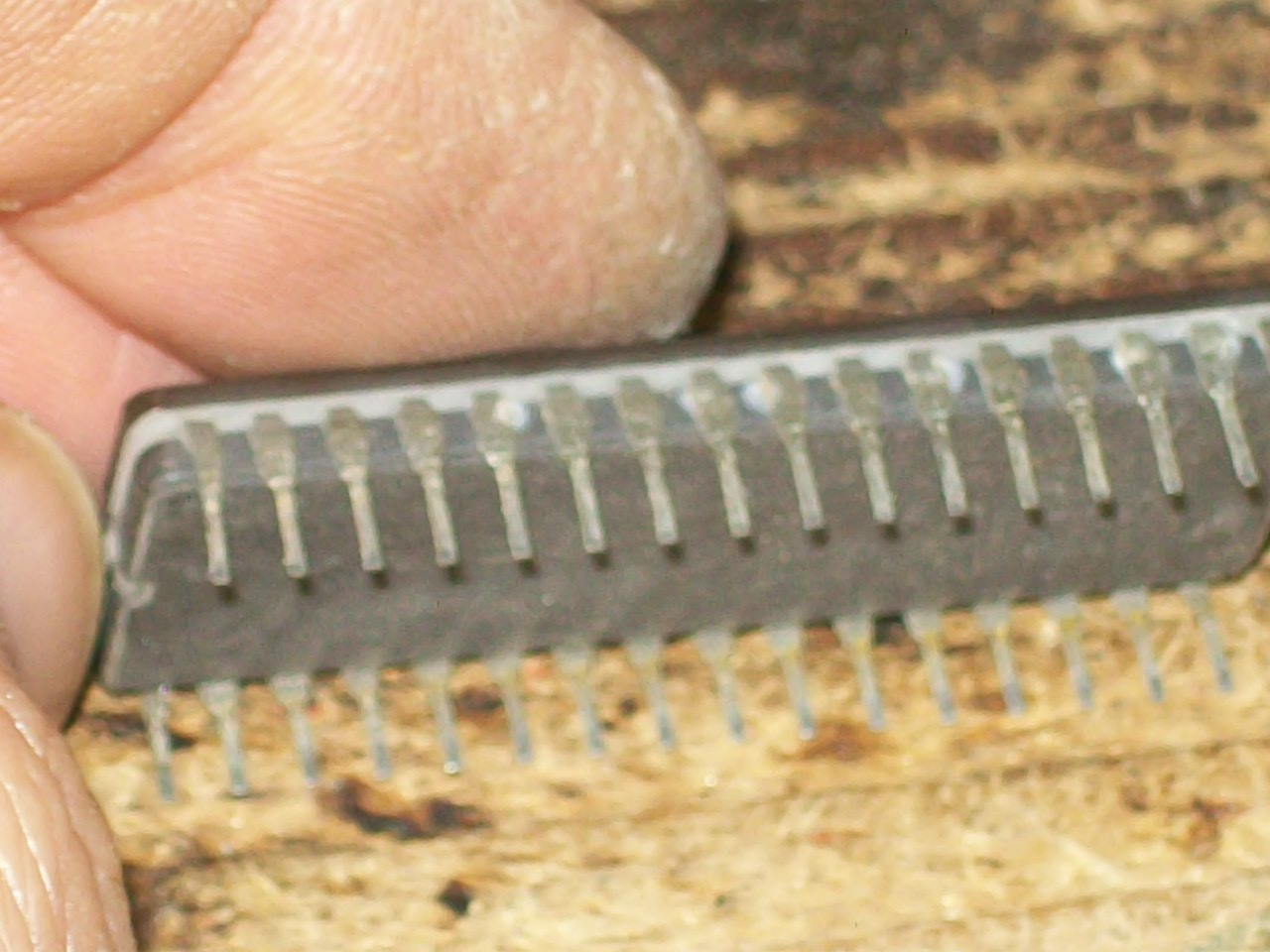
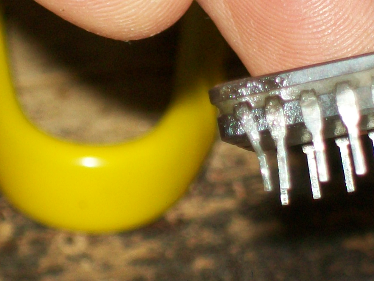
I dumped them and they matched the MAME ROM set but I noticed some of them had oxidized legs:
I cleaned them and at same time replaced a device with a dodgy pin:
This fully restored sprites:
But as you can see (or better, hear..) in the above video, sound was sometimes noisy and some voice samples were missing (like helicopter when you start a game or voice of special moves and enemies).
Here a recording from a working PCB for comparison:
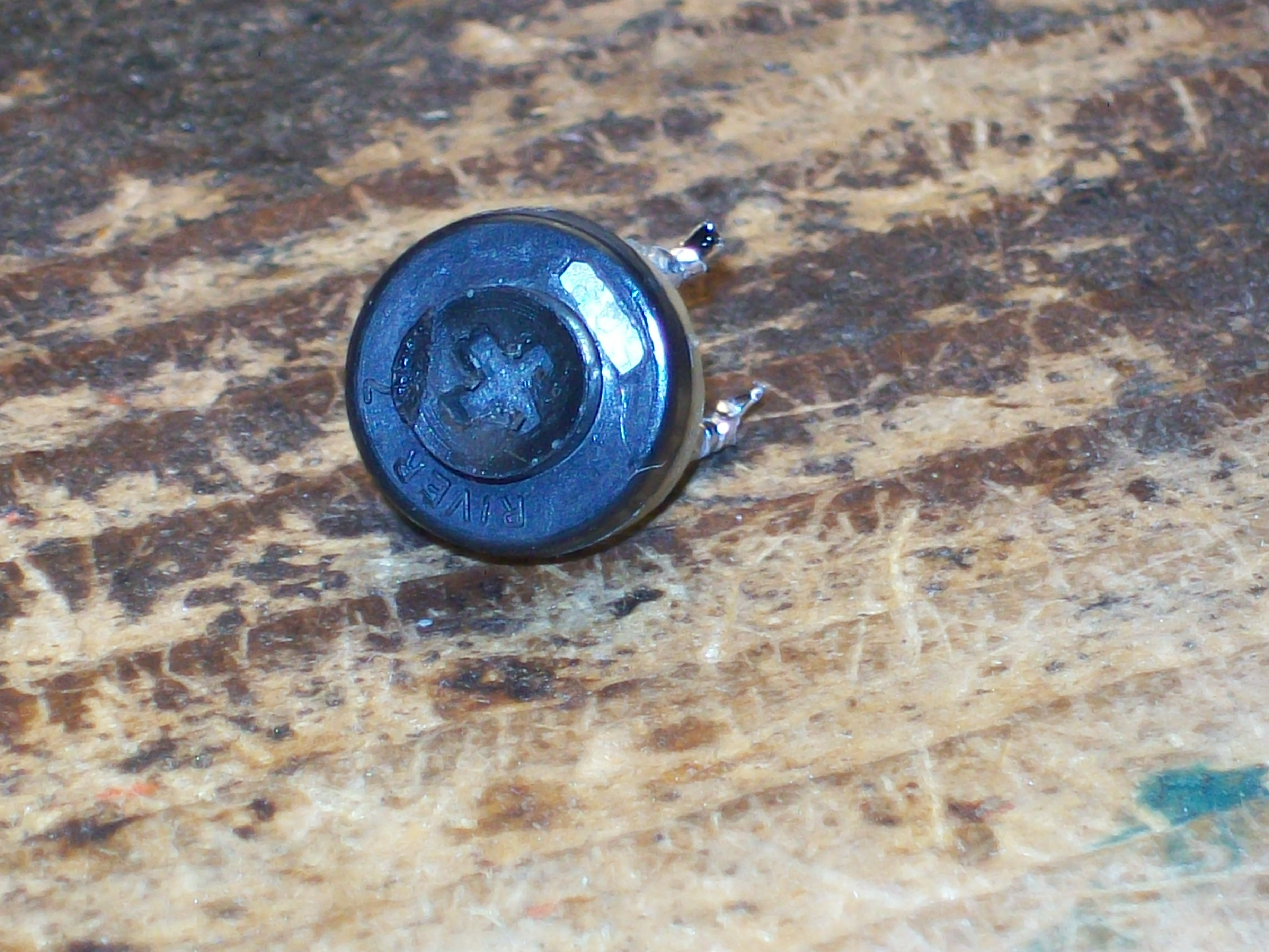
The background noise was due a dirty 50KOhm potentiometer, I removed and sprayed it with a contact claner :
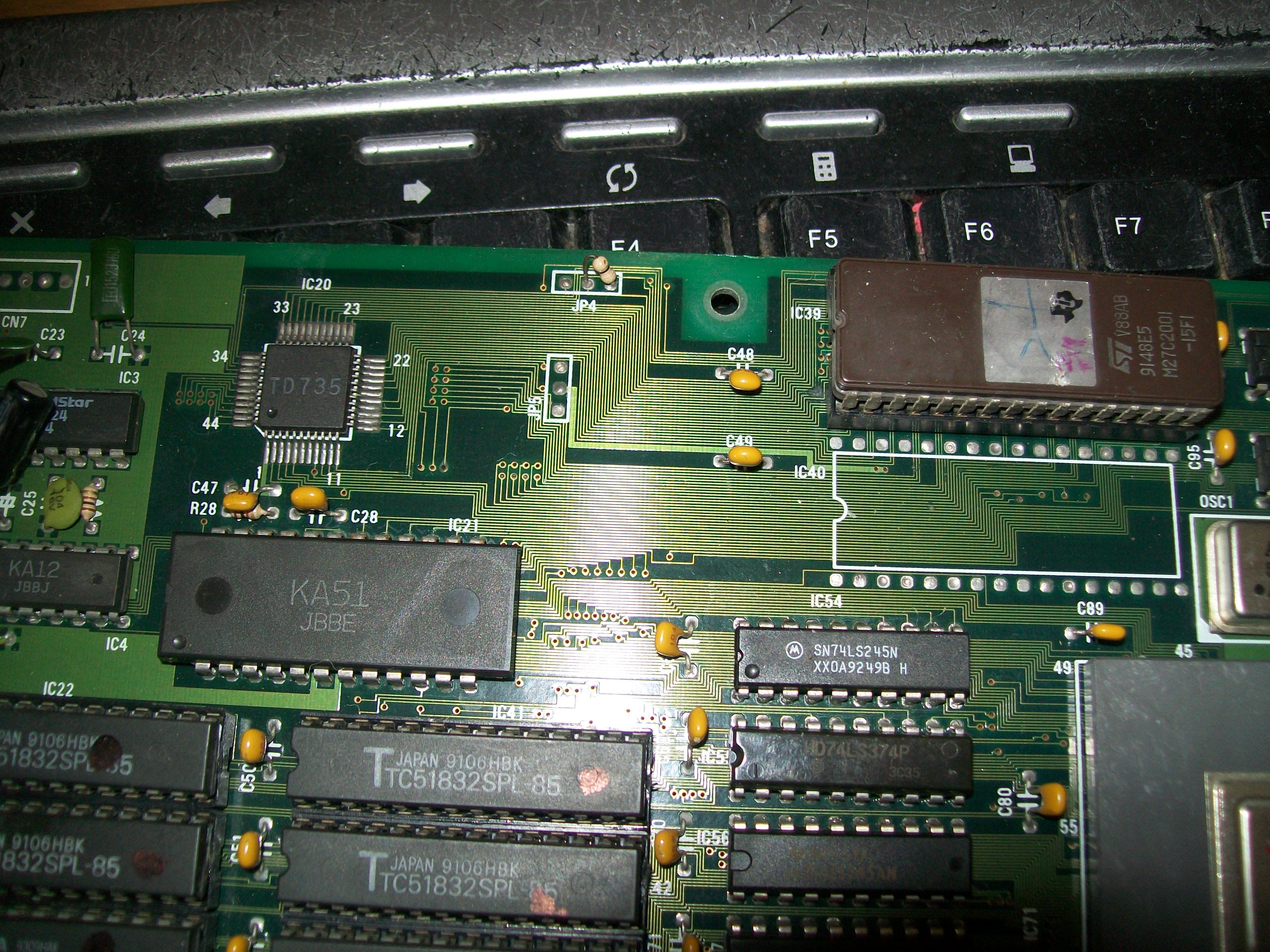
Voice data are stored in a 2Mbit EPROM and played by an OKI MSM6295 (corean rebadged one on this PCB)
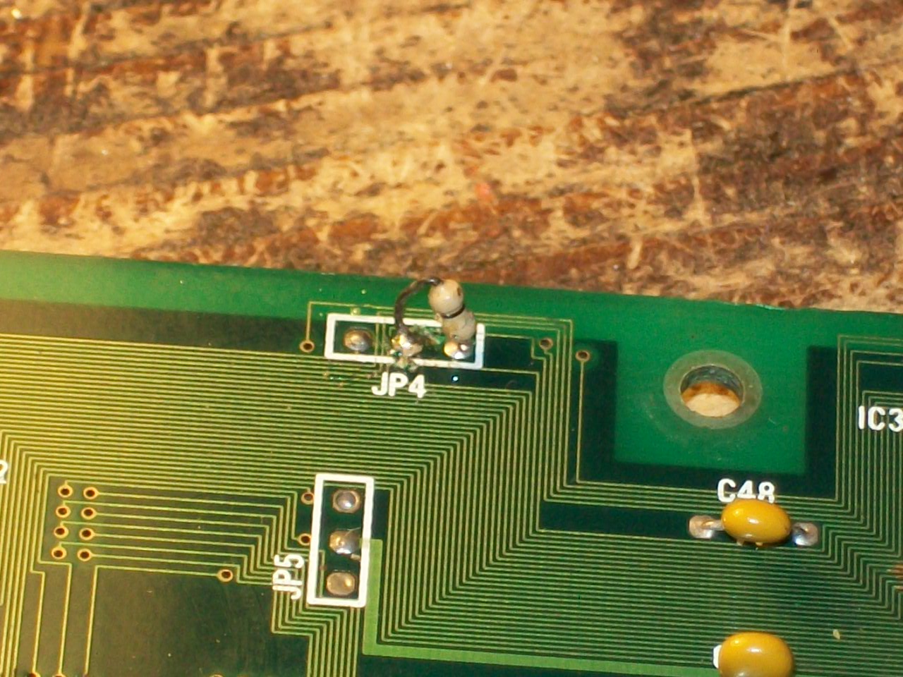
The dump of the EPROM was good, I also replaced the OKI with no luck.Probing the EPROM revealed that pin 30 (address line A17) was always LOW so the second half of the voice data could be not accessed.Doing a check with my multimeter revealed thas this pin was tied to pin 22 (/CE), this obvioulsy sounded me weird.Near the EPROM there was a jumper installed @JP4:
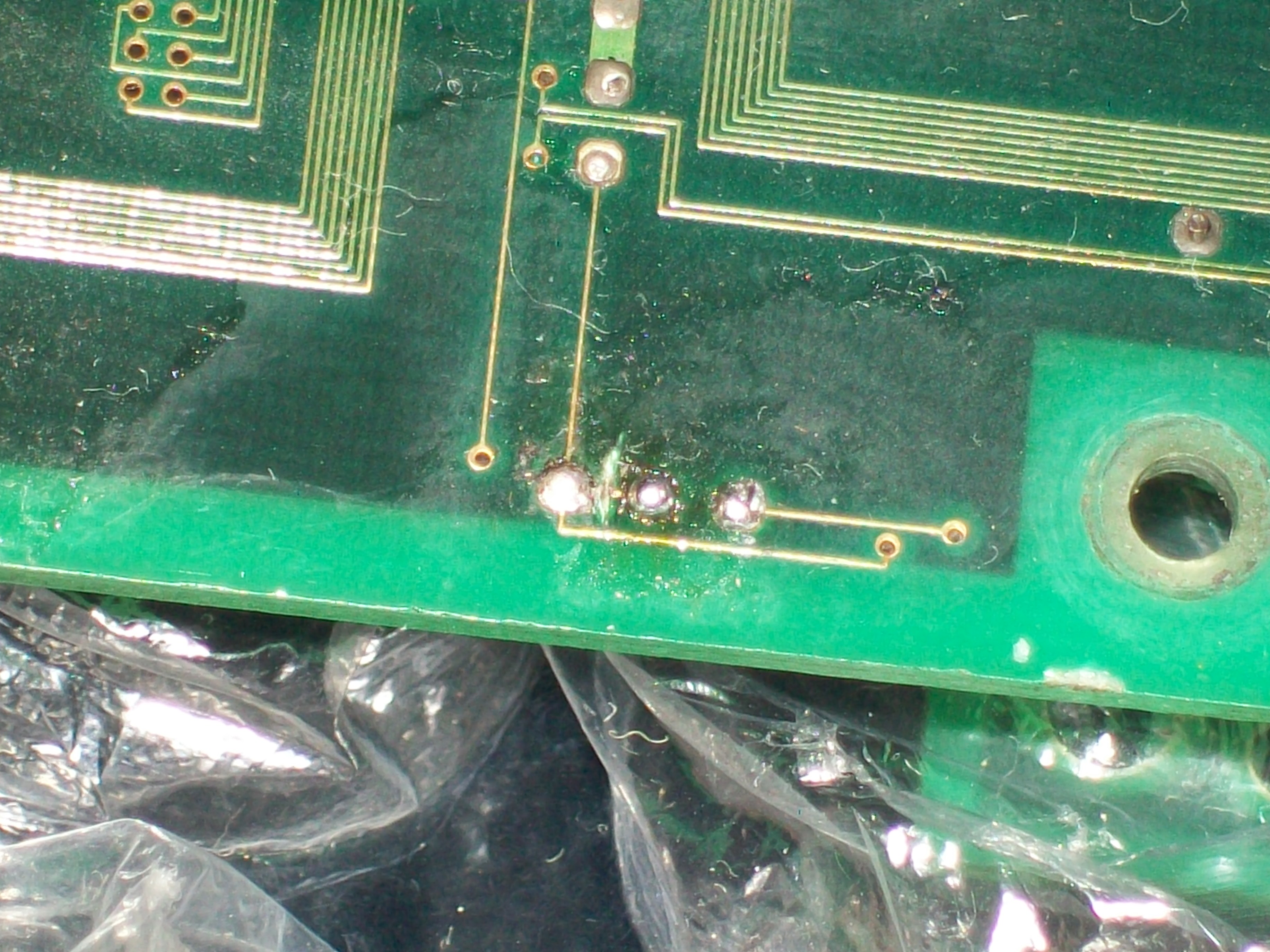
Looking at PCB pictures on the net I had confirm that the jumper had to be set in this configuration.But looking at its solderside I noticed a trace which connected the central pad to the left one.This obviously, along with the jumper installed in that position, caused the short between the left and right pad resulting the two signals being tied together.So, I cutted this trace:
This restored the missing voice samples.No further issues were found so board 100% working.
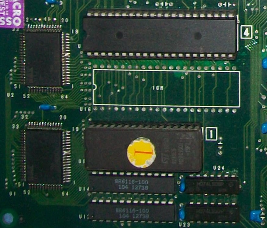
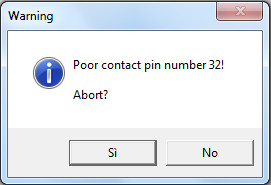
My programmer warned me about a bad contact of pin 32 (VCC) when dumping the EPROM labeled ‘1’ U15 which store foreground data, most likely the +5V wire bond was detached from package:
:
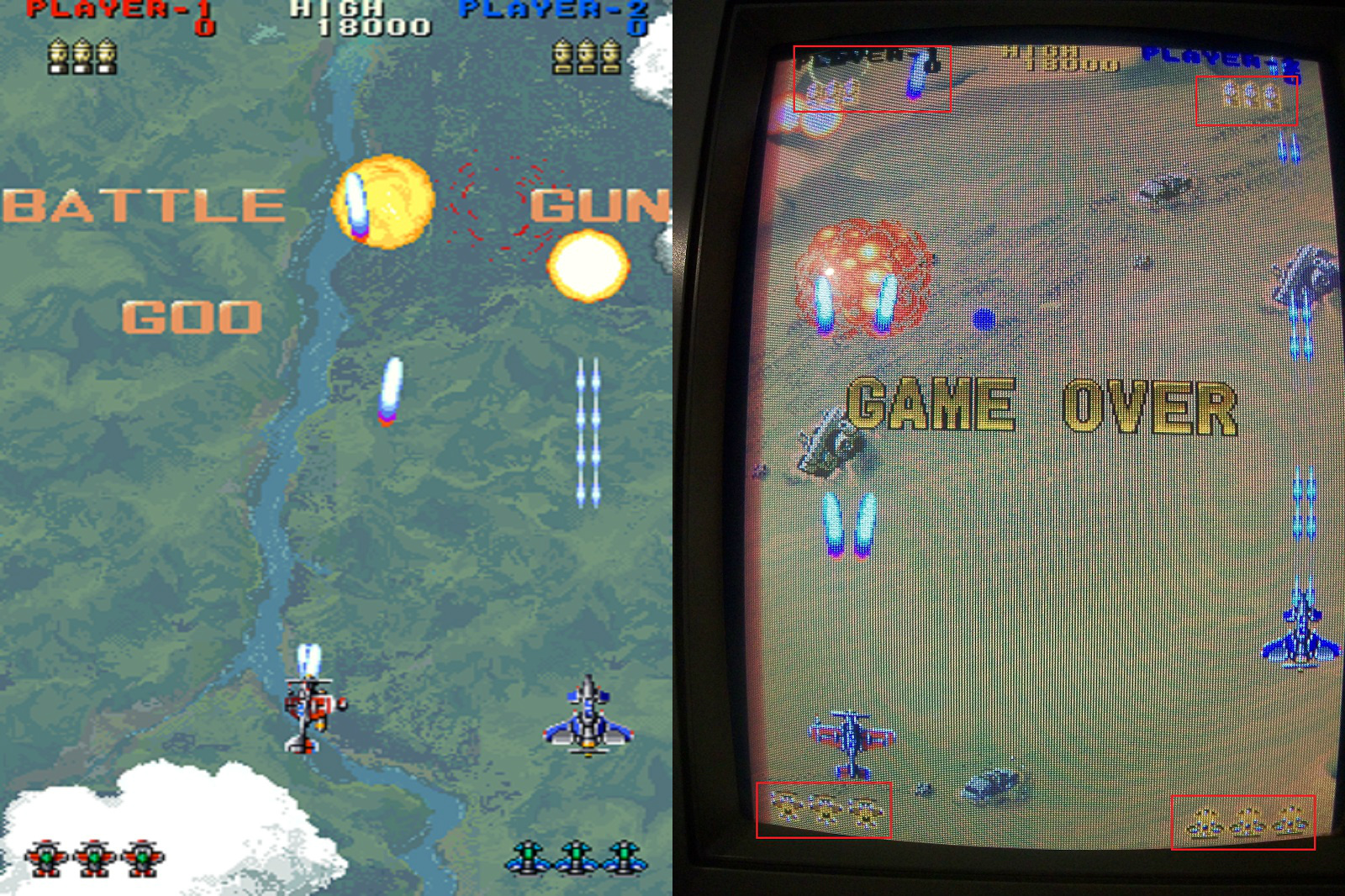
Replacing the bad device with a programmed 1Mbit EPROM restored all graphics but some garbage were present on screen:
I promptly fixed this issue reflowing some of the surface mounted ASICs.At this point graphics were almost good except for some foreground objects which had wrong colors (bleeding too in some parts).Here is a comparison with MAME snapshot on the left:
and in details some of the affected objects (MAME snap always on the left):
At this point I spent some time to understand how hardware works but, honestly, due total lack of documentation, it was a trial and error.I replaced some of the surface mounted customs until I caught the culprit :
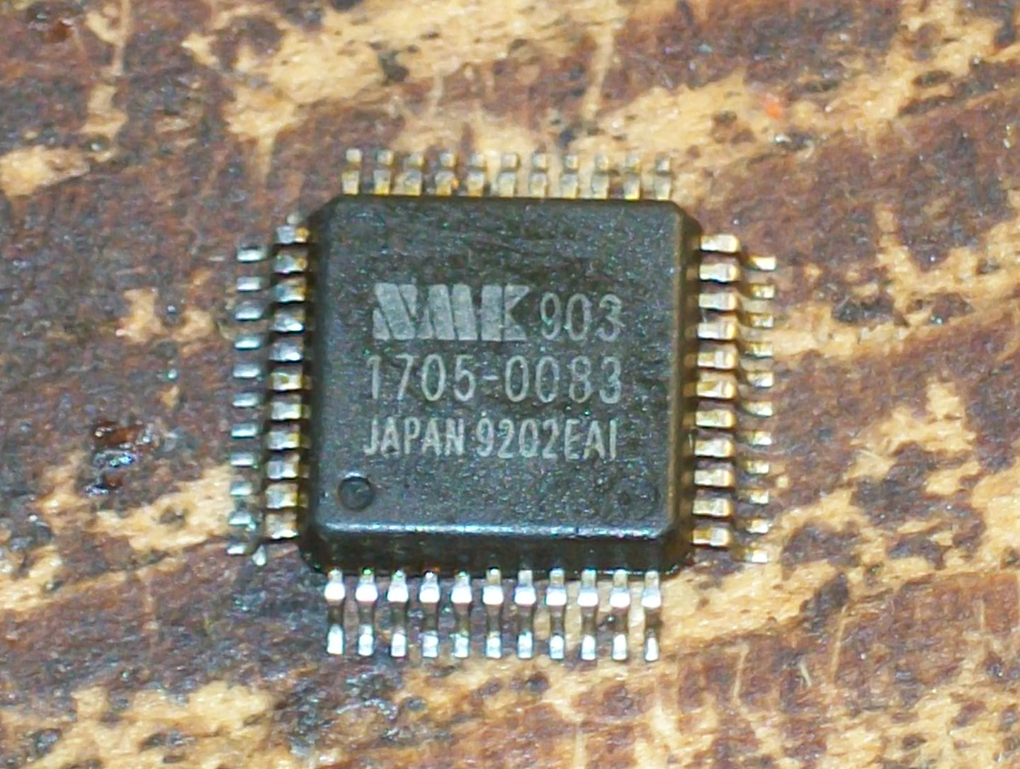
Replacing it (spare part was taken from a dead Hacha Mecha Fighter PCB) restored correct graphics:
There is an explanation : this ‘NMK 903’ custom is connected to data bus of the 1Mbit EPROM containing the foreground GFX data which was faulty too.So most likely there was a chain failure hence one IC went bad and took out the other (not sure which one for first).But this few matters, another game successfully repaired!
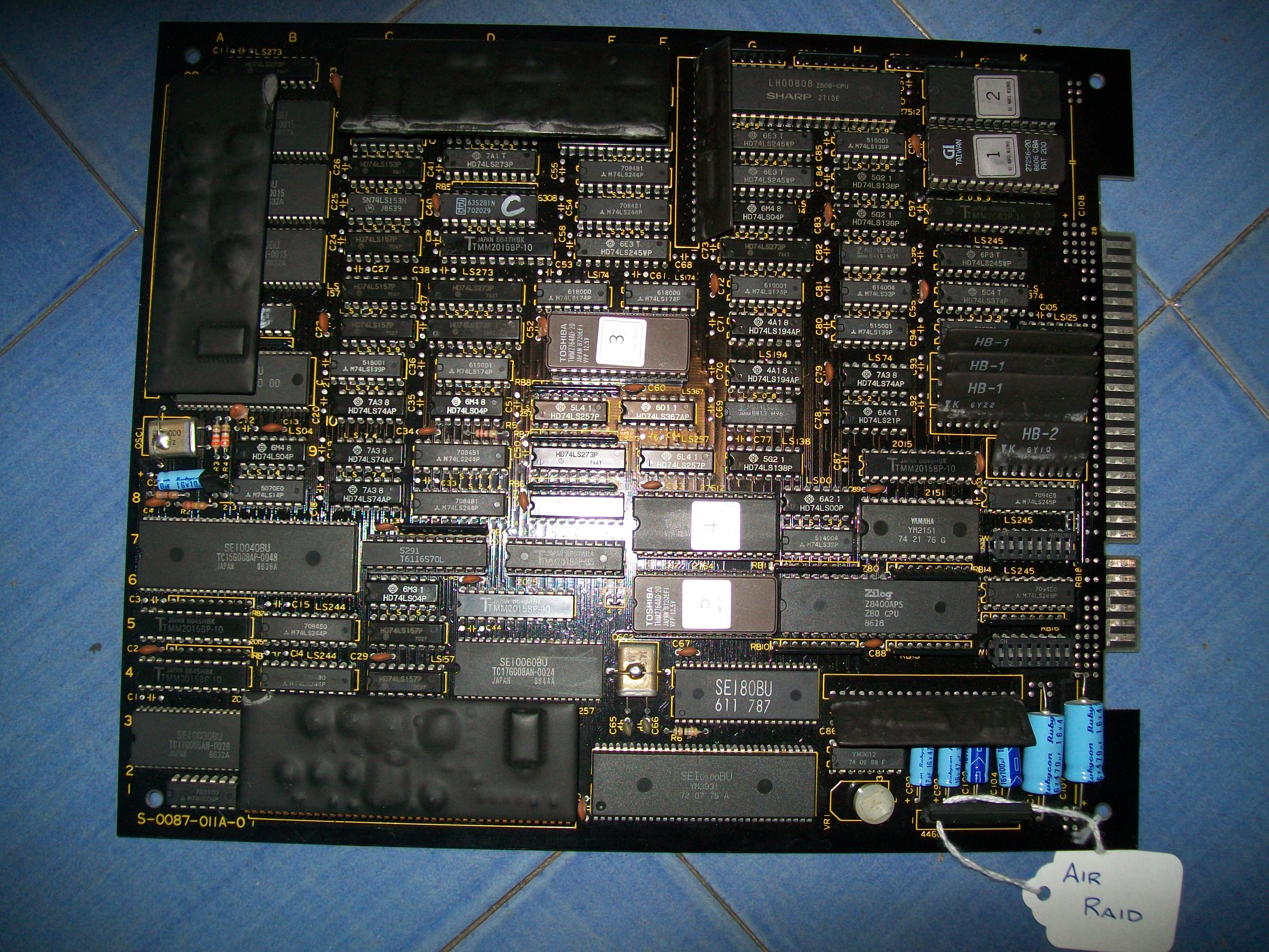
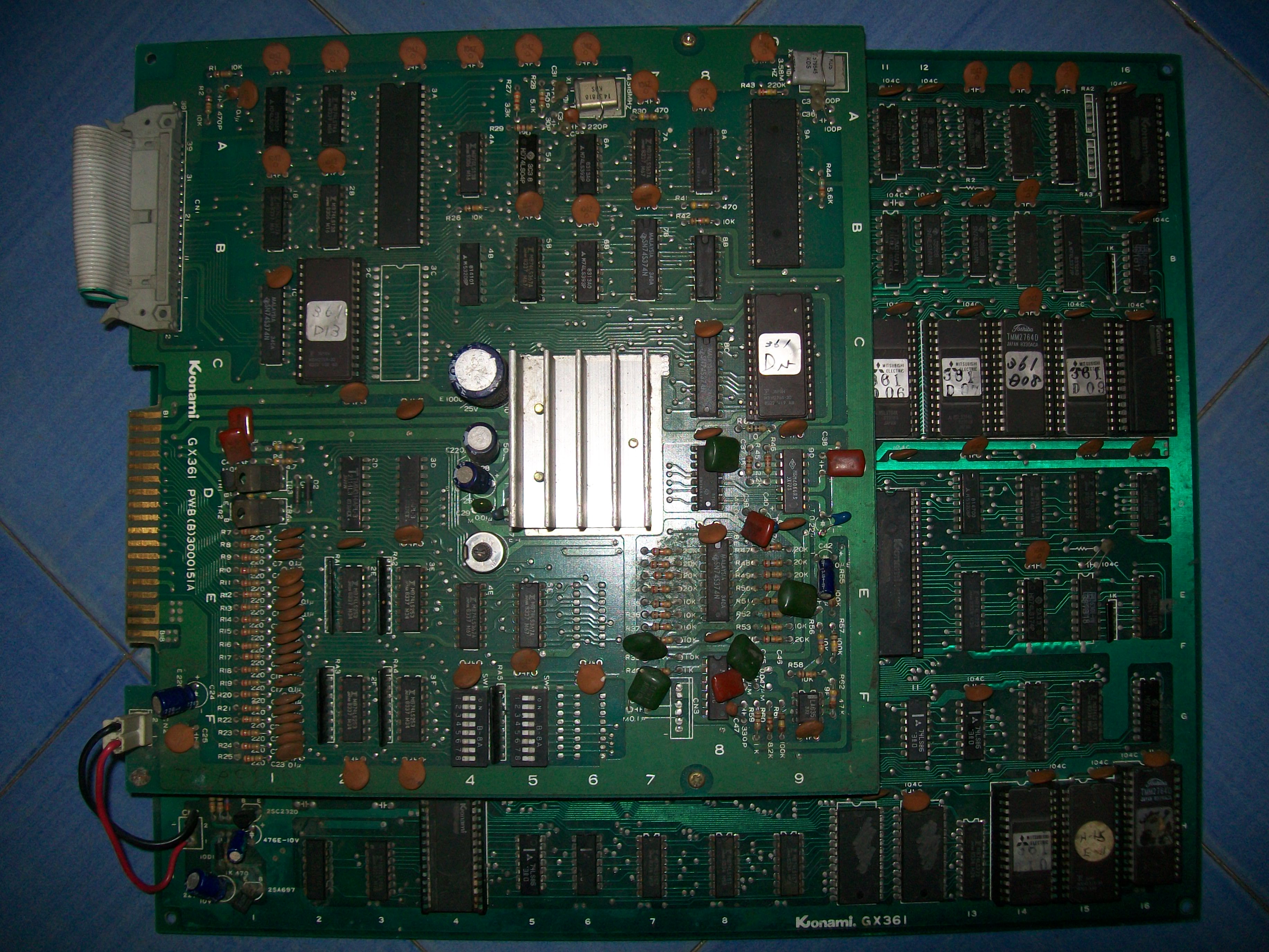
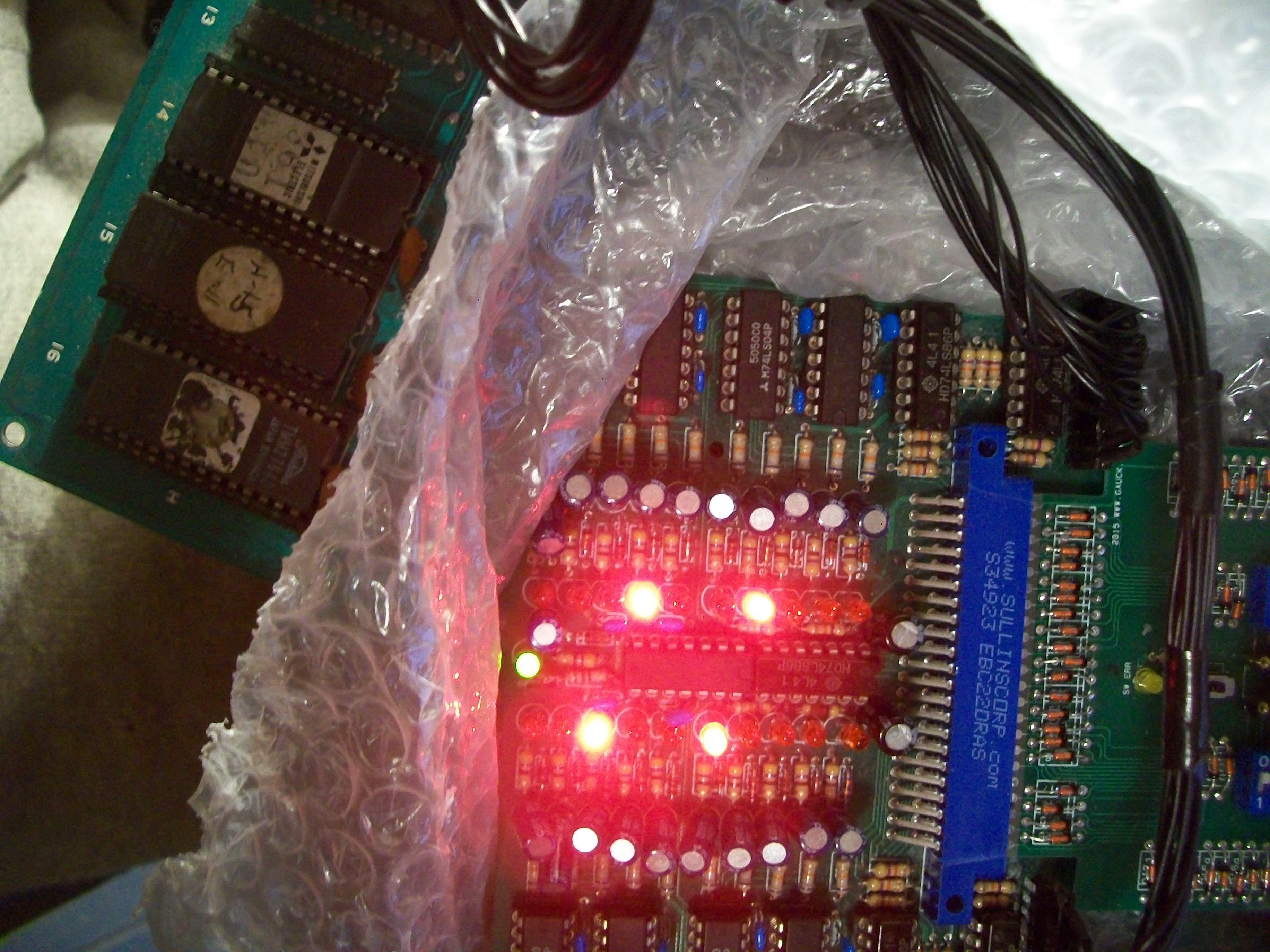
Some days ago I had on the bench for a repair this pretty rare Air Raid PCB (manufactured by Seibu Kaihatsu) :
As you can see from picture above hardware use some big SIL modules which contains all tiles/sprites data (currently undumped but MAME team is working on).My board was faulty, it has sever graphics issues :
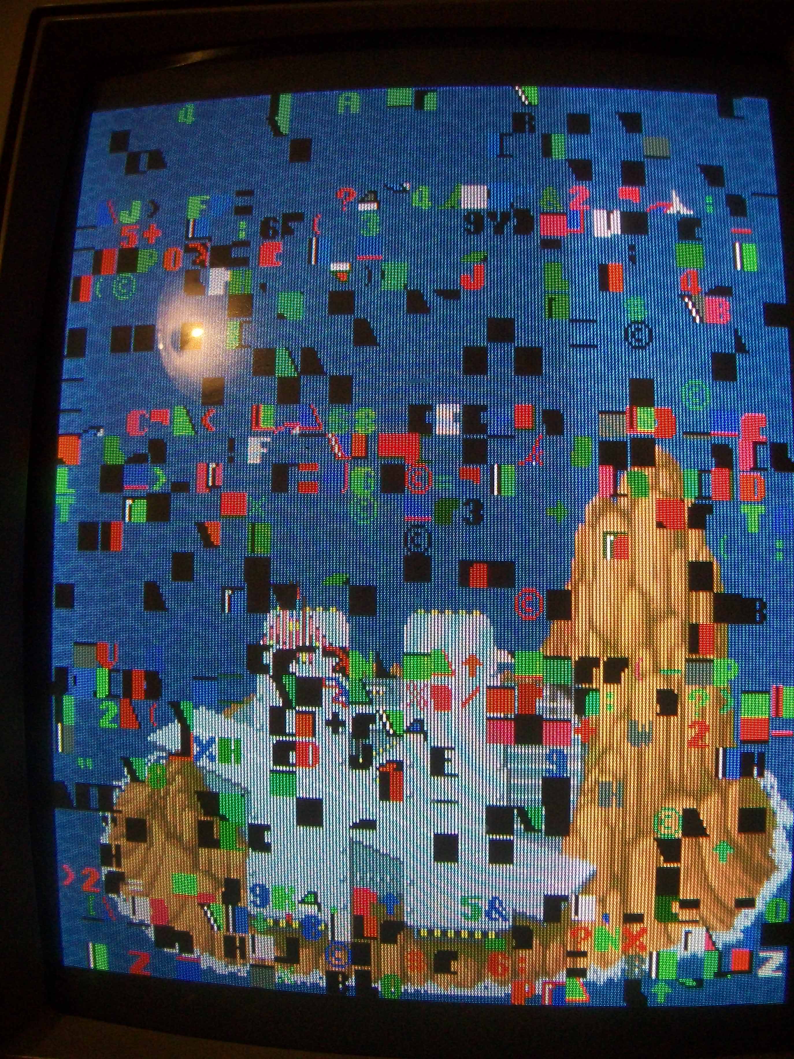
Tiles was filled with garbage :
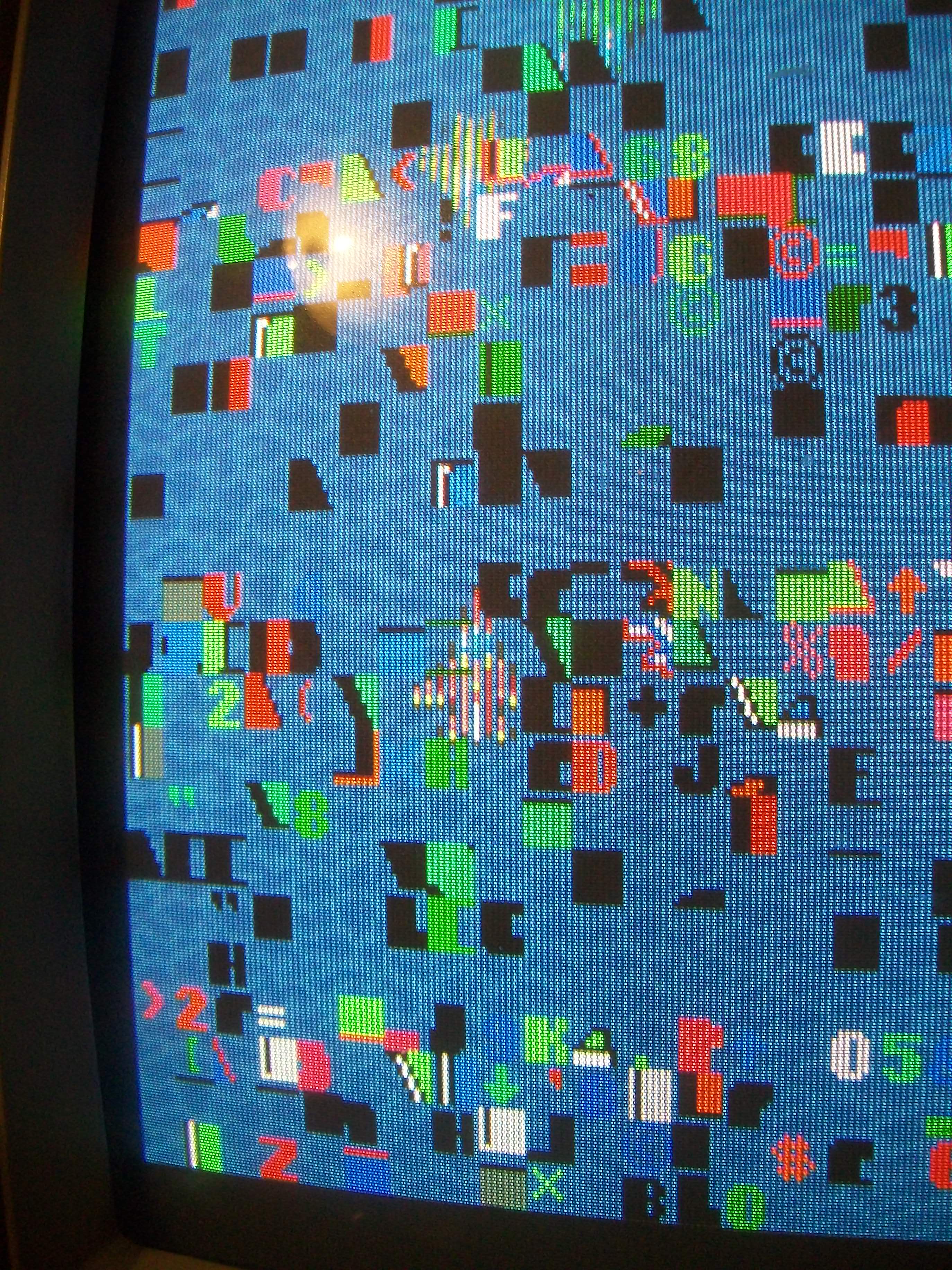
And sprites had blank lines through:
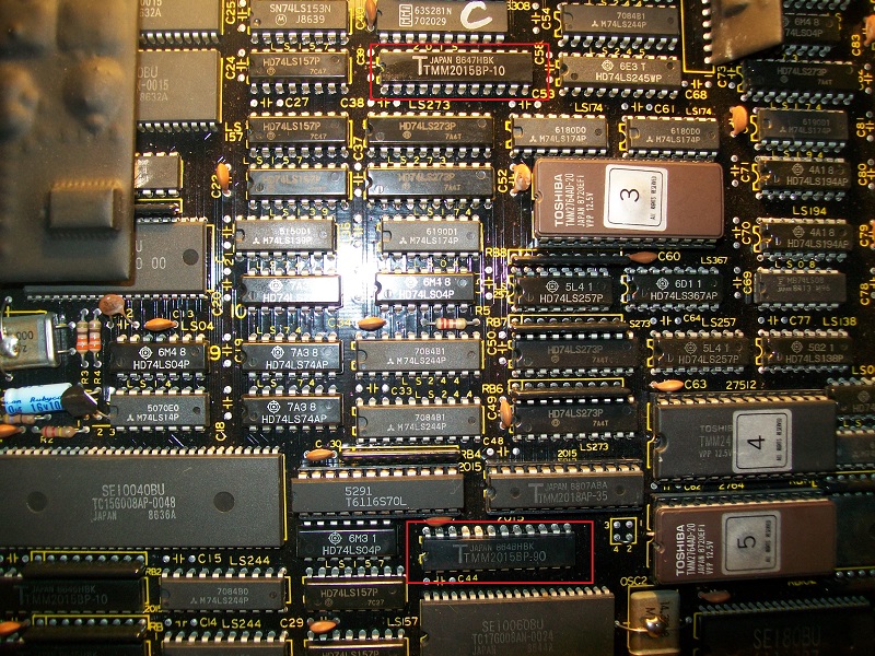
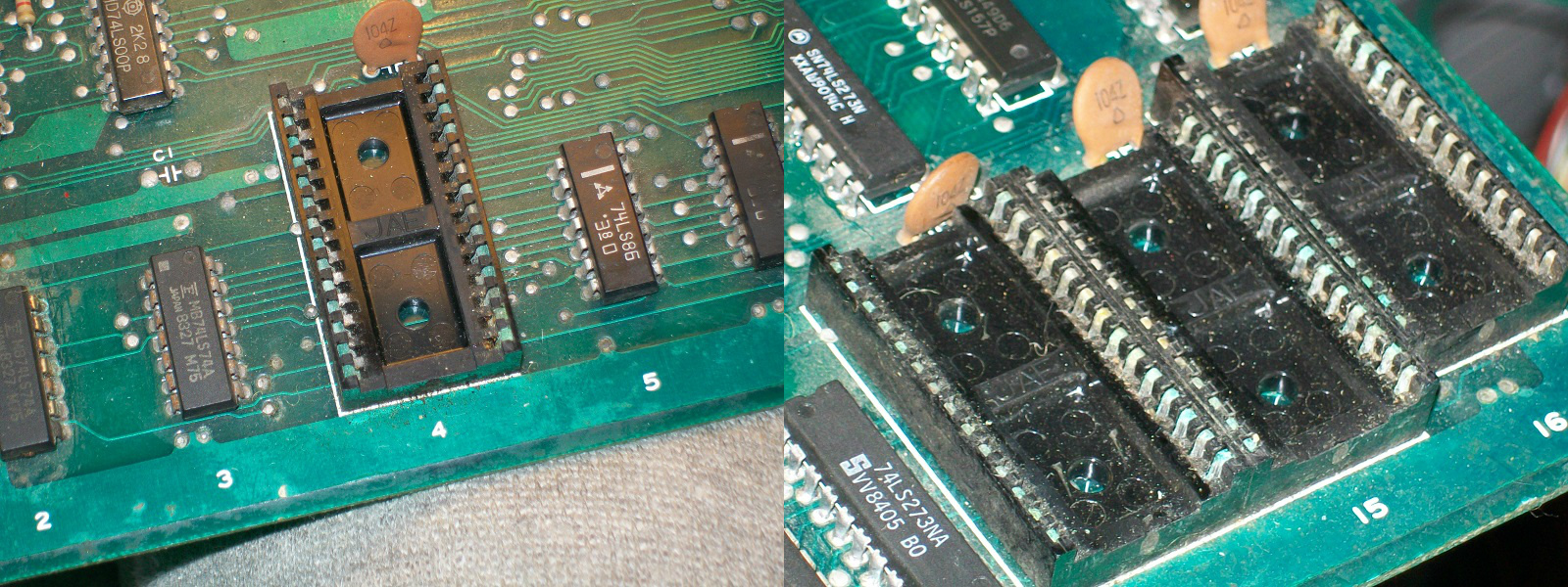
PCB was in almost mint state, only two 2k x 8-bit static RAMs replaced.Besides, it was fully populated with Hitachi TTLs which are very reliable.So, my suspicions fell on the remaining RAMs (more than on SIL modules) since they were all TMM2015 (like the already replaced ones, all 6116 pin to pin compatible) which means high chance of failure
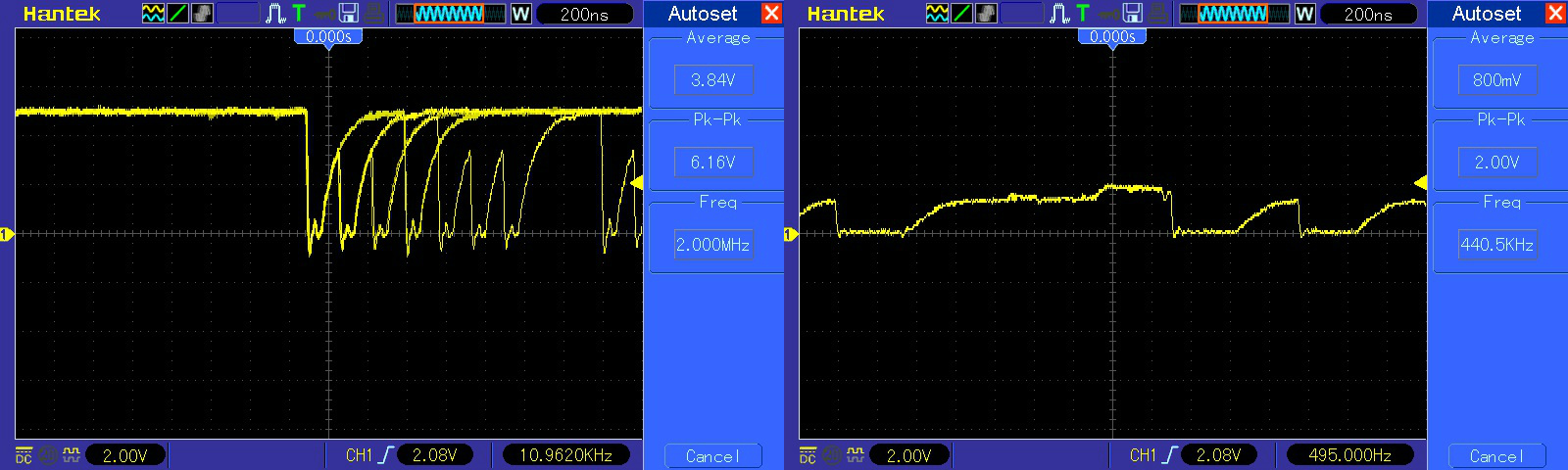
Probing the two @6D and 14D revelaed unhealthy signals on data lines:
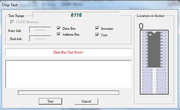
They failed when tested out-of-circuit:
Replacing them restored graphics completely.End of job.
Received for repair this original Track & Field (manufactured by Konami but actually it mounted the Centuri ROM set)
On power up it showed almost nothing on screen, most of graphics were missing, only some sprites were barely visible:
On a closer ispection board was corroded especially in the backgrounds generation circuitry, both sockets and inserted ICs ( the ‘082’ custom and the three EPROMS) were affected:
I replaced the sockets, rebuilt the ‘eaten’ legs and cleaned the oxidized ones but this didn’t improve anything.All the graphics is generated on bottom VIDEO board and most of the logics were from Fujitsu (which means an almost certain failure) so I went to probe TTLs with my logic comparator and found a bad 74LS157 @9H (its outputs generate some address lines for the two 2018 tiles RAMs)
This improved a lot, more graphics were displayed :
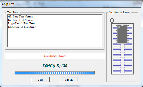
Always probing in-circuit the Fujitsu TTLs, I found a 74LS139 @14D with all floating outputs:
It obviously failed when tested out-of-circuit:
Now graphics were mostly present but gameplay was accelerated and sound missing too:
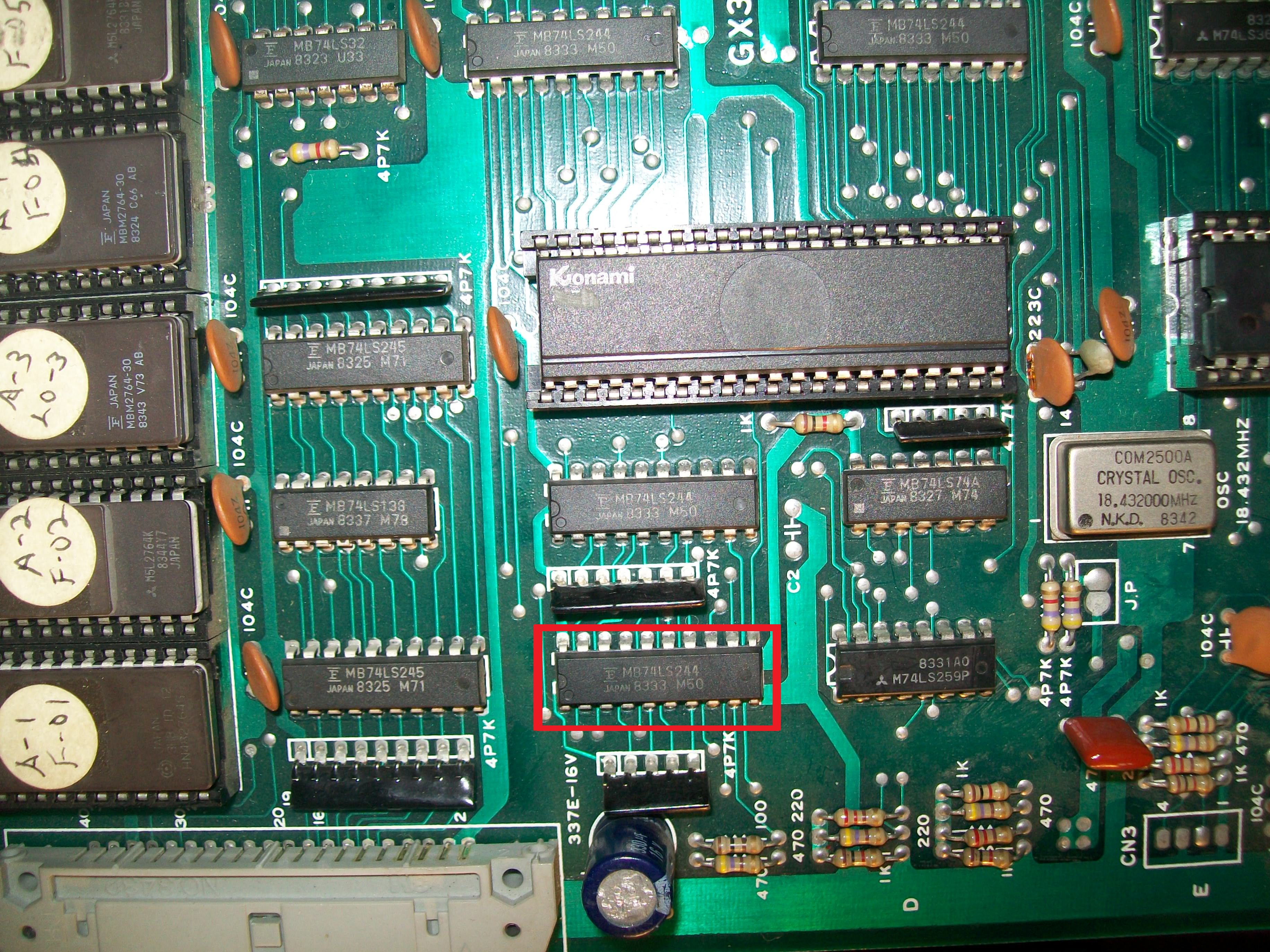
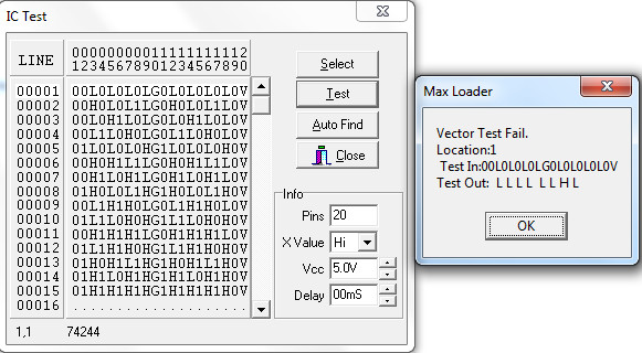
This is issue must have caused by some problem with main CPU, all the circuitry was on top board and also here Fujitsu TTLs were massively used.Probing around I found a 74LS244 @1C just near the Konami-1 CPU with some stuck outputs:
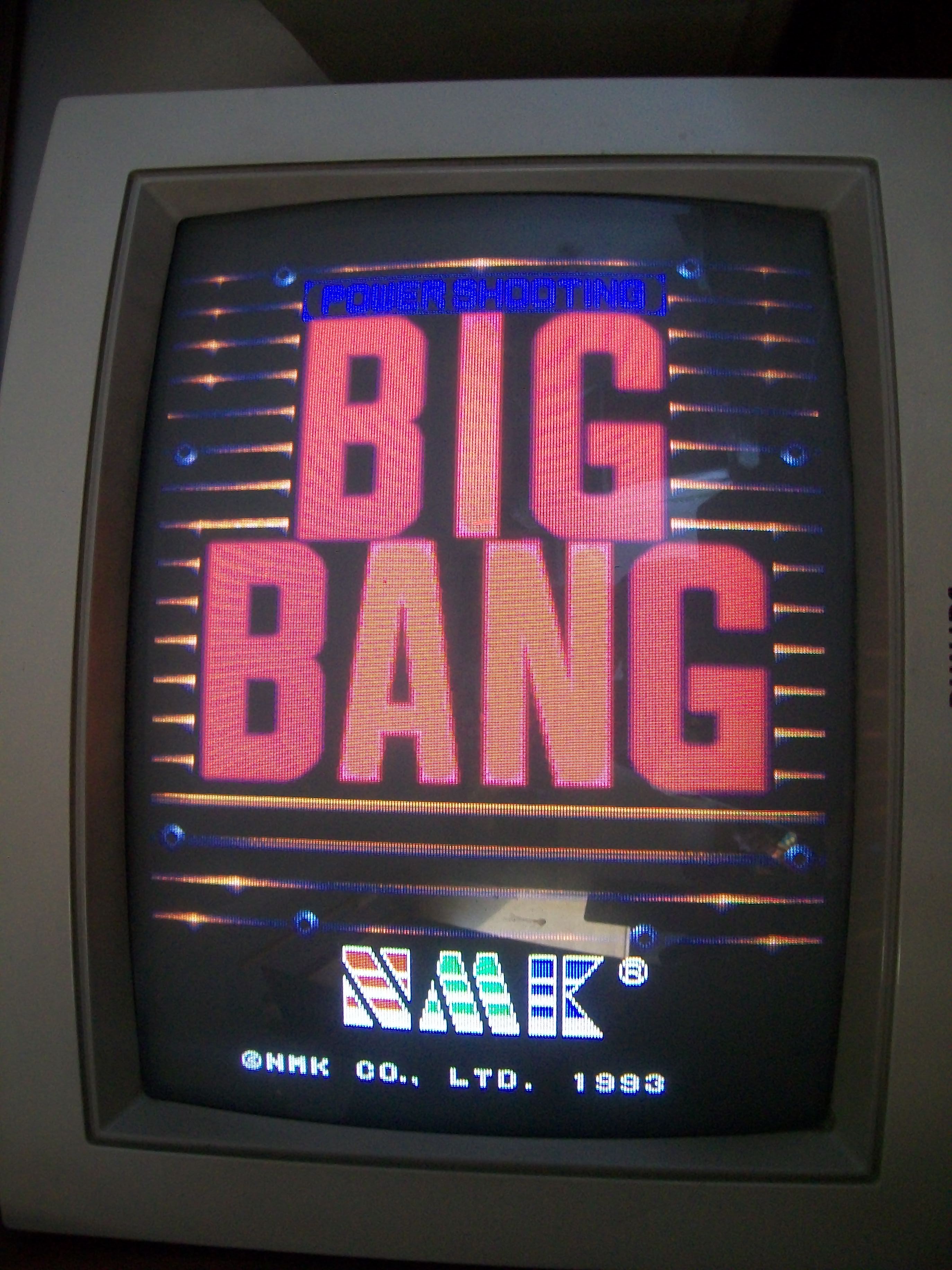
Replacing it restored completely graphics, speed and sound:
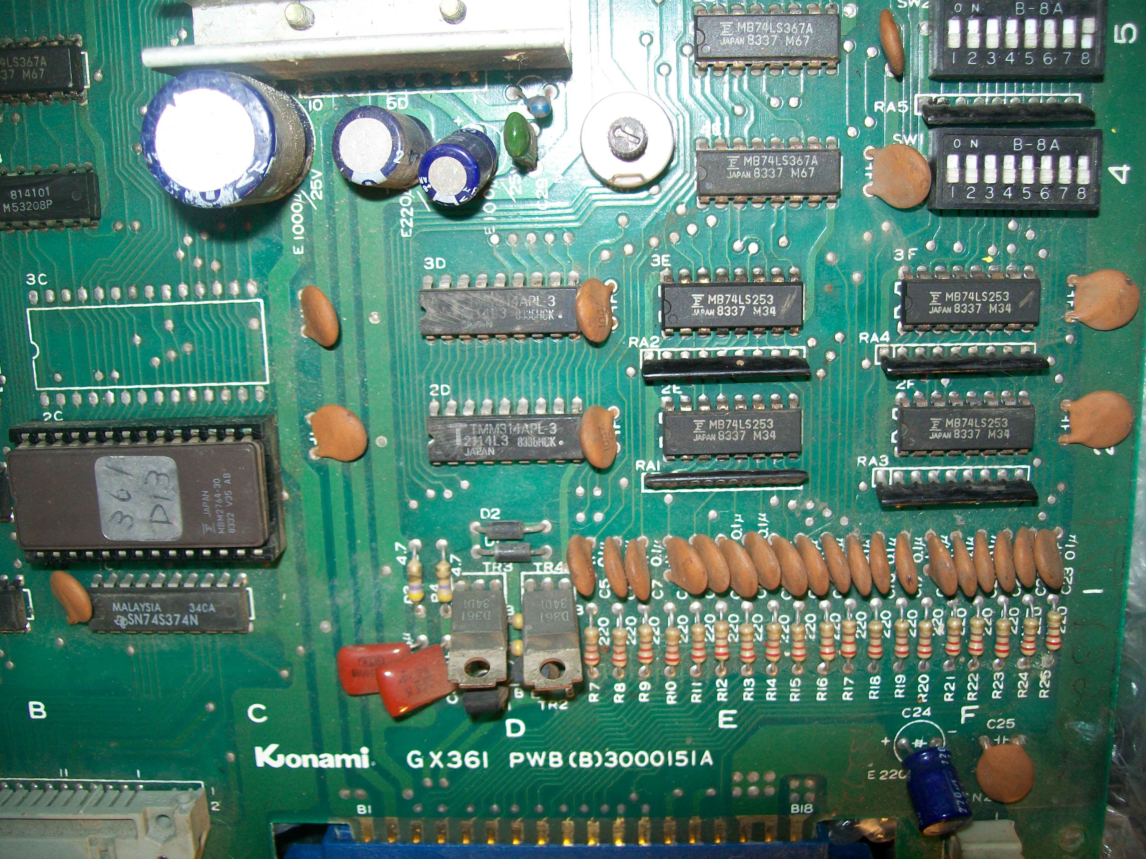
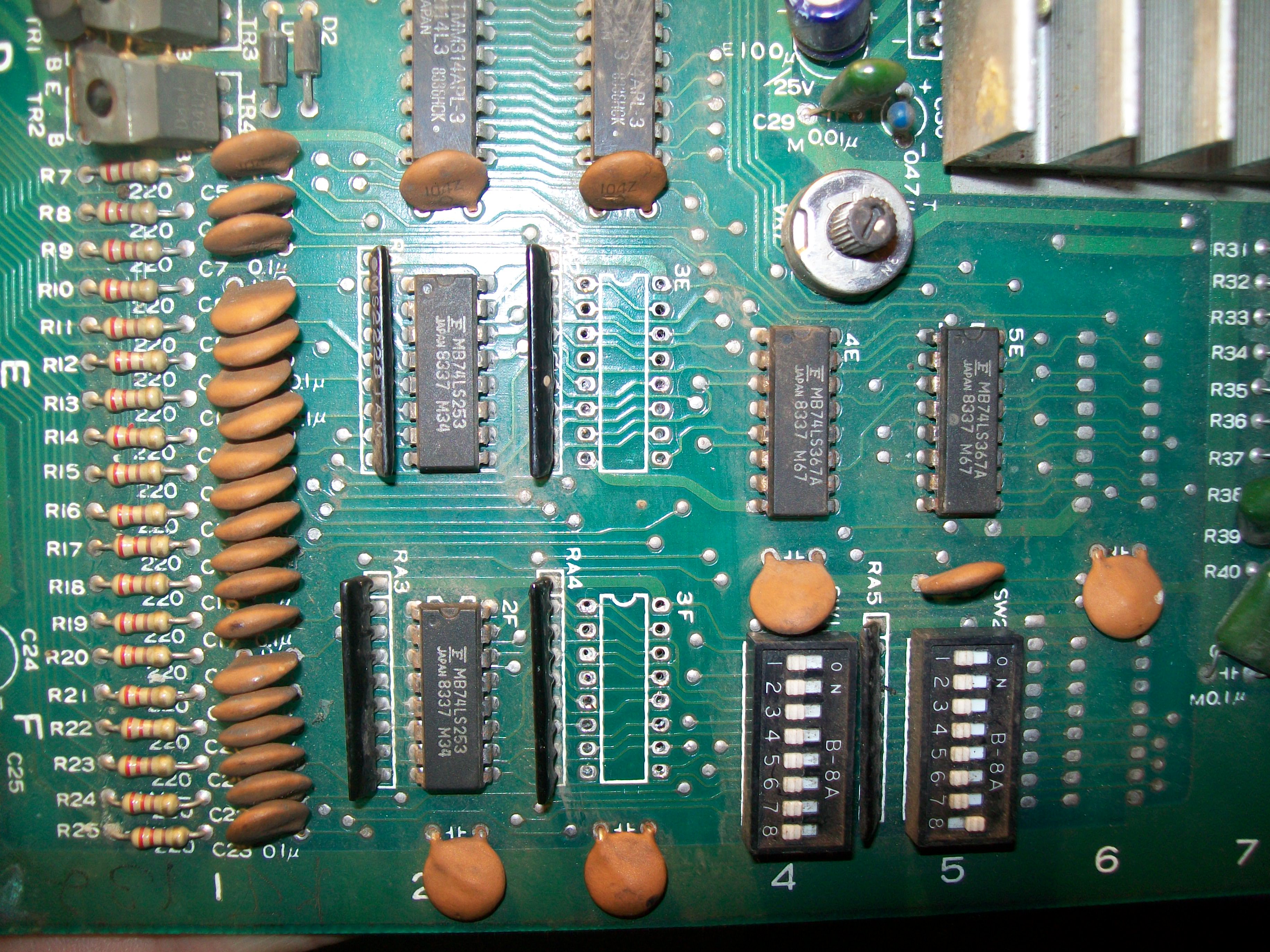
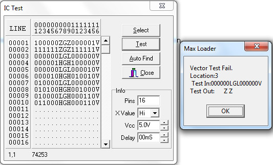
But I couldn’t coin up and start a game with both players, inputs were unresponsive.Tracing them back from edge connector they are tied to some 74LS253, from Fujitsu of course:
Without thinking twice I removed the two ones @3E-3F involved in P1 and P2 controls (the other two are for P3 and P4)
They both failed when tested out-of-circuit:
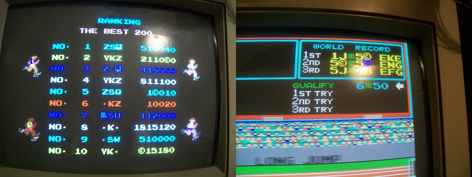
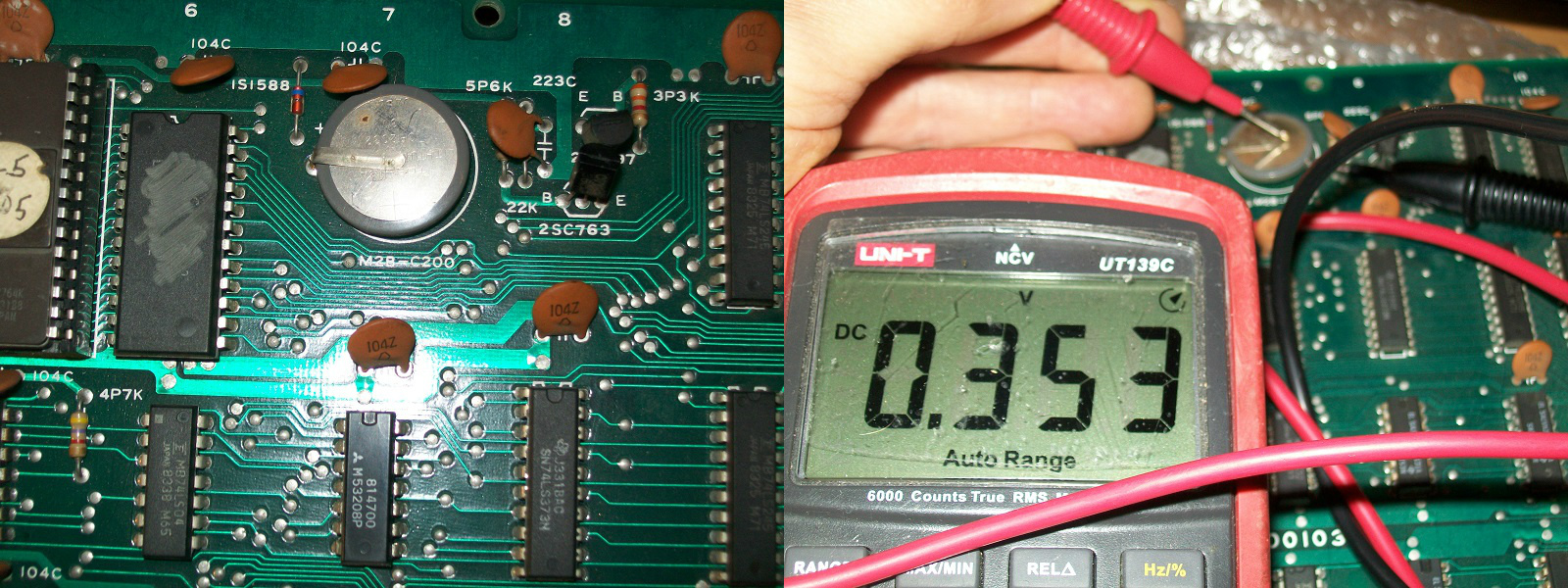
Now board played perfectly, the last issue I had to solve was that highscores and records were not saved, I got only some random characters instead:
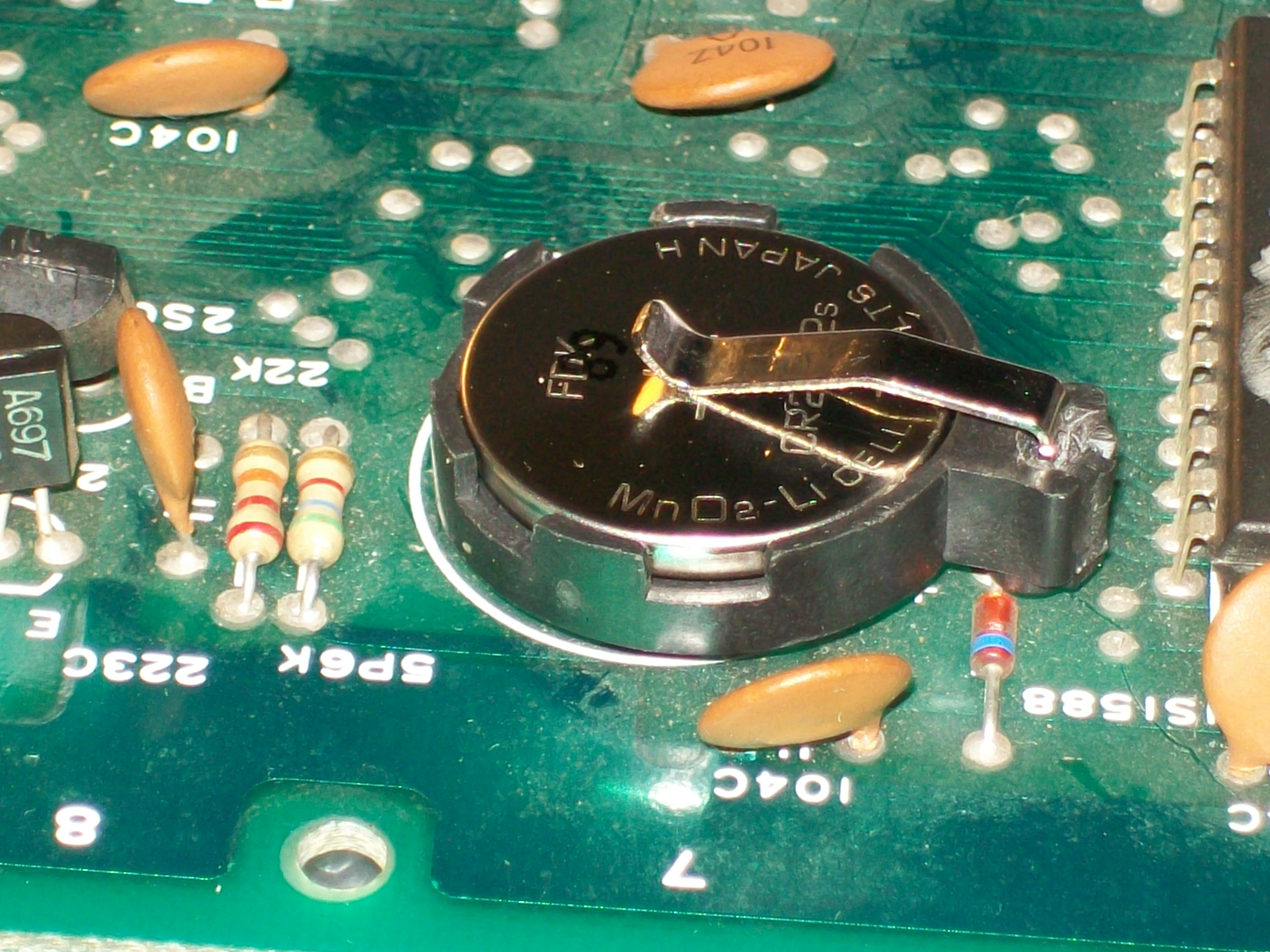
This obviously had to do with the +3Volt CR2032 battery installed on CPU board , it was really low (only few millivolts measured)
I installed a fresh battery with its holder to finish the job :


 :
: