Apr 032017
 

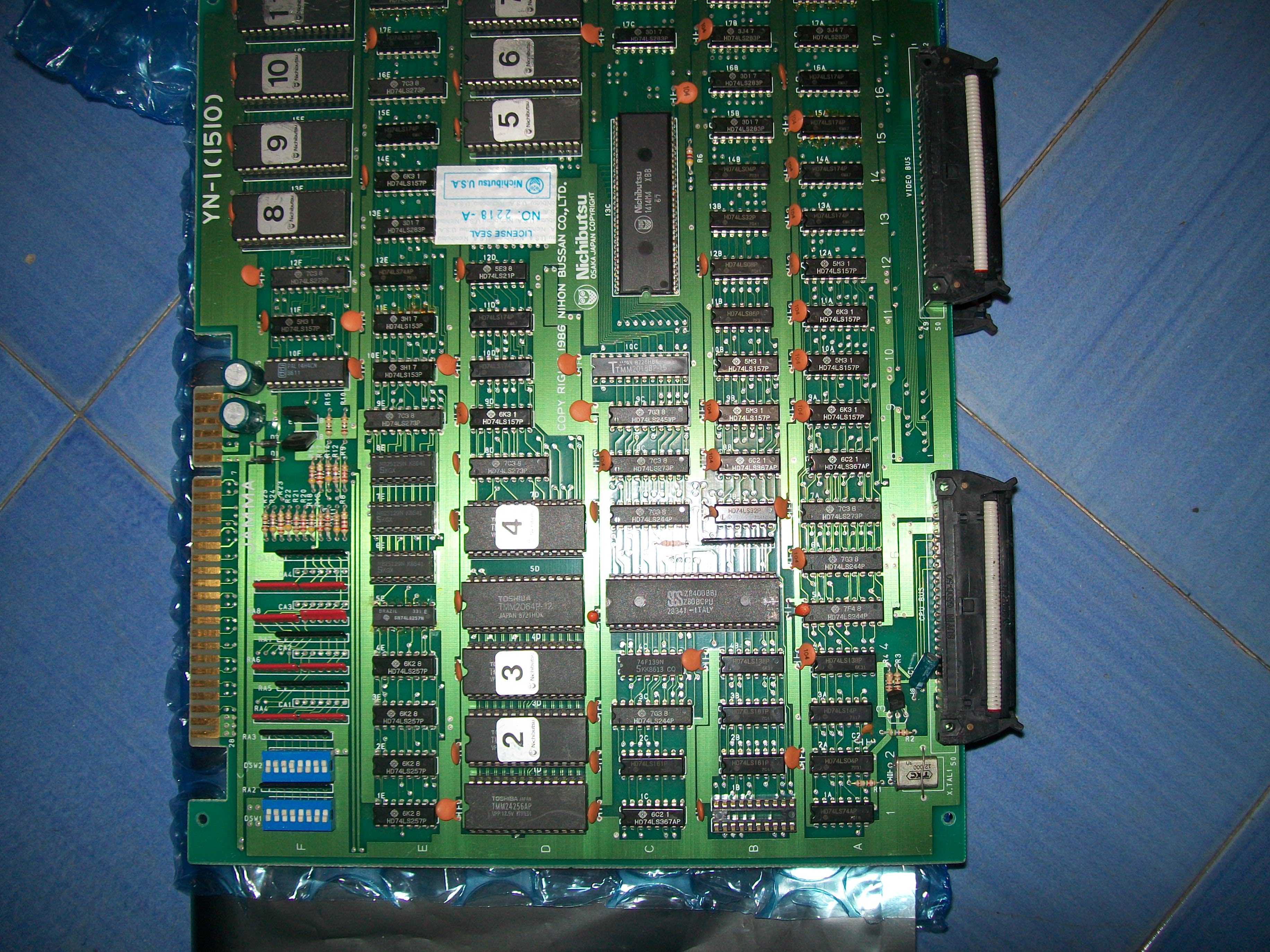
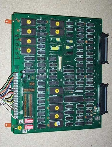
Received this original Ninja Emaki PCB (manufactured by Nichibutsu) for repair:

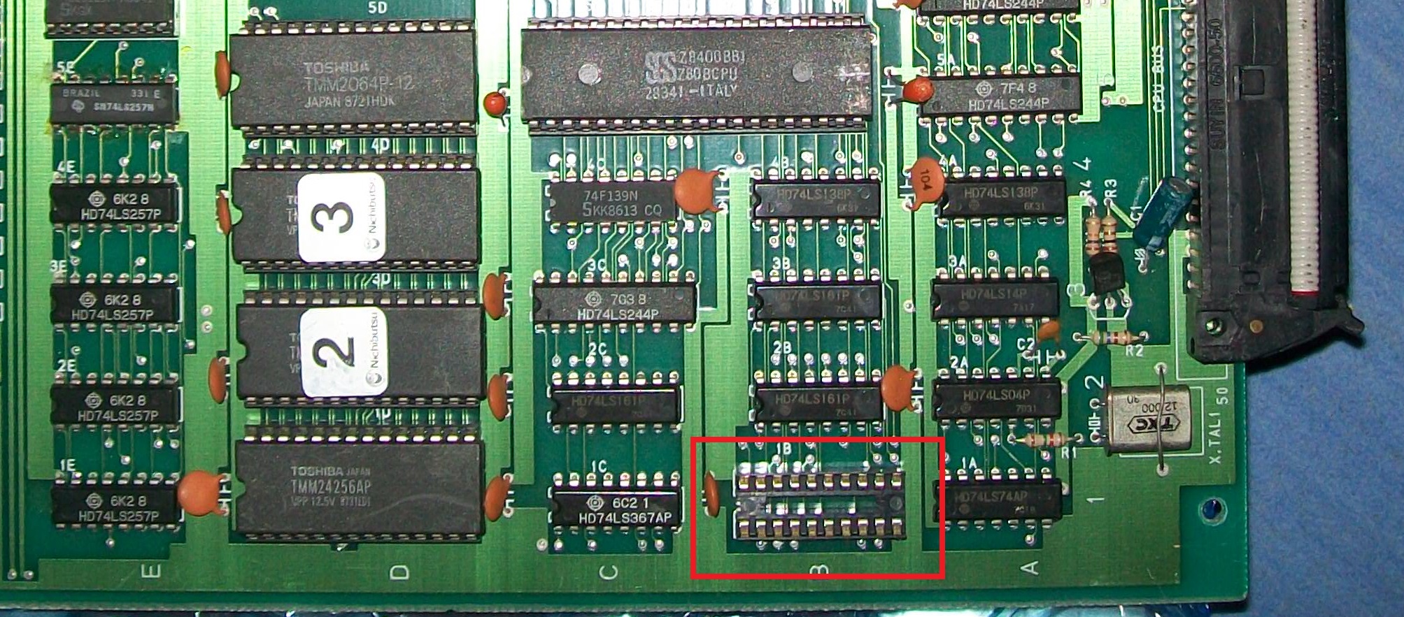
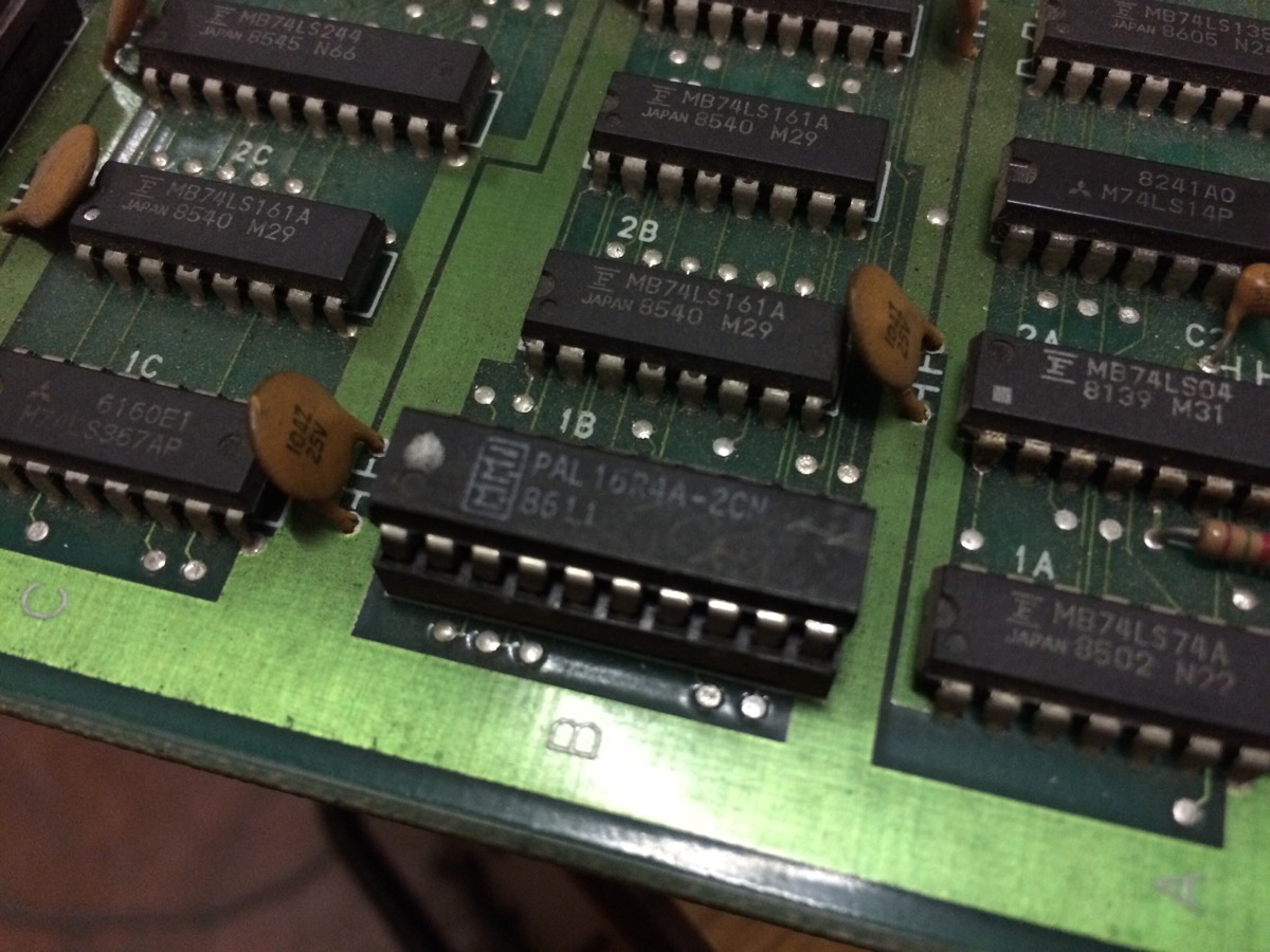
Board gave a solid black screen.After a quick visual inspection, I noticed one IC was missing from its socket @1B on CPU board:

My searches confirmed the missing IC was actually a PAL but sadly I had no access to other same PCB in order to read or reverse the device.Here bootlegs come handy since often they are perfect reproduction of the original hardware and, judging from pictures I found online, this was my case :

I quicky managed to find a Ninja Emaki bootleg and one received it I realized that the missing IC was a PAL16R4 so a secured registered PLD hence not readable or reproducible :

My only choice was  to take this chip from the bootleg and install it on the original board.I made it and board sprang to life:


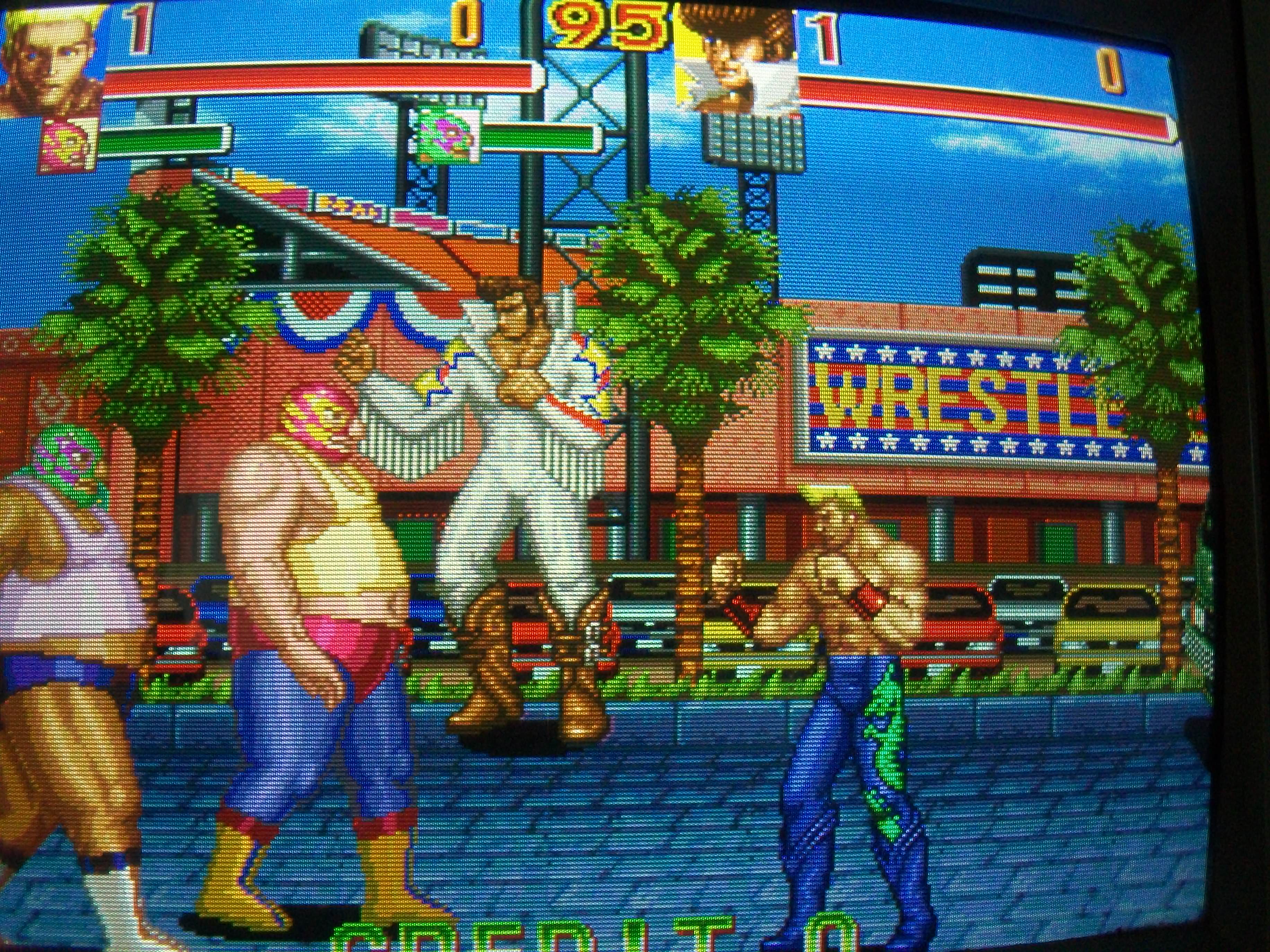
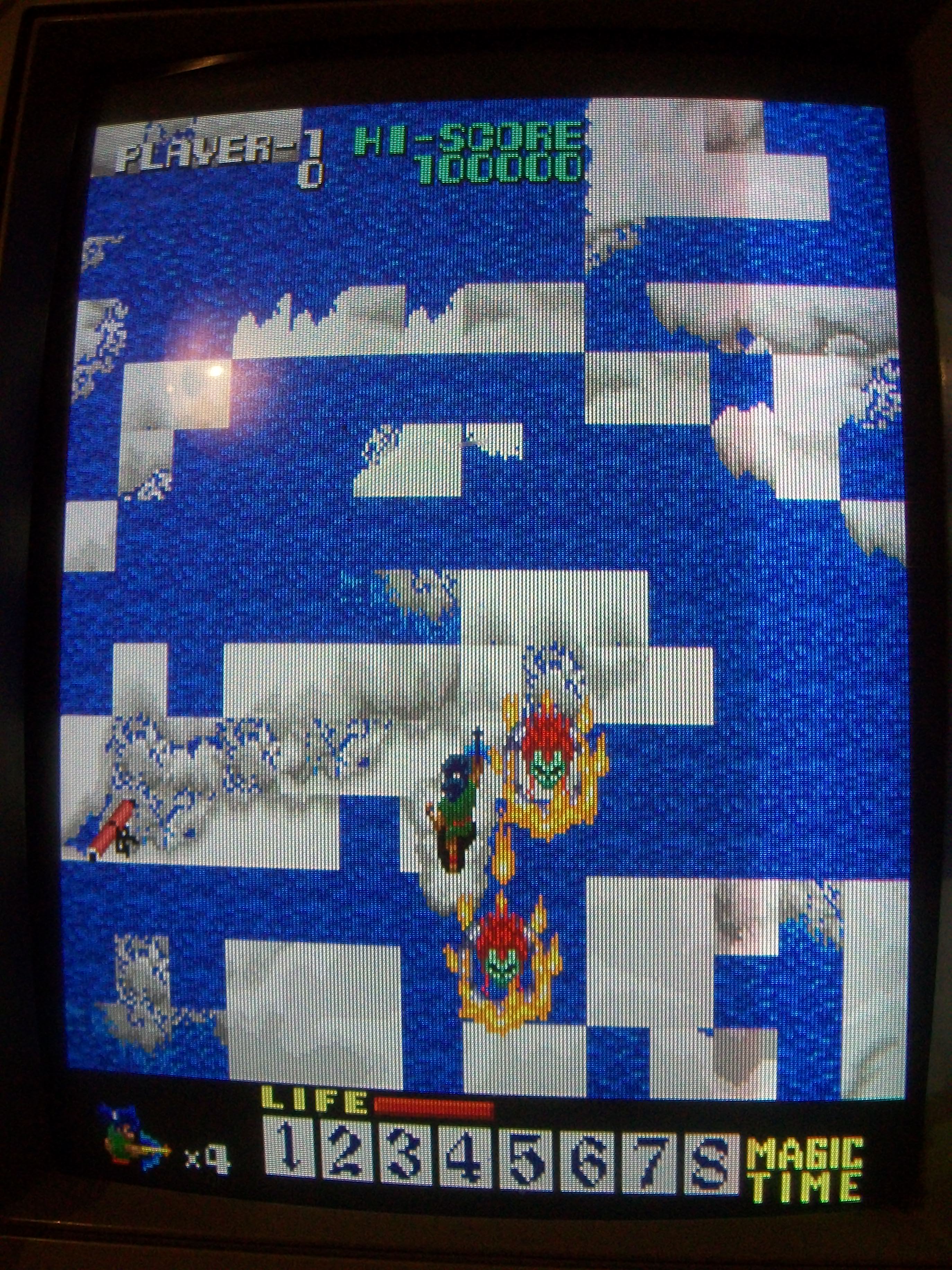
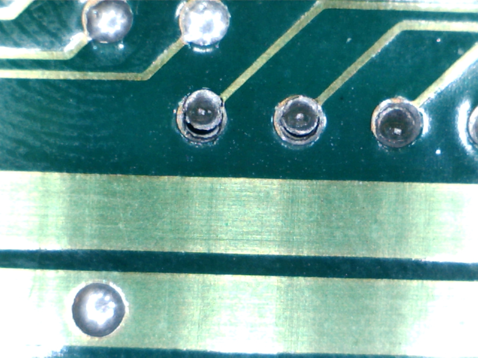
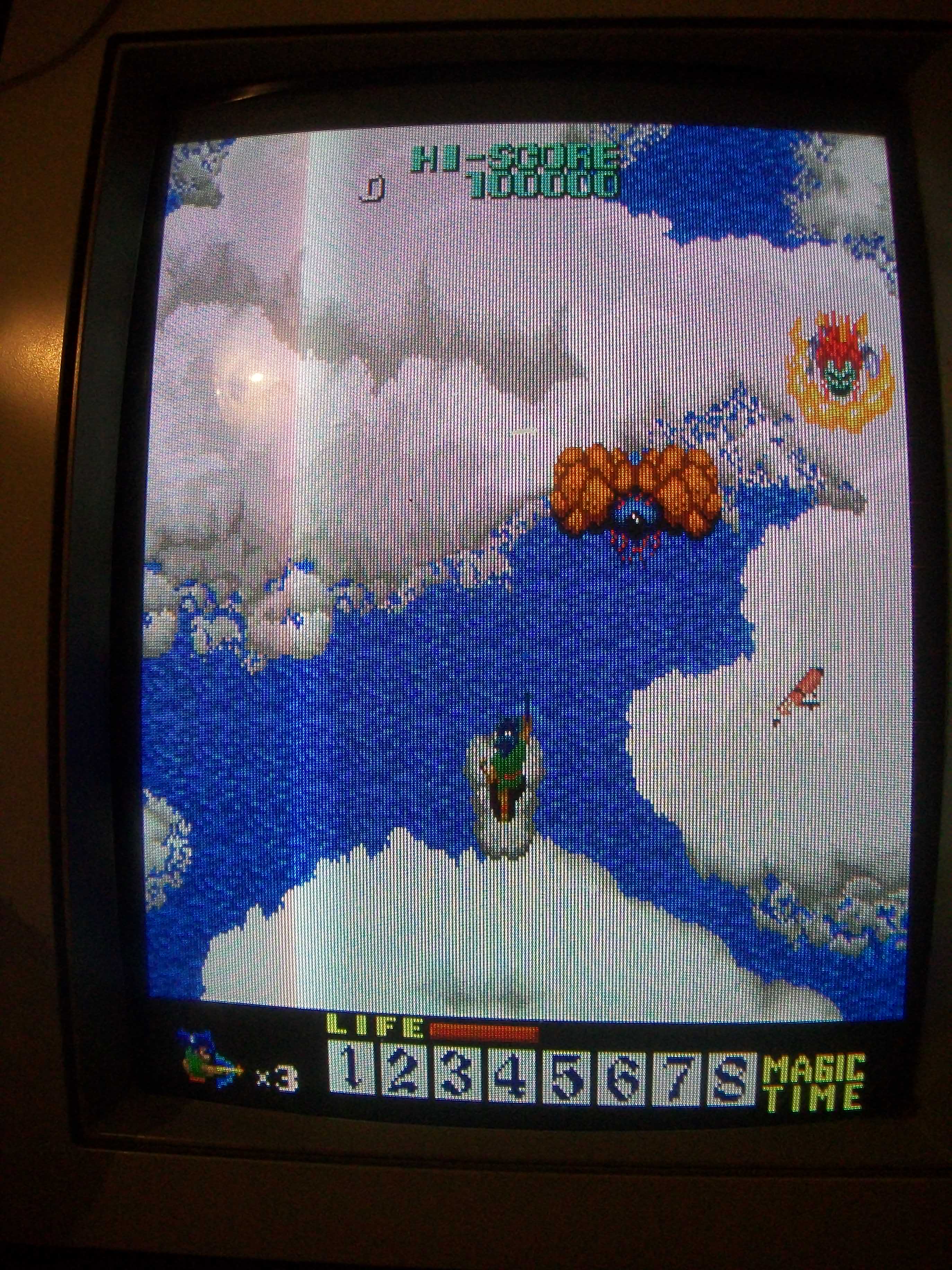
Game was playable but background were scrambled as you can see from above picture.I noticed that if I pressed or flexed the board in some points, the graphics came back in place.A closer inspection revealed some dry joints on solderside of an EPROM:

Reflowing them fixed the board completely.

 Posted by at 7:30 pm

Rabio Lepus repair log

 PCB Repair Logs  Comments Off on Rabio Lepus repair log
Mar 292017
 

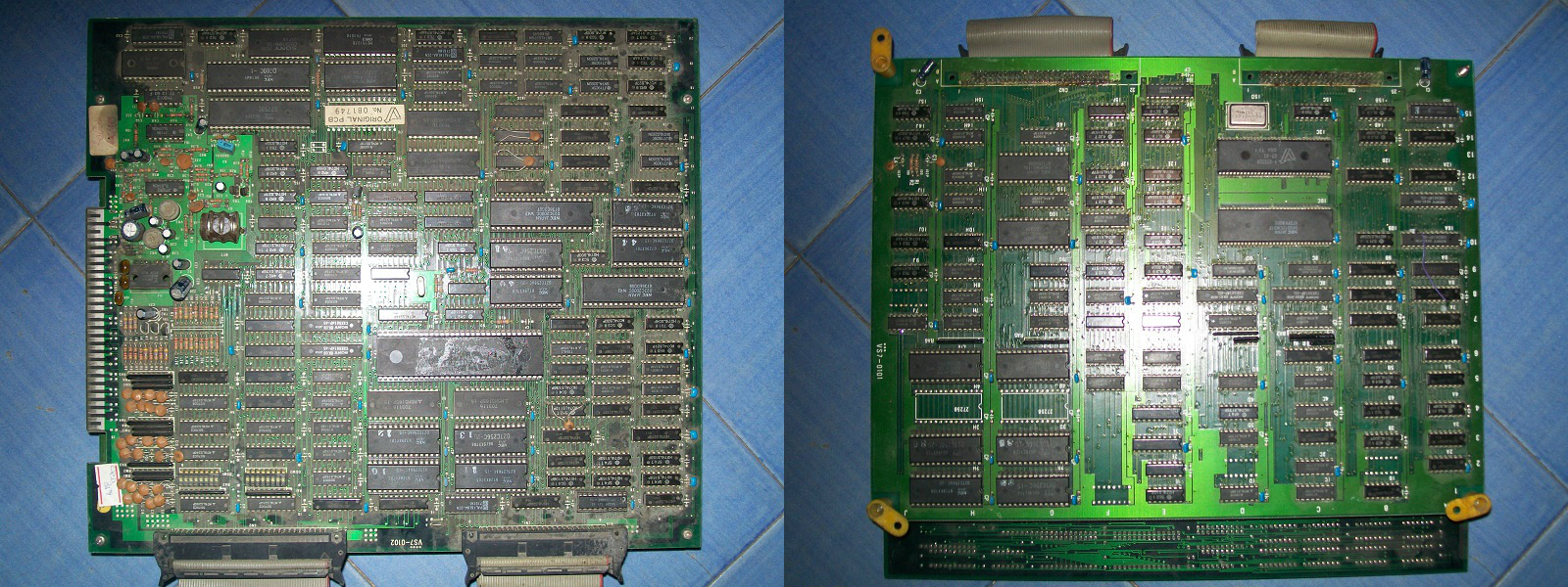
Got a Rabio Lepus (japanese release of Rabbit Punch, a cute shoot ’em up released by V-System Co. in 1987) in lot of faulty PCBs.Hardware is made of a CPU and a VIDEO board:

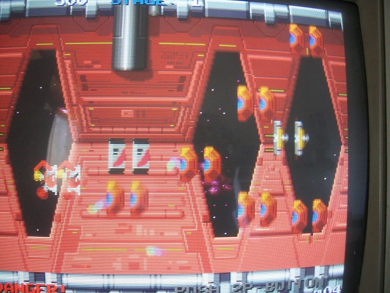
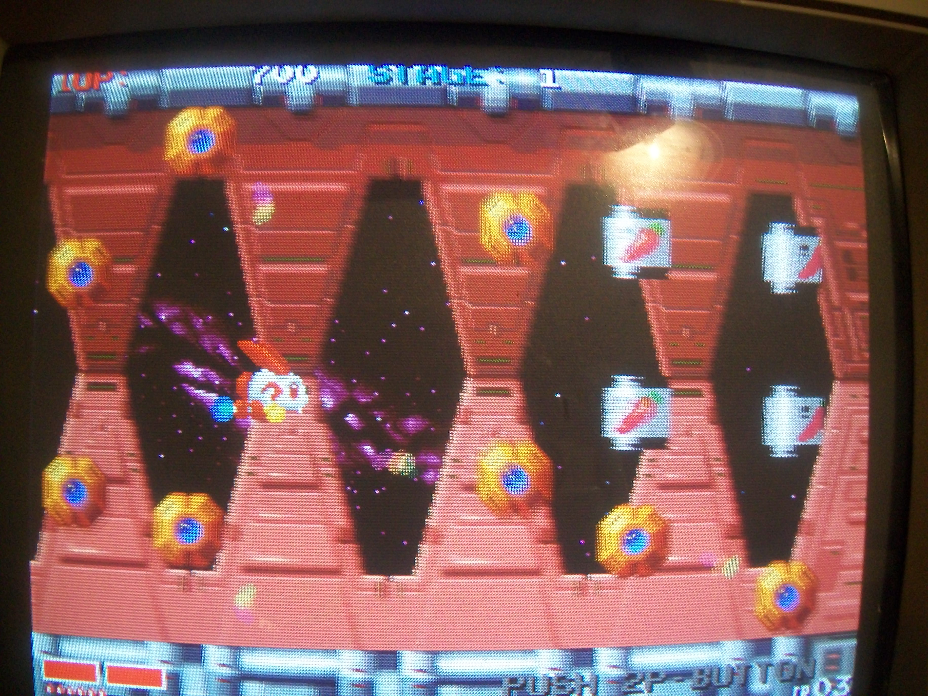
Board had a graphical issue, sprites were splitted and misplaced:


Usually this kind of problem indicates an addressing fault so wrong address are generated hence wrong data are read/written.Sprites data are stored in six devices (four 27C256 OTP ROMs and two 28 pin 1Mbit MASK ROMs)

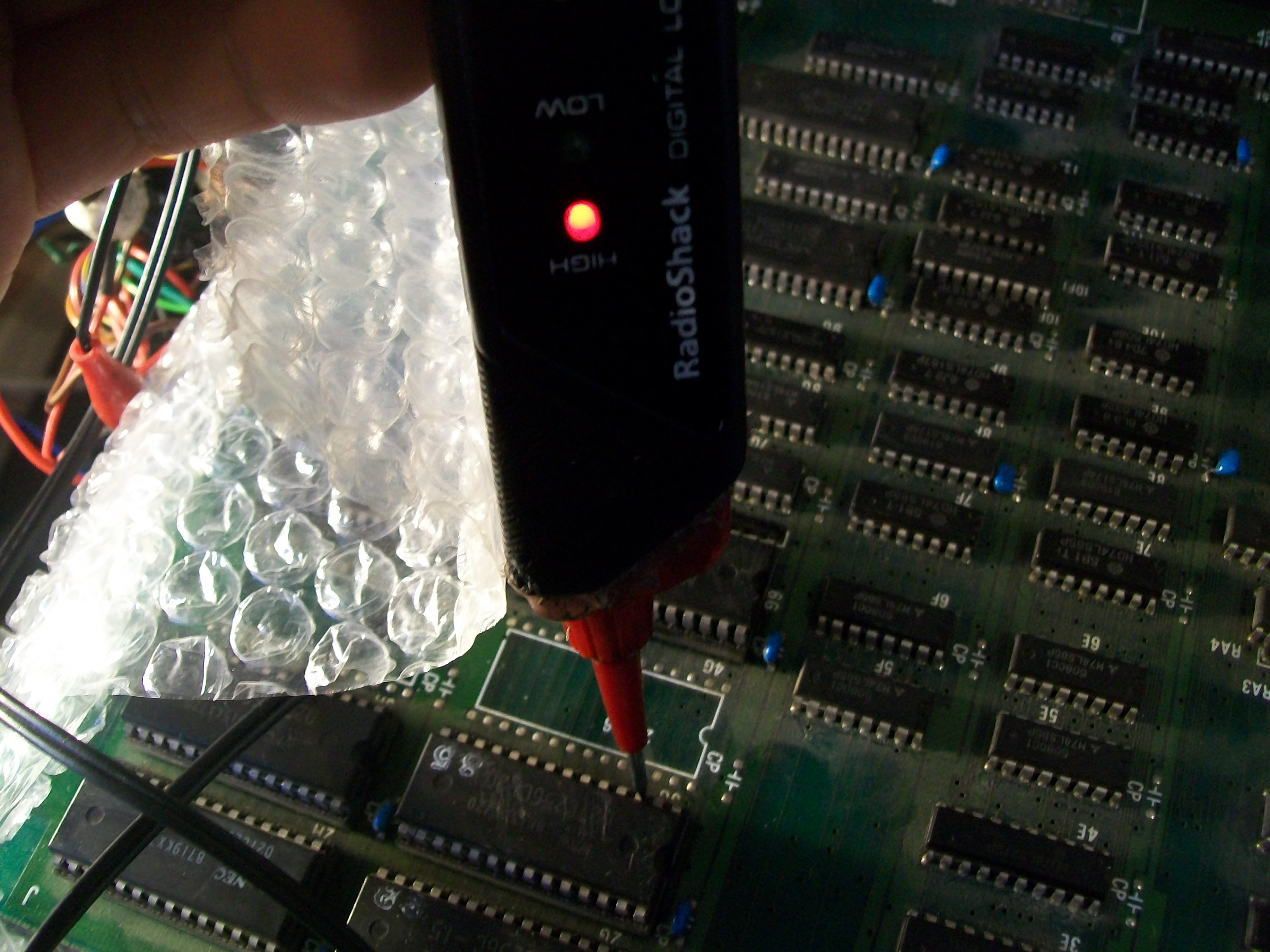
Reading them gave good dumps but the logic probe revealed that address line A7 was stuck high in all of them (address bus is shared)

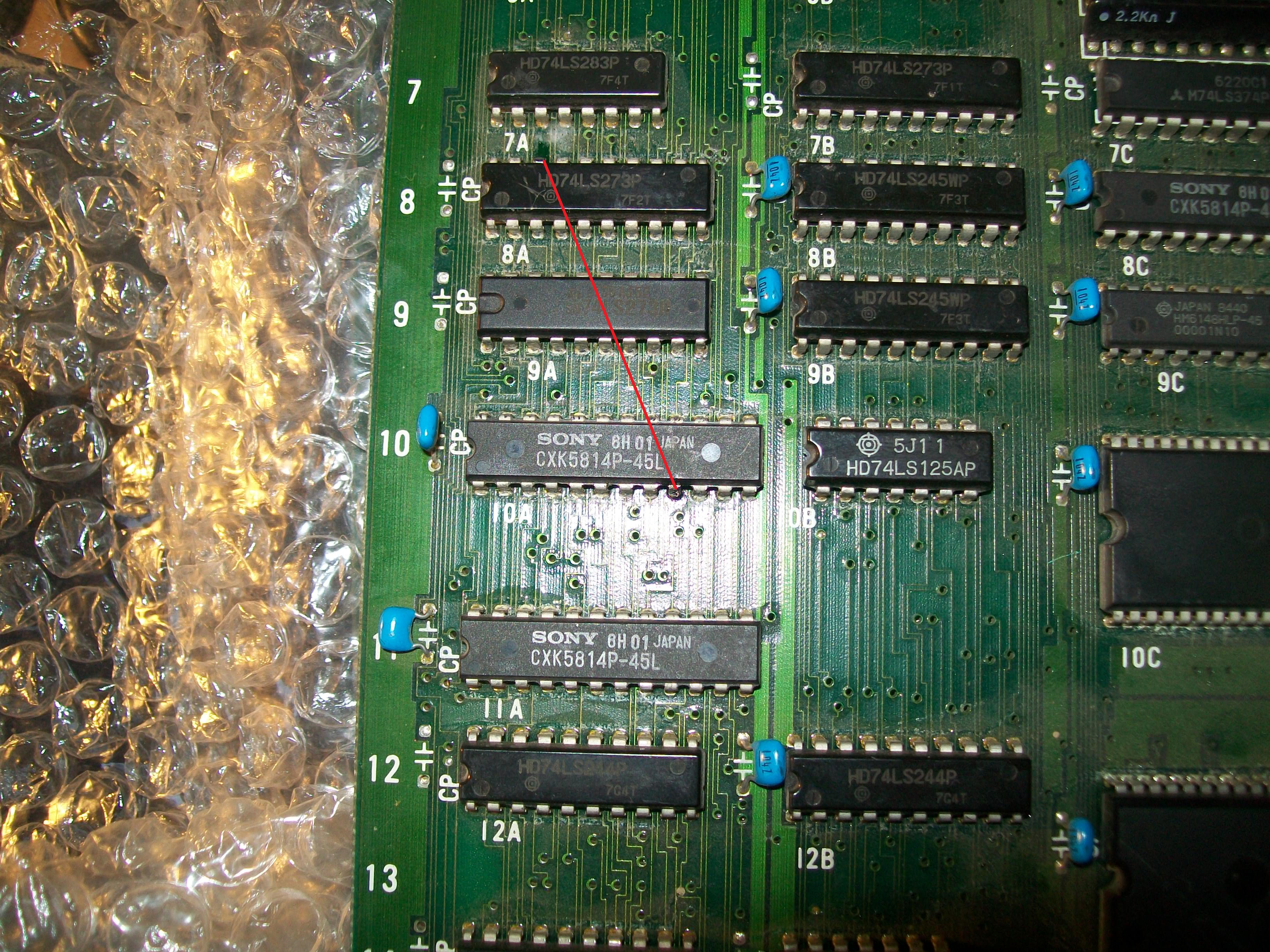
Tracing this address line back lead me to an output (pin 19) of a 74LS273 @8A, the corresponding input (pin 18) was floating.All the other outputs were active (generating the other address lines for sprite ROMs) and inputs were toggling too.Each input is connected to a data line of a near 2k x 8-bit static RAM @10A so following this logical arrangement I figured out that pin 9 (data line D0) of the RAM should have tied to pin 18 of the 74LS273 but it was not so :

I restored the connection with a jumper wire and this fixed the issue:

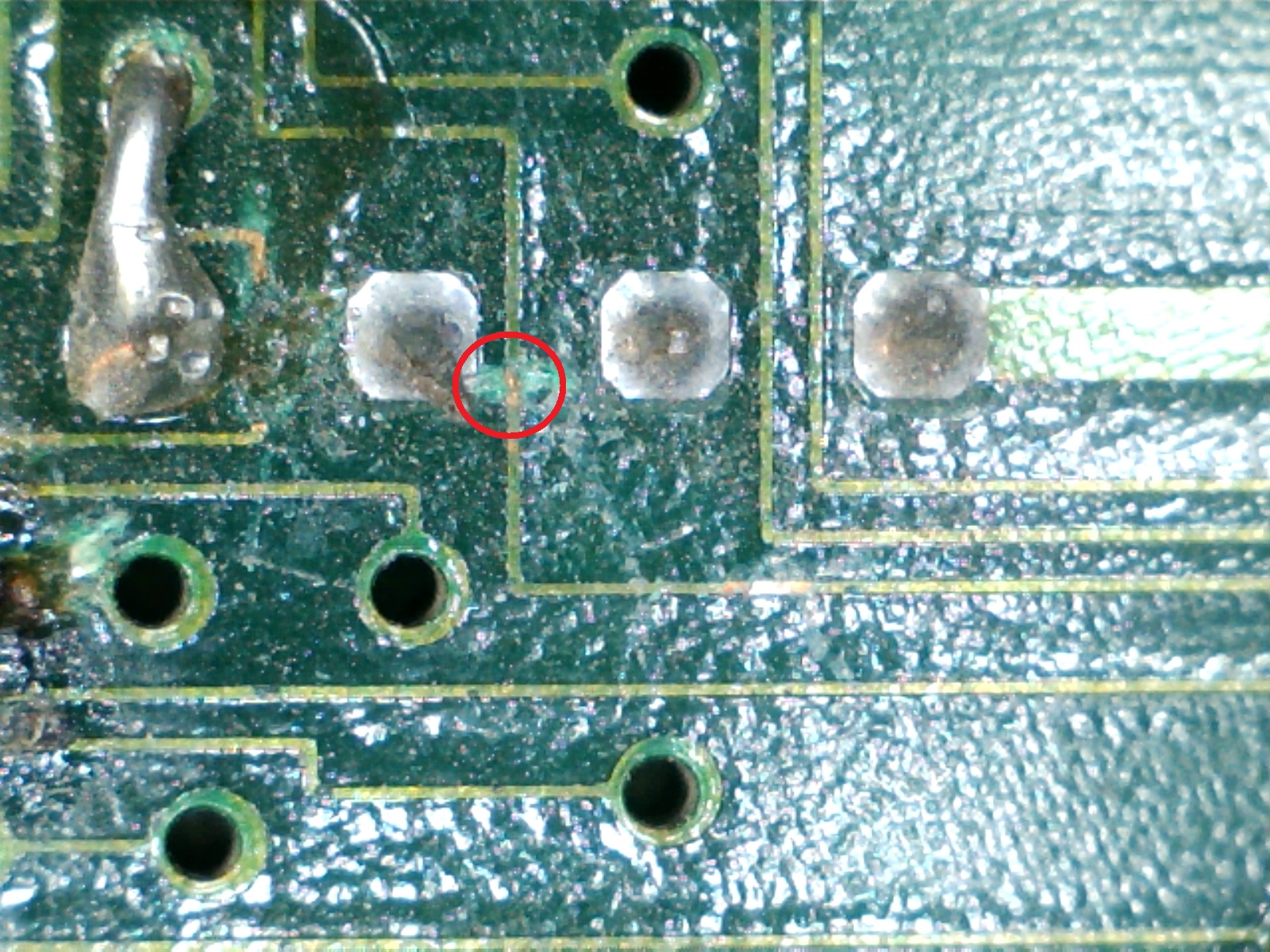
As I expected, doing a visual inspection on solderside revealed a severed trace:

End of job.


 Posted by at 6:20 pm

X-Men repair log #3

 PCB Repair Logs  Comments Off on X-Men repair log #3
Mar 192017
 

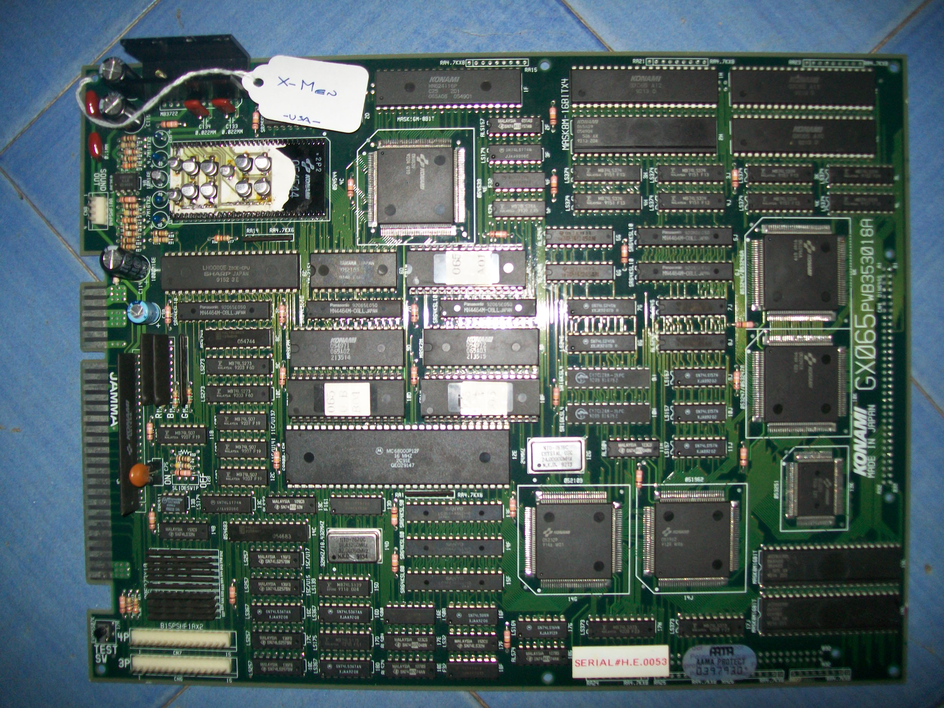
Got this X-Men PCB for a repair :

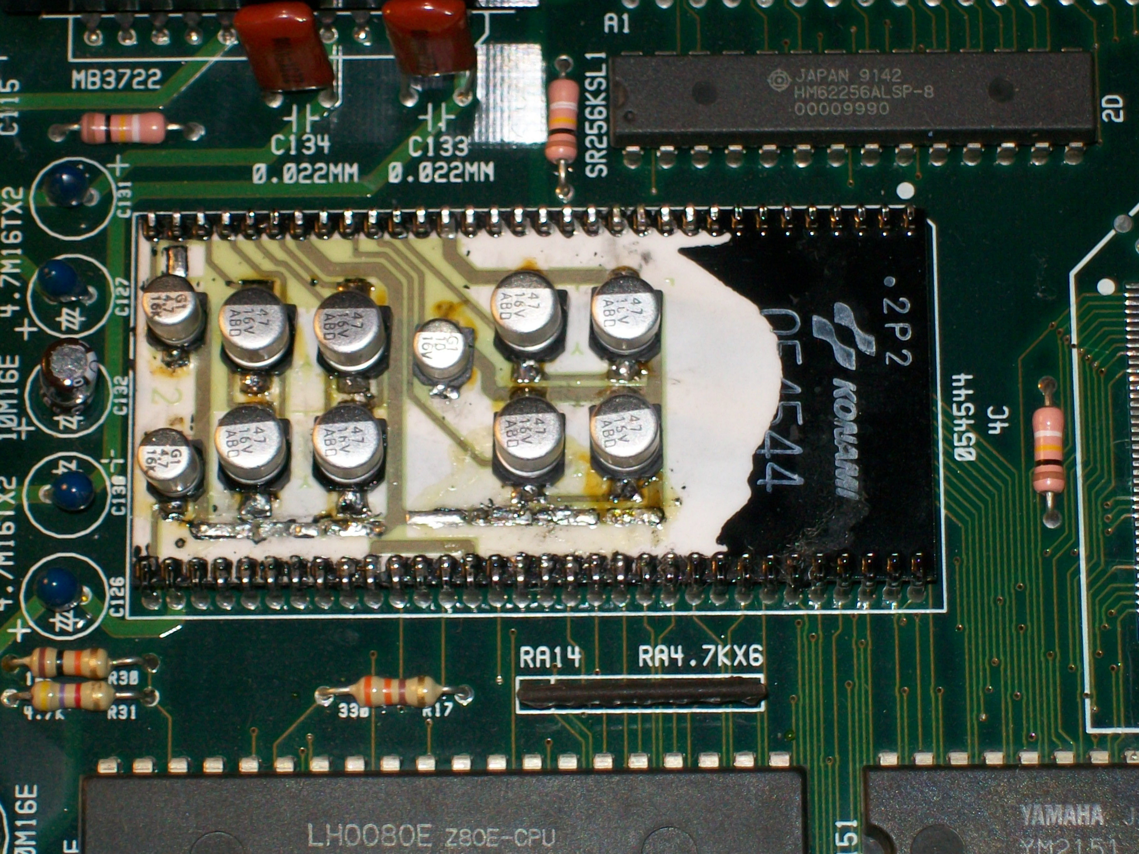
As often happens on Konami boards that use hybrid audio module (the ‘054544’ in this case) audio was horribly scratchy and loud:

Electrolytic capacitors  had already been replaced with same type but this obviously was not enough:

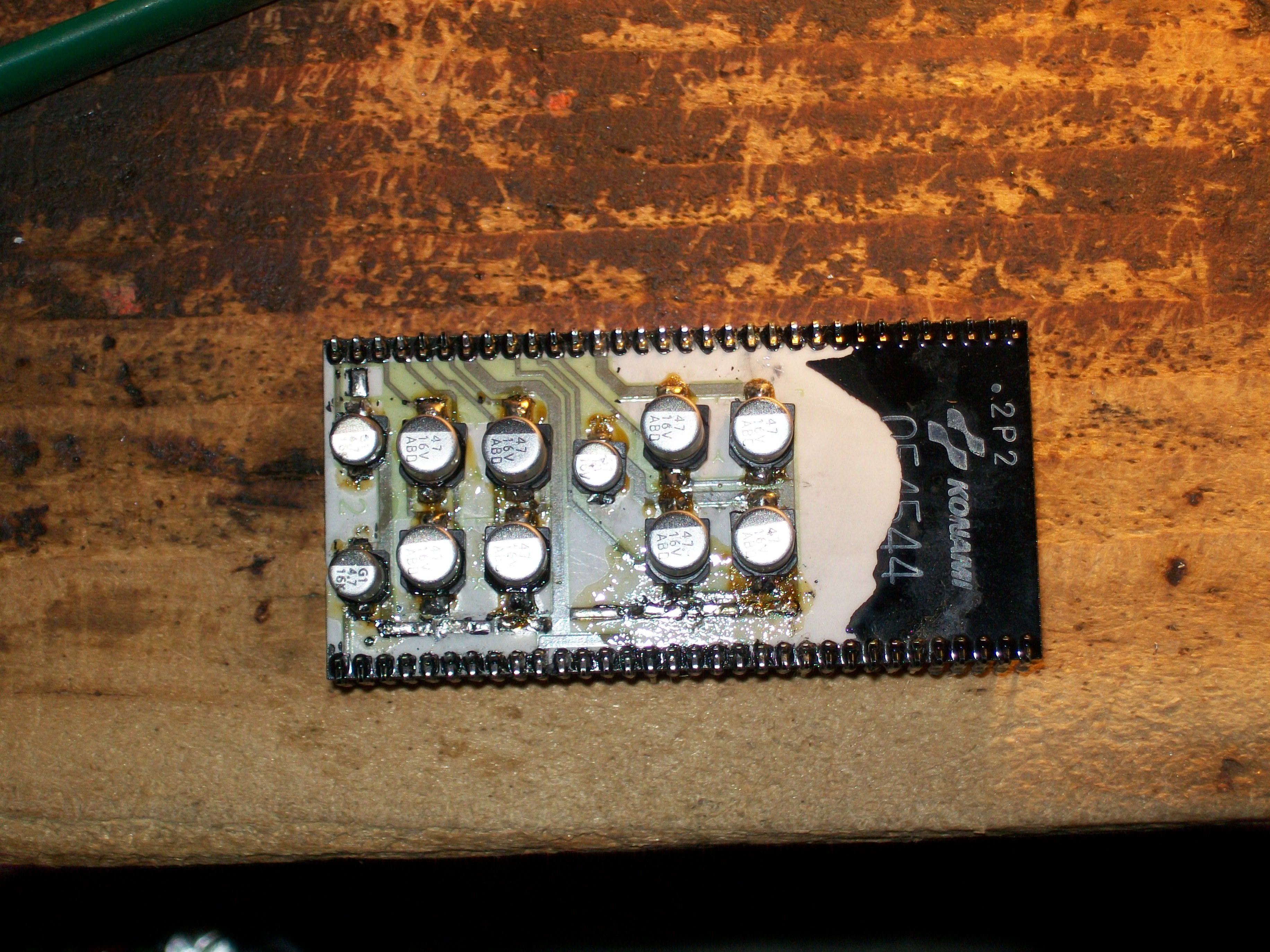
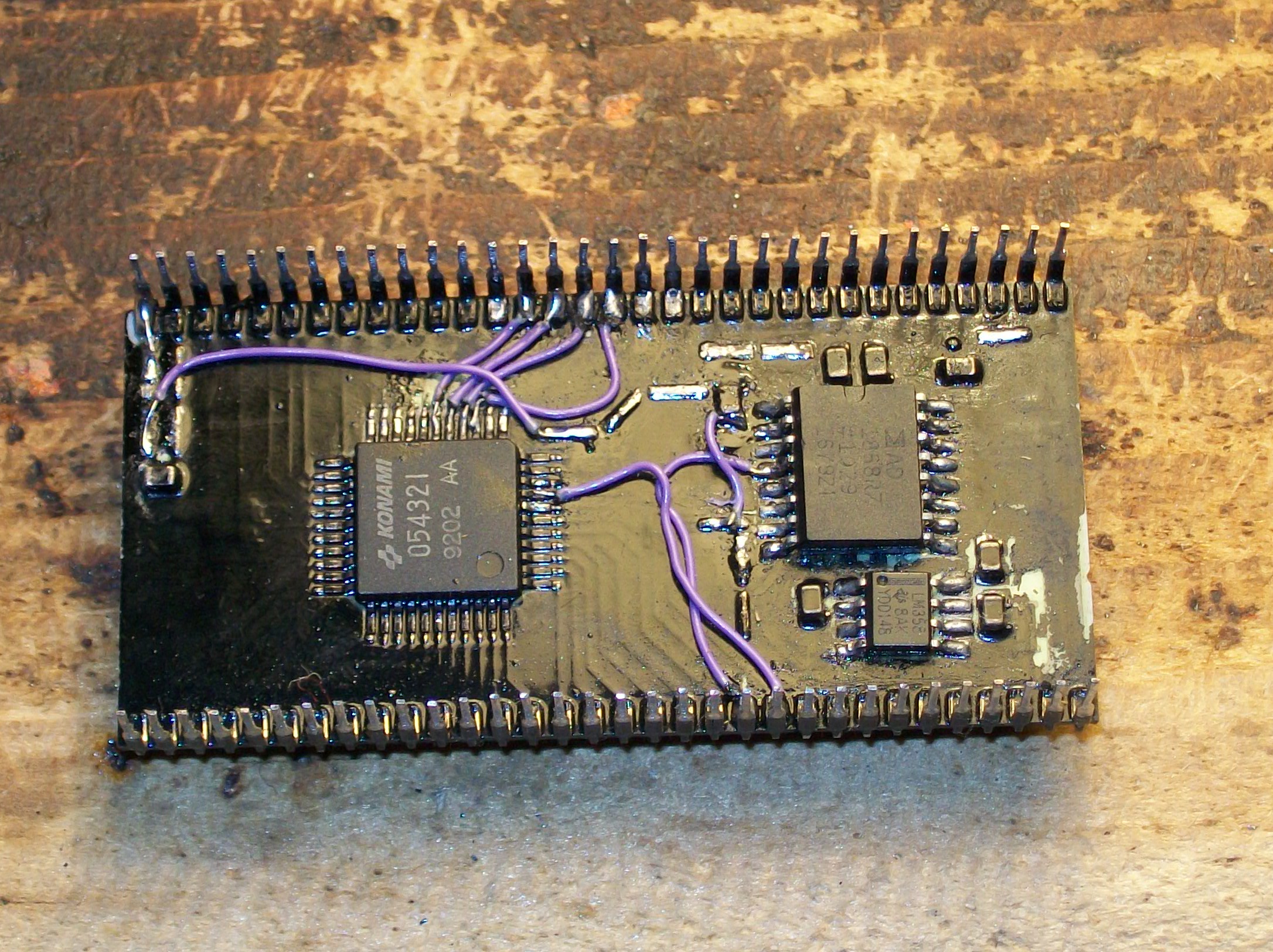
So, I removed the module from PCB and decided to fully service it:

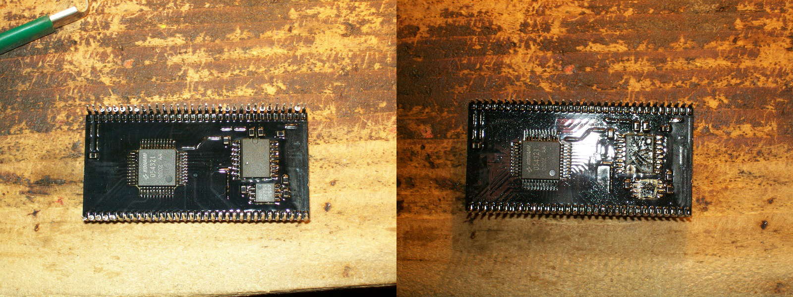
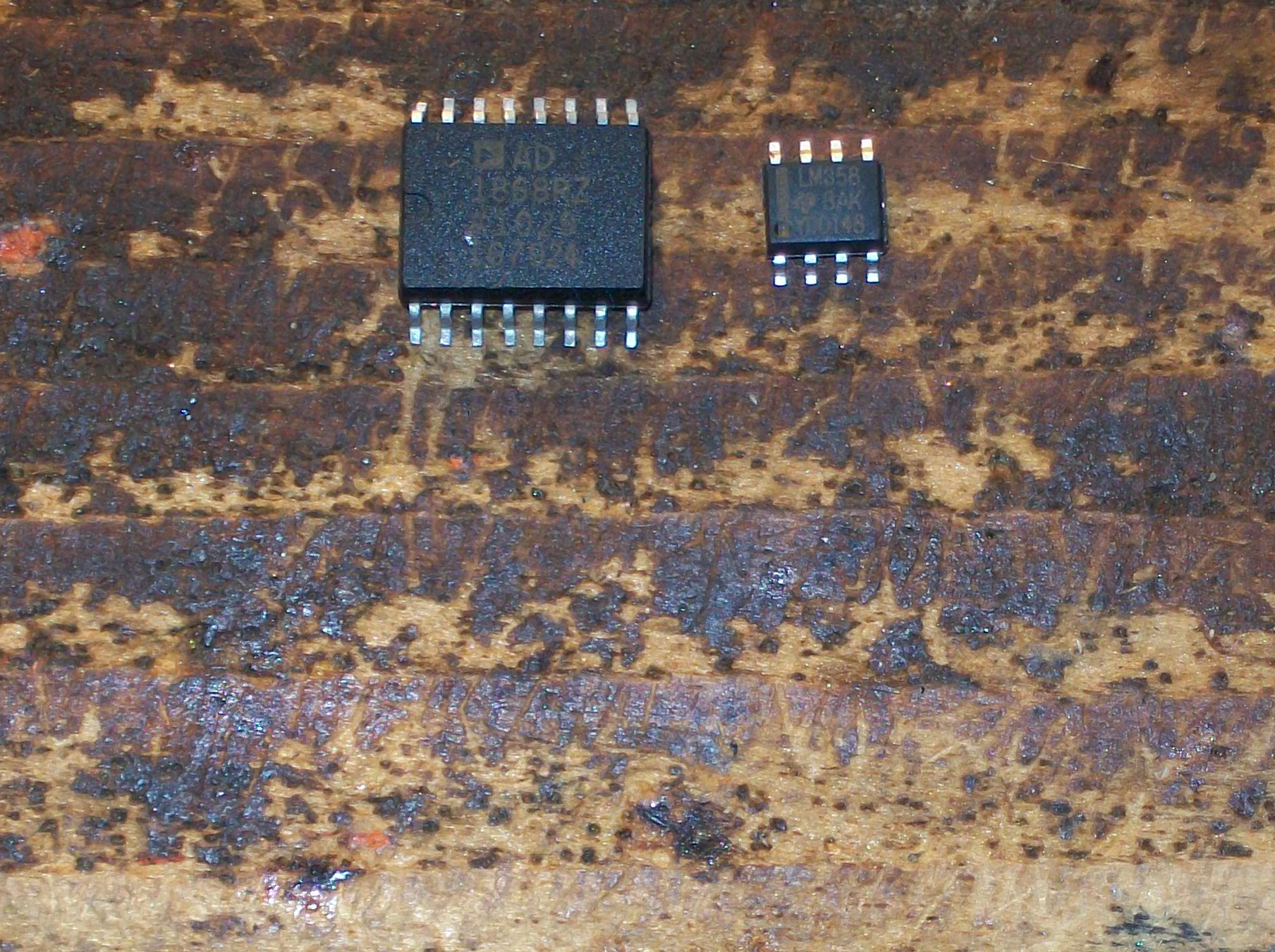
I replaced with new parts the 4558 OP-AMP (I used a compatible LM358) and the AD1868 DAC as well:

At same time I reinforced some poor connections  :

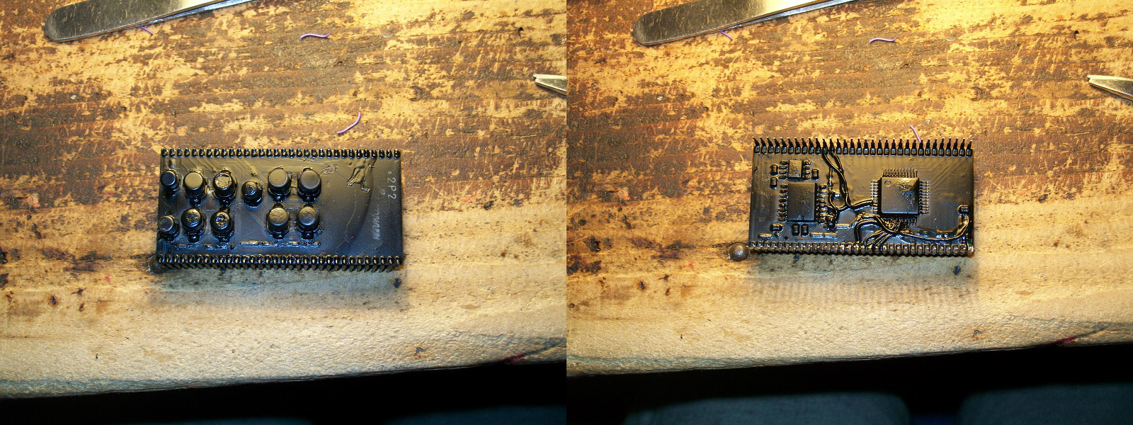
Lastly, as icing on the cake, I varnished with black laquer :

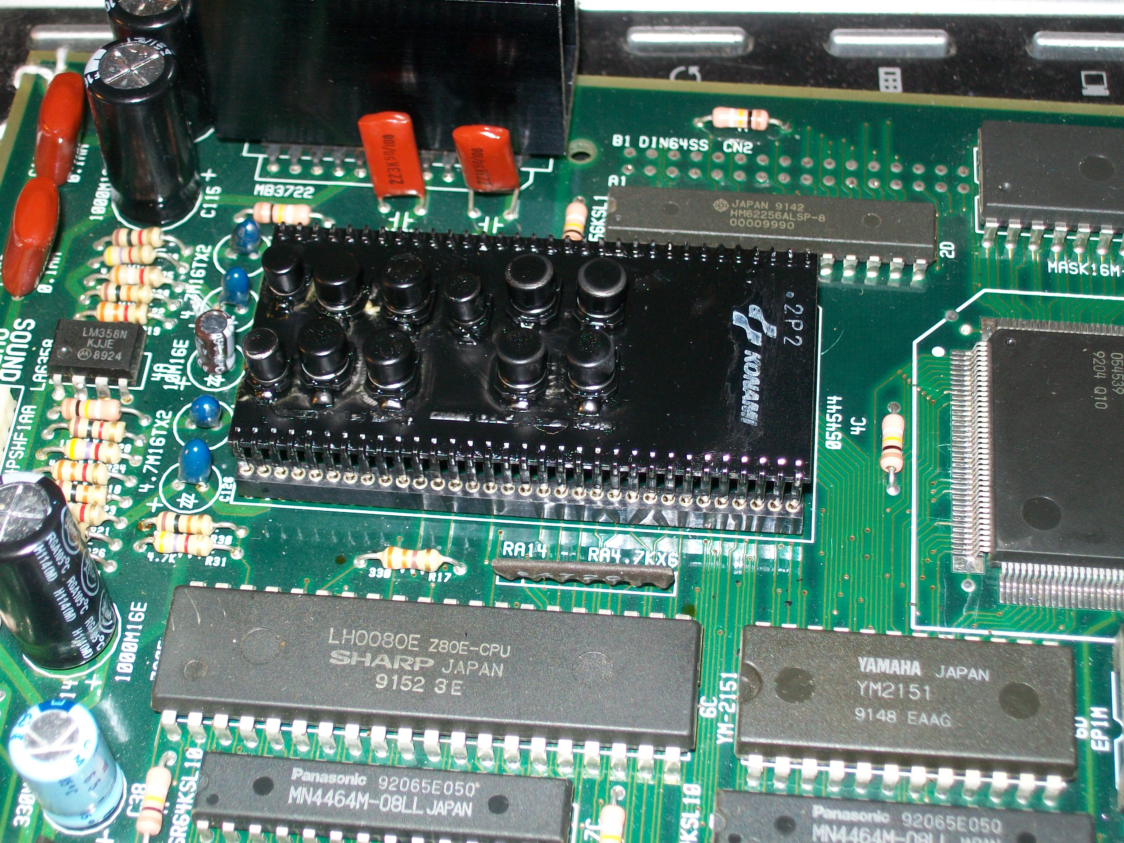
As always I do, I installed on PCB a couple of 1.778mm female round machine-tooled strips.This was the final result:

Time to test :

Job done.

P.S.

For the uninitiated, the ‘054544’ module has been reproduced, you can read more about on these threads:

https://forums.arcade-museum.com/showthread.php?t=386416

https://forums.arcade-museum.com/showthread.php?t=396393

 Posted by at 2:46 pm

Tatsujin Oh repair log #1

 PCB Repair Logs  Comments Off on Tatsujin Oh repair log #1
Mar 182017
 

Some months ago I received for a repair this Tatsujin Oh PCB (known outside Japan as Truxton II)

As you can see from the above picture, the custom ‘HK-1000’ (used for inputs) in front of JAMMA edge was missing but this was not the main problem, board won’t sync up:

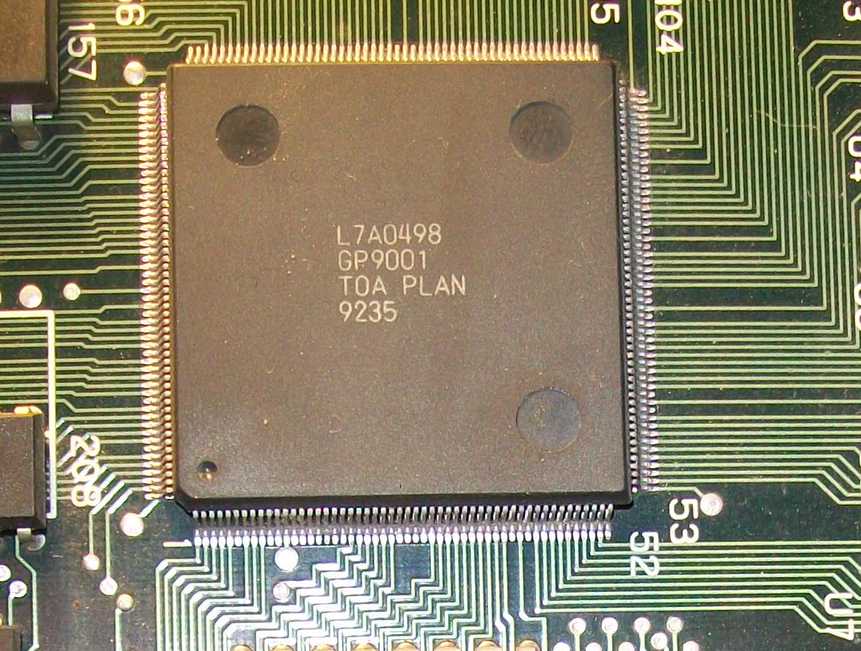
All the graphics and video timing signal (HSYNC, VSYNC, etc..) are generated by a large surface mounted ASIC (208 pins QFP package) marked ‘GP9001’:

You can find its pinout on page 32 of the Knuckle Bash schematics:

https://www.jammarcade.net/files/Schematics/Arcade/Knuckle%20Bash.pdf

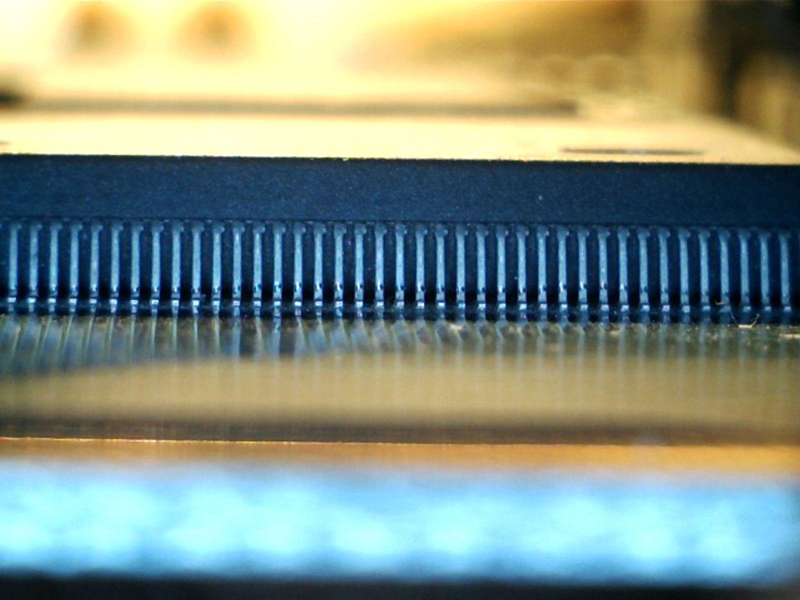
The IC was previously reworked by someone in a bad way, many pins were bridged together, flux residuals were not cleaned.So I decided to remove it :

and solder it again:

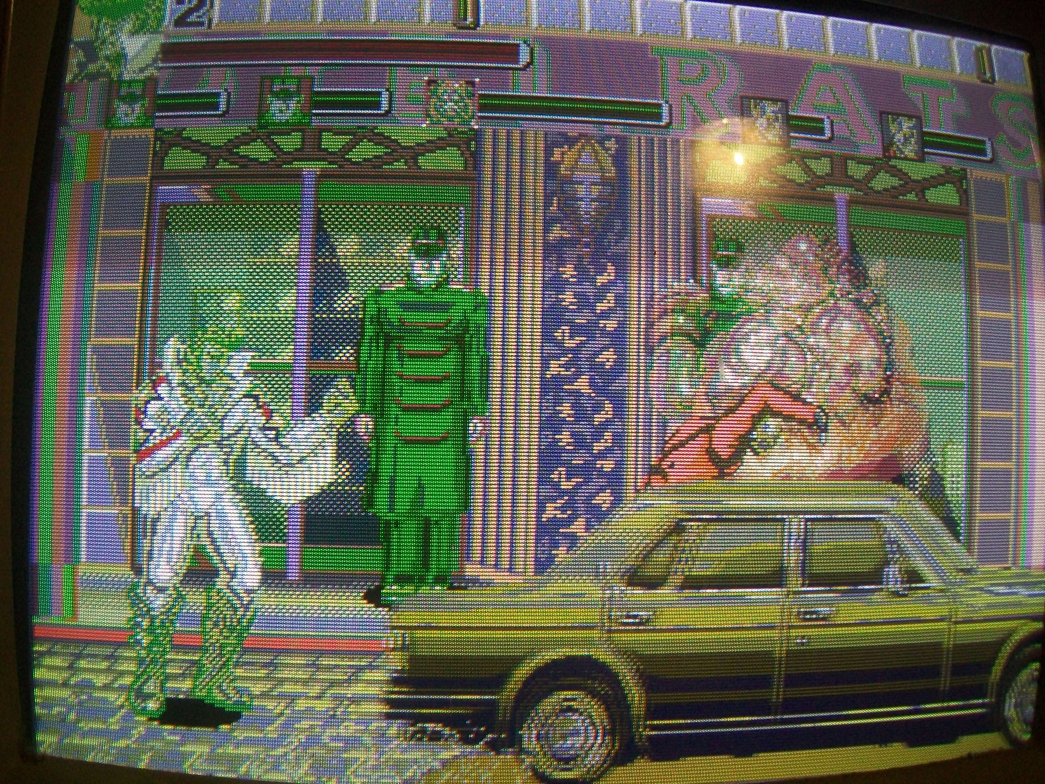
Happy with the result I powered up the board again and I was greeted but this static garbage screen:

Probing the main 68000 CPU revealed no activity on data bus.Doing a visual inspection of PCB I found a couple of severed traces on solderside just around the CPU area:

Patching them allowed the board to boot but, obviously, due the lack of the ‘HK-1000’, the game was stuck on a ‘TILT’ error message:

Input check in TEST mode reported ON most of them  :

Now some words on the ‘HK-1000’.As said, this custom handles all inputs and it’s has been adopted in later Toaplan PCBs.There are two revisions of it, the early one has a ceramic package and due this nature it’s very prone to damage and failure.This revision is used on Truxton II/Tatsujin Oh and FixEight:

The newer revision is more robust and it’s used on Ghox, Pipi & Bibis:

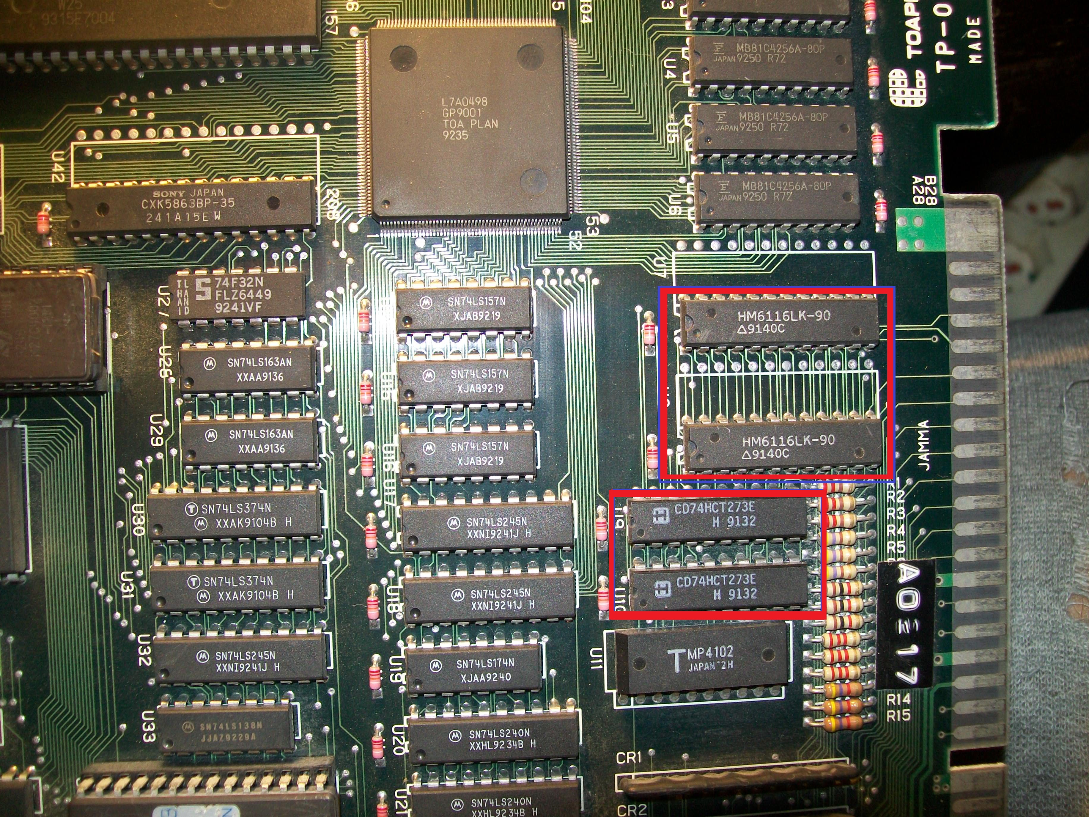
Back to repair, from available info it seems the functions of this custom can be reproduced using a couple of 74LS240  (actually the custom handles also the coin counters and lockout but we can omit it), this is not a suprise for me since a lot of previous Toaplan boards use same design with these TTLs (see for example Truxton, Wardner, Hellfire and other).Doing some tests with a single 74LS240 I was able to successfully map some inputs turning off the TILT error

This allowed me to enter in game :

Later, owner of the board installed the missing HK-1000 and confirmed the board was perfectly working after my repair:

P.S.

I’m currently drawing schematics for the replacement of the HK-1000 and I will post here my results.Stay tuned.

 Posted by at 11:12 pm

Truxton repair log #2

 PCB Repair Logs  Comments Off on Truxton repair log #2
Mar 182017
 

Some days ago I had this Truxton PCB on the bench:

Game had wrong colors on some background/foreground objects, like title screen

This part of graphics is generated by a ceramic PGA custom marked ‘NEC D65081R’ which addresses four 1Mbit MASK ROM and read/write data from/to four 62256 static RAMs:

Address bus is daisy-chained between the custom, the four MASK ROMs and the four RAMs, all was in order here.Custom receives data from MASK ROMs and transmits/receives to/from from RAMs on two different bus.When I went to check connections, I found no continuity between pin 17 (D5) of the RAM @18F and the custom.Here is where trace from pin of the RAM goes under the custom (picture taken with a USB microscope)

Infact, if I pressed the custom in this corner, the fault went away.I simply reflowed this dry joint and all came back to normality.

 Posted by at 6:44 pm