64th Street – A Detective Story repair log #1

 PCB Repair Logs, Repair Logs  Comments Off on 64th Street – A Detective Story repair log #1
Oct 292018
 

This PCB from my collection had a subtle problem after some minutes of being turned on and with voltages more than 5.1V

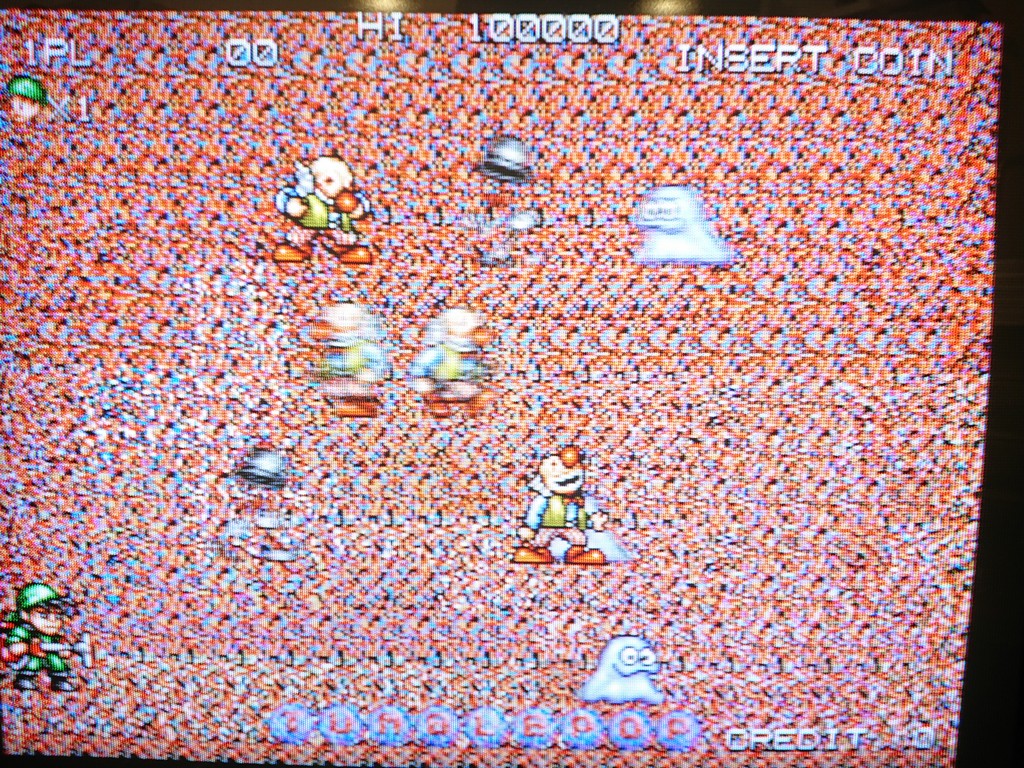
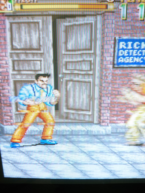
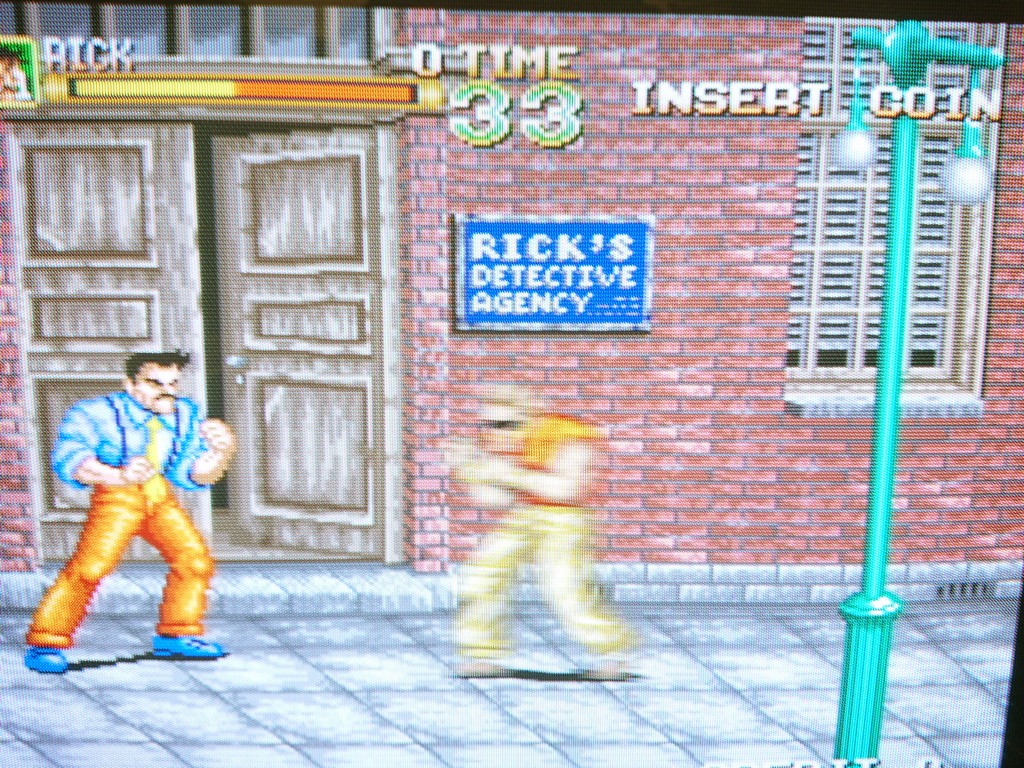
Some lines of the sprites started to be shifted toward the left


If I lowered the voltage to exactly 5V the sprites were good.

Being a perfectionist I started to find the culprint and eventually I found the circuit involved in the problem.

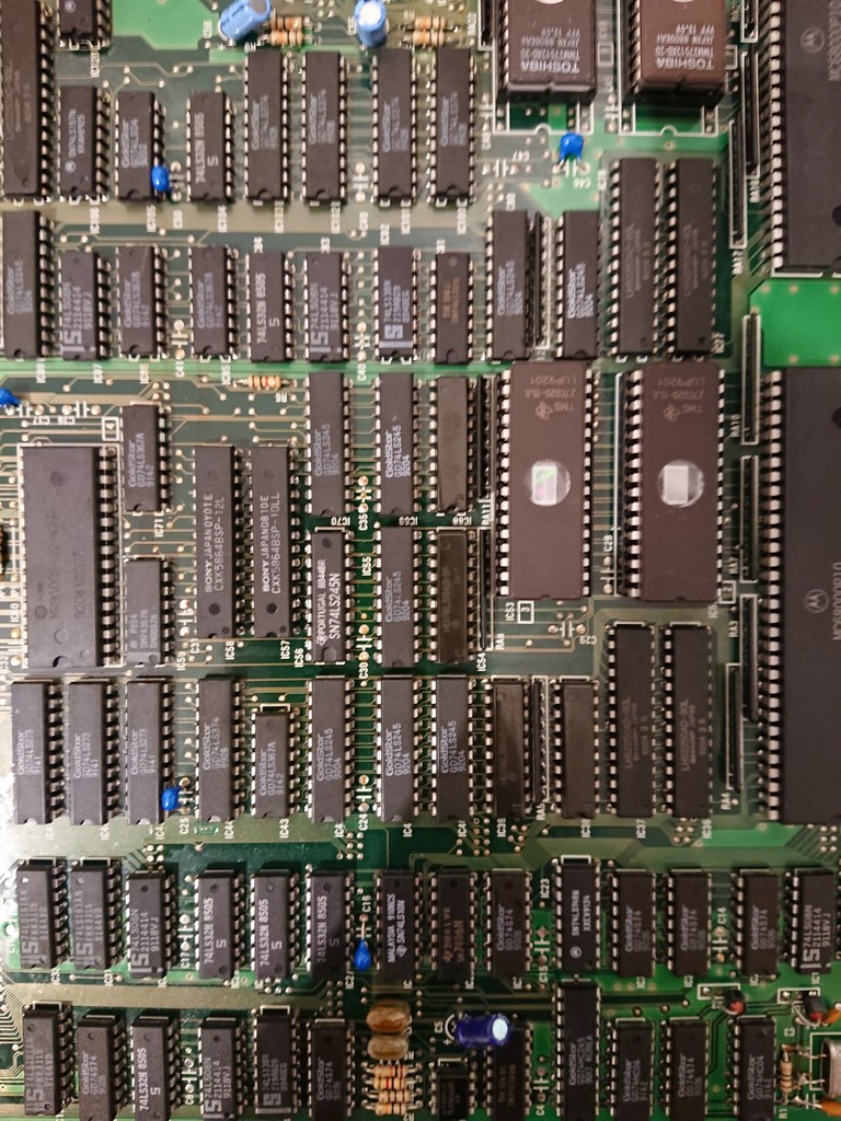
If I put the oscilloscope tip on pin 2 of 74LS365@IC55, the problem got worse, more lines were shifted to the left.

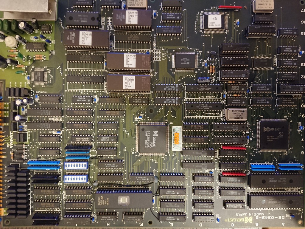
The chip was good so I changed also all the components which were in the chain, a 74LS245@IC56 and a couple of rams @IC57 and IC58

It must be said that all these components had healthy a good looking signals on the oscilloscope and they were tested good out of circuit but I decided nevertheless to change them with other brands to rule out every possibility

Still same issues after some minutes powered on

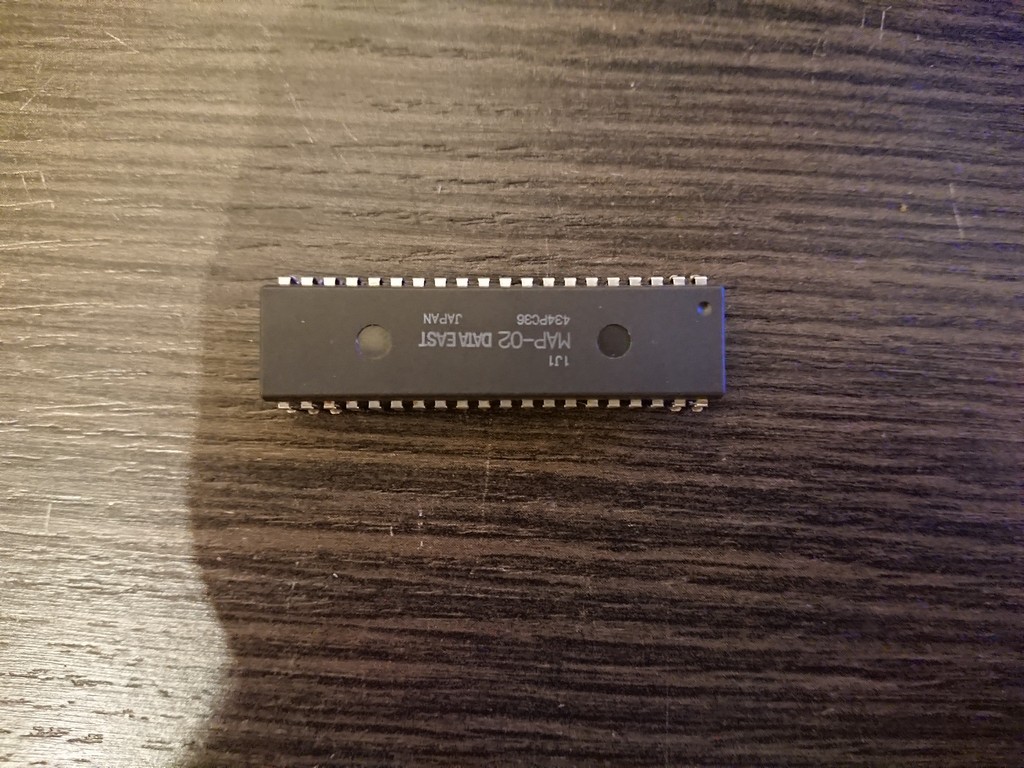
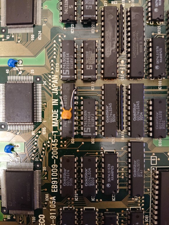
At this time I really thought it was either the sprite maskrom or the custom chip which was the source signal of pin 2 of 74ls365 until I noticed that the same signal was also connected to pin8 74LS273@IC94 which was pretty far from the other chips in the chain.

I decided to make a piggyback with a good chip and the problem desappeared completely at all voltages.

I changed it without further checking and still the problem was there!

With the tip of the oscilloscope I touched pin 8 and the problem disappeared immediately.

The oscilloscope probe has some capacitance which delayed somewhat the signal and fixed the problem.

So I installed a ceramic cap between GND and pin 8 and the problem was 100%


I think that this board had always a timing issue that no one addressed and preferred to run it with exactly 5V

Pacland repair log #2

 PCB Repair Logs, Repair Logs  Comments Off on Pacland repair log #2
Oct 282018
 

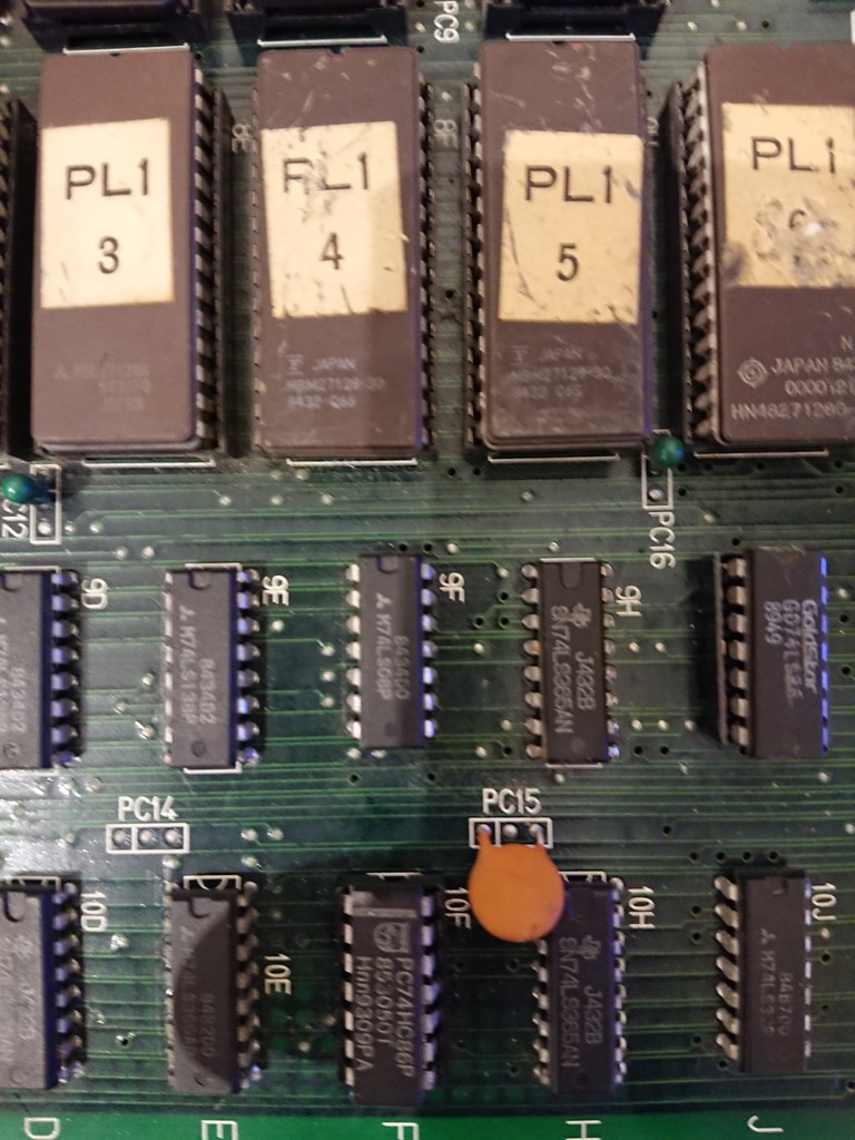
Received a pacland board for a repair which was stuck with a  0 2 0 error at boot.

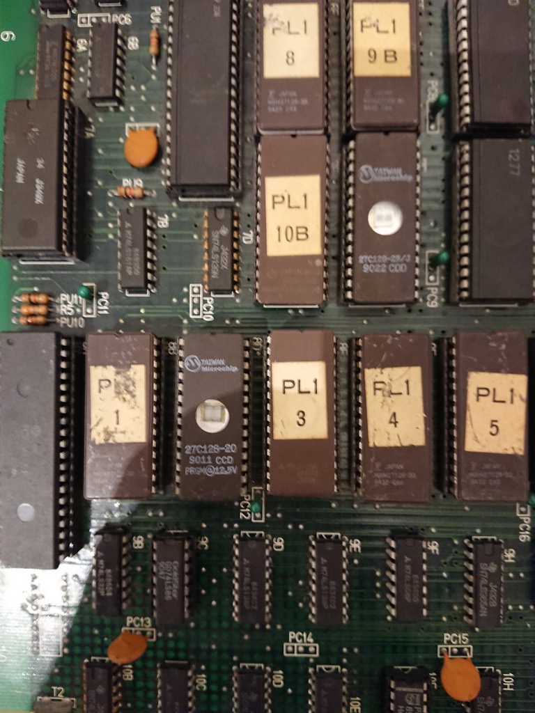
Normally the middle digit means it’s an program rom error and infact the second prg rom @8D had no sticker  and I immediately checked it.


Romident showed it was a Pacland midway rom, but the other prg roms belonged to the japanes new version.

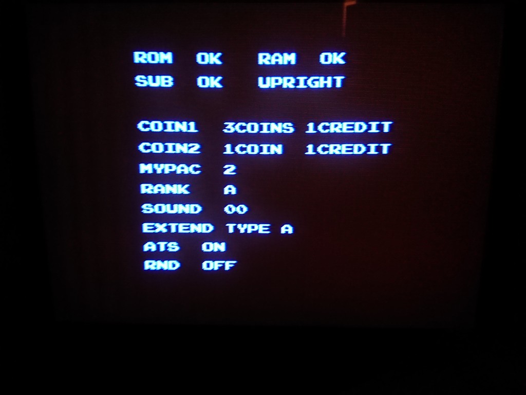
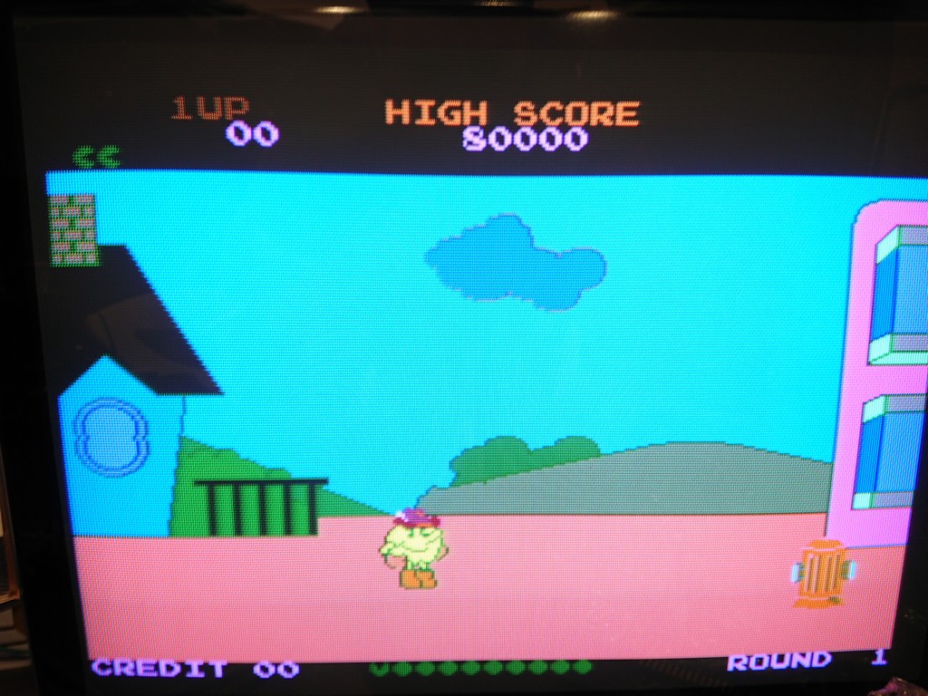
After burning the correct 2nd rom from the jap set I was welcomed with this screen which is the service one.

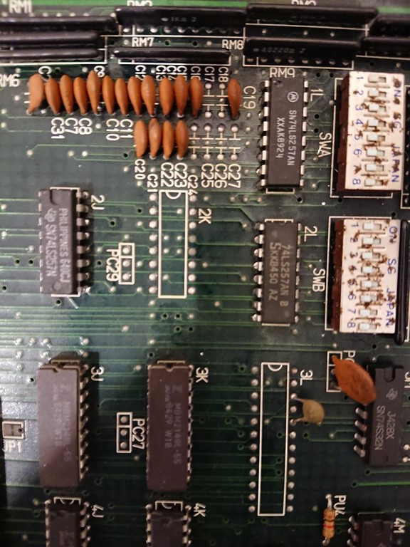
The dipswitches were all set OFF and after verifying they were working correctly I decided to change all the FUJITSU 74LS257 near them which had dead outputs infact.

In the end all the Fujistsu chips has been changed because faulty: @1L, 2L and 2J!


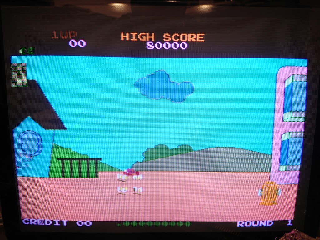
With good ones changed the game finally booted but the palette was very tinted and the sprites were corrupted:


Verifying the sprites roms 8,9,10 and 11 these were a mess of different revisions, so using a broken pacland I put the matching roms from the new japanese set

Still the sprites were corrupted and eventually I found a bad 74ls86 ( again Fujitsu) @10F


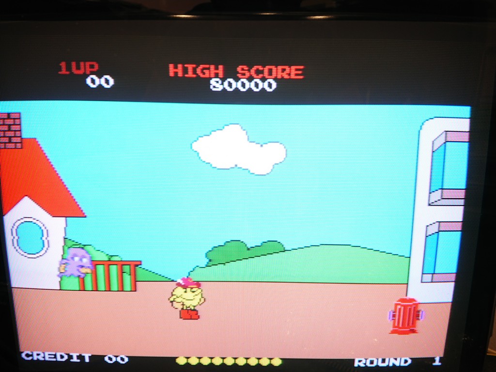
With good one installed I got finally good sprites but still the palette was tinted:


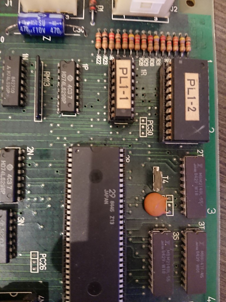
I proceeded on the colour prom section and found that the chip PL1-2 had some outputs dead


Using one from another Pacland board fixed the game 100%


Bucky O’ Hare repair log #4

 PCB Repair Logs  Comments Off on Bucky O’ Hare repair log #4
Oct 212018
 

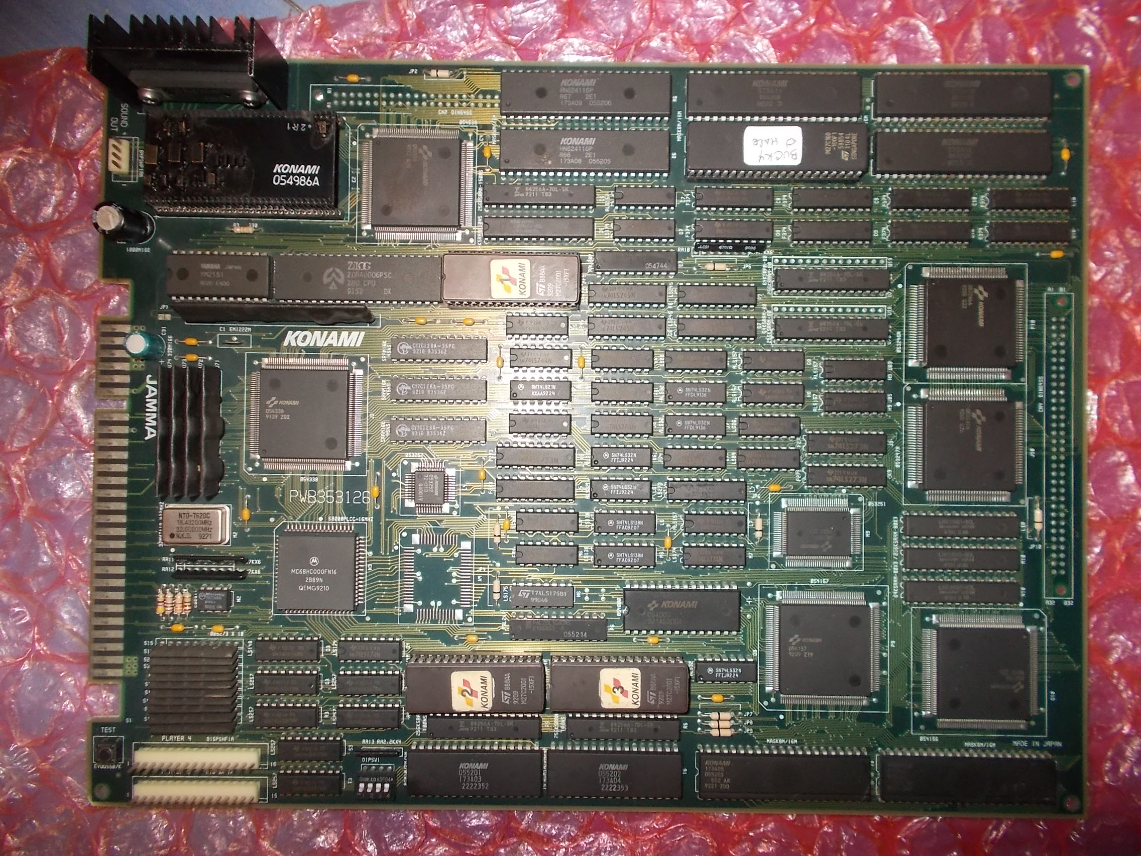
Received from Greece this Bucky O’ Hare PCB :

Owner told me the PCB developed some sound issue so he wanted the ‘054986A’ audio module replaced with a repro of mine.This is what I did but it didn’t cure the problem, the sound samples were corrupted and some of them missing too :

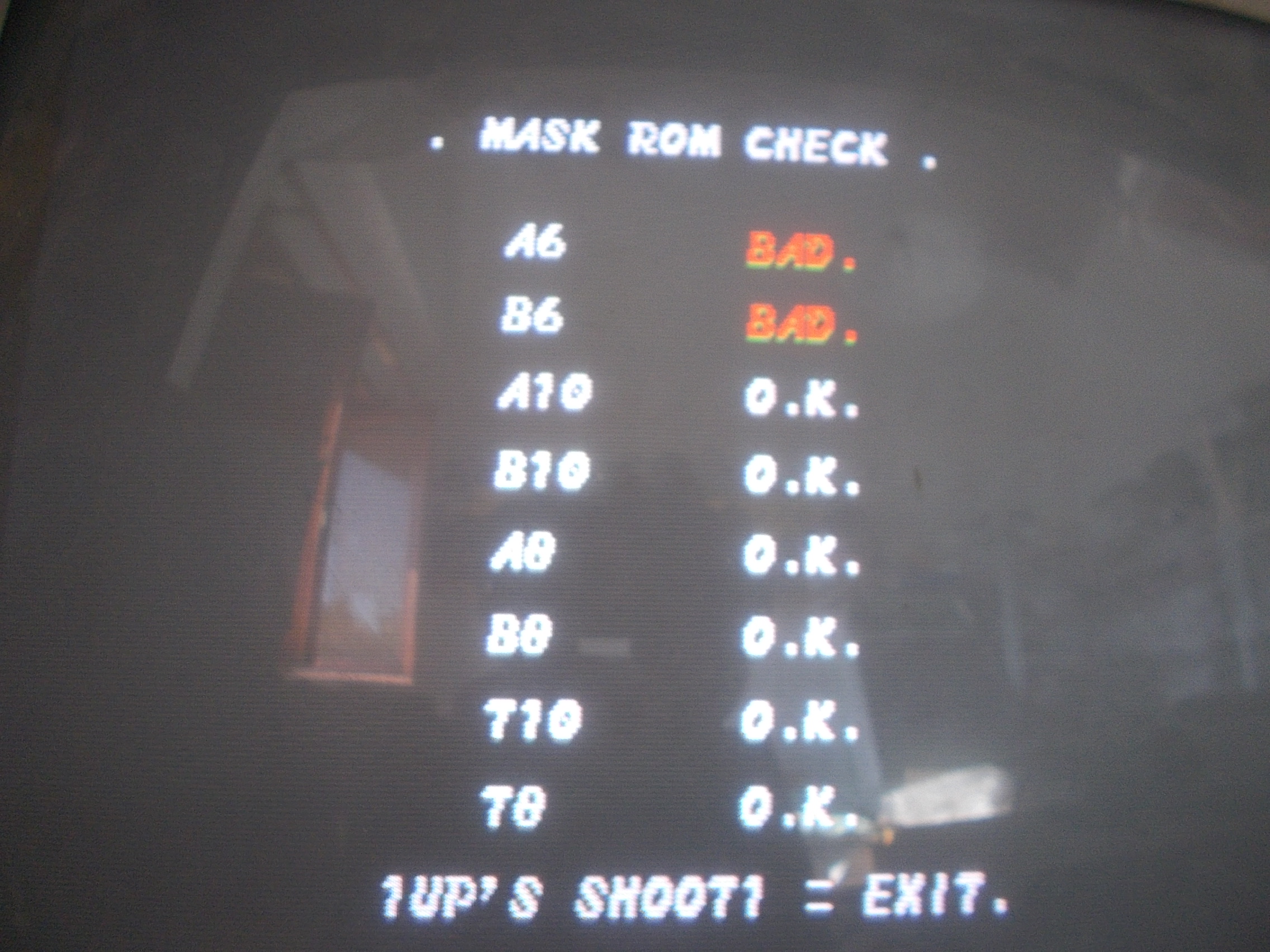
The MASK ROMs test reported two bad devices @A6 and B6:

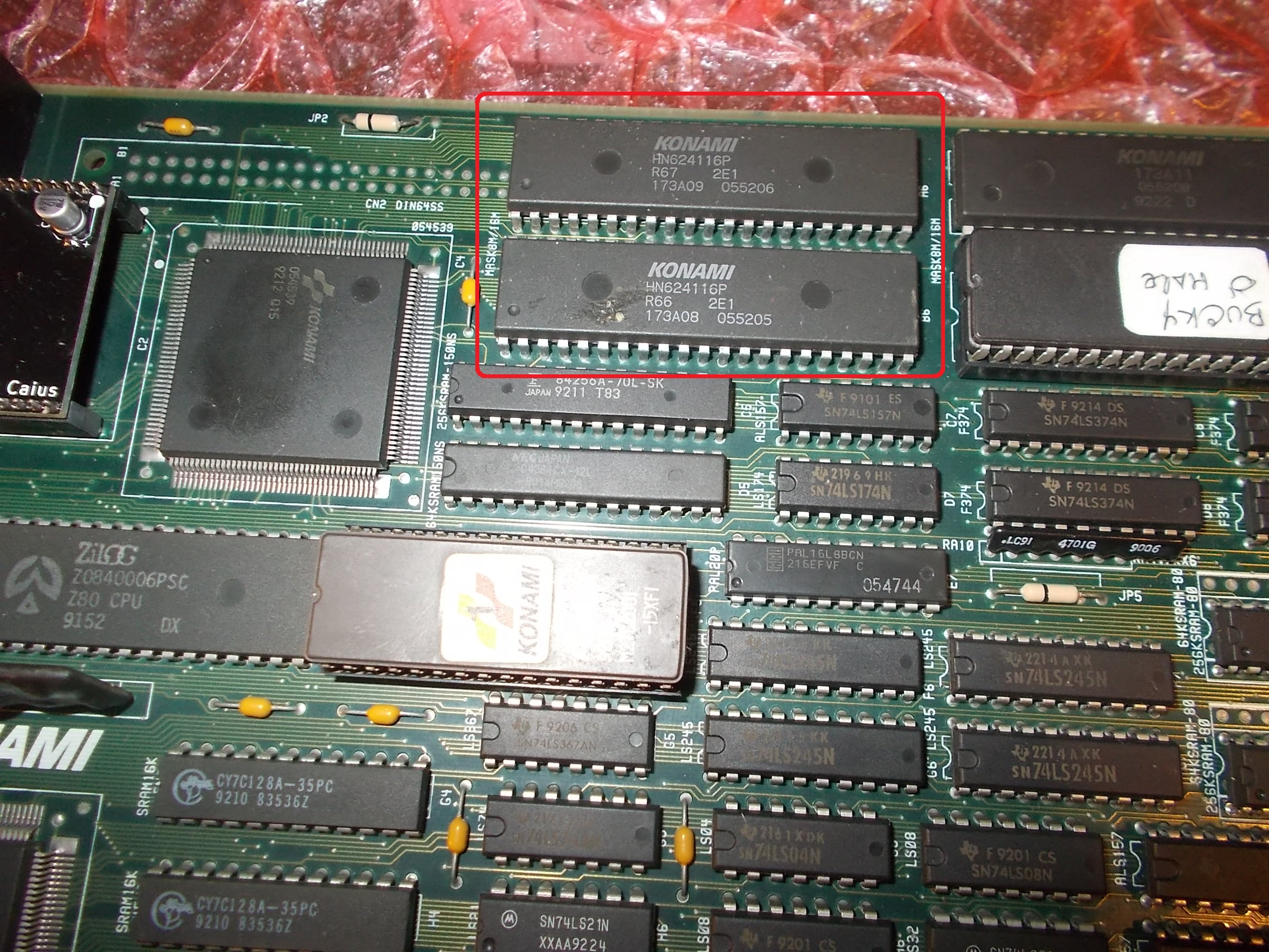
They are the 16Mbit MASK ROMs that stores PCM samples:

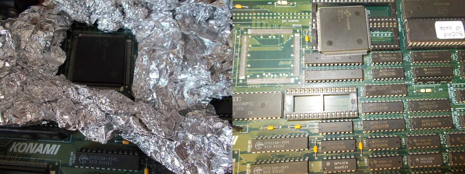
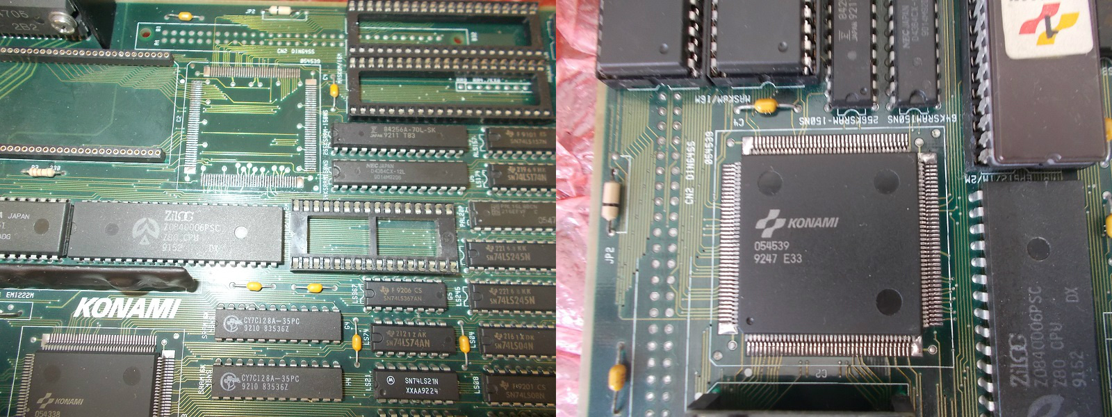
This wass unlikely but possible so I removed and read them resulting in good dumps.At this point there was nothing else to check, the PCM samples data are processed by the near custom ASIC marked ‘054539’ which was most likely faulty.I prepared the board and desoldered the chip with hot air :

Then cleaned the area and soldered the spare taken from a donor board:

Sound was back clear and complete again.End of repair.

 Posted by at 7:21 pm
Oct 142018
 

Some time ago I bought an untested Sega Dreamcast console (with no video cable or other accessories included) with the intention someday to replace the optical drive with a GDEMU :

I was lucky because it was a japanese HKT-3000 model with VA1 motherboard and 3.3V GD-ROM assembly so perfectly compatible with Deunan’s GDEMU :


Some days ago I finally got an A/V cable so it was time to power up the console for the first time.With my disappoint all I got was a disturbed video signal, nothing came up on the screen:

I opened the console and did an inspection :

First of all I looked at PSU and immediately my attention was caught by the big 100uF 200V electrolytic capacitor @C3 which was clearly ‘bulging’ (you can see how top of the metal can is dilated)

This capacitor has a very important function as it filters (suppressing the ripple) the AC source that then get transformed by the rest of the PSU circuit.It measured little more than 7000 pF (0,007 µF) when tested out-of-circuit showing no ESR value at all :

I replaced it with a low-ESR one and checked in circuit the ESR of the other electrolytic capacitors, they were all good:

I powered up the console and I was delighted by the startup intro animation (sorry for B/W picture but my Philips CM8833-II monitor doesn’t accept NTSC signals)

Now waiting for a joypad and then time to play with wonderful Deunan’s GDEMU ODE!

 Posted by at 10:08 am

Silent Dragon repair log #2

 PCB Repair Logs  Comments Off on Silent Dragon repair log #2
Oct 122018
 

Received today this Silent Dragon PCB (a not so well known beat ’em up manufactured by Taito) that I bought as faulty :

According to the seller board played fine but sound was absent.He was right:

Some one tried to replace invain the audio amplifier:

A quick check with my audio probe revealed the issue had a digital and not analog cause.So I went to probe the Z80 audio CPU and found its /INT line always asserted:

This means a maskable interrupt to the CPU was triggered by an external I/O device.This causes execution to jump to a specific interrupt vector (which is some code at a fixed location).Execution  can then continue after the interrupt vector routine has finished but in my case the /INT line was LOW all the time so the CPU was not properly running.

A further check  revealed pin 21 /RD and pin 22 /WR were shorted each other:

I turned the board over and did a visual inspection on solder side, my attention was caught by this particular:

Under a microscope:

A solder bridge was shorting two vias connected not only to pin 21 and 22 of the Z80 but also to two pins of the ‘TC0140SYT’ ASIC (the sound and interrupt controller)

I removed the bridge with my iron tip and sound was back.Job done

 Posted by at 5:24 pm