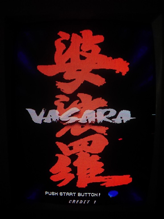
Some months bought for my collection Vasara and Vasara 2 in bundle from an american guy.
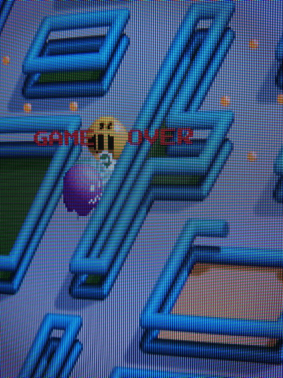
From the beginning Inoticed that Vasara had very dimmed colours and required to adjust monitor constrast to the maximum in comparison to Vasara 2.
Since I was not familiar with this system I thought it was due to the motherboard revision which is earlier on Vasara ( and there is a factory mod to make it compatible)
After some months I decided to check on internet if someone had a similar problem and I found mentioned on system11 blog about Cave CV1000 colour problems.
According to him it’s a very common problems on SSV games and I found also mentioned on japanese blog sites afterward.
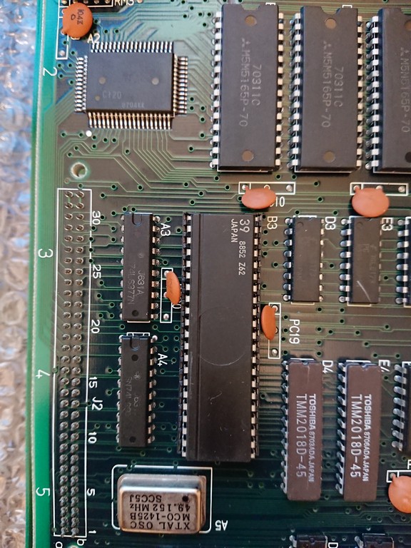
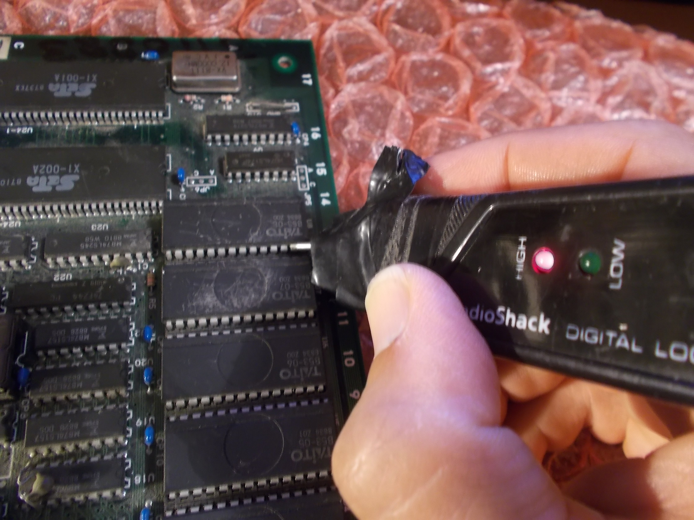
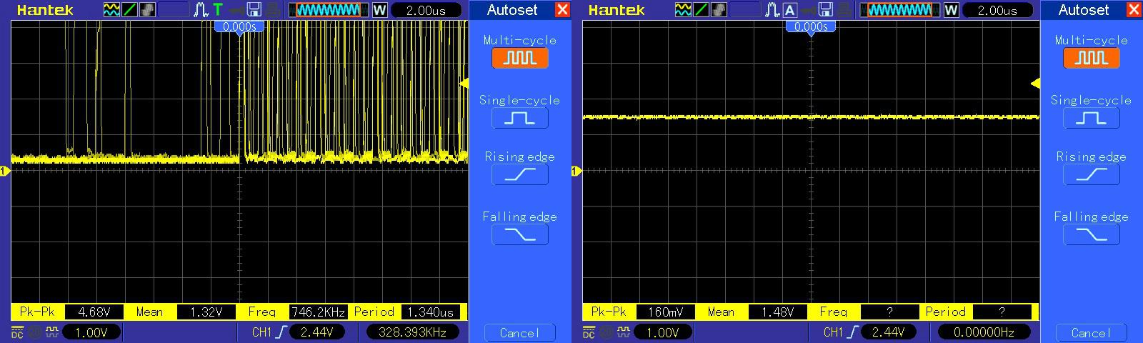
I checked with the oscilloscope the signals coming out from the 4 2sc1674 transistors ( RGB ans SYNC) and indeed all of them very about 2volts, same intensity of the inputs.
Signals in Vasara 2 in comparison were about 3,5V
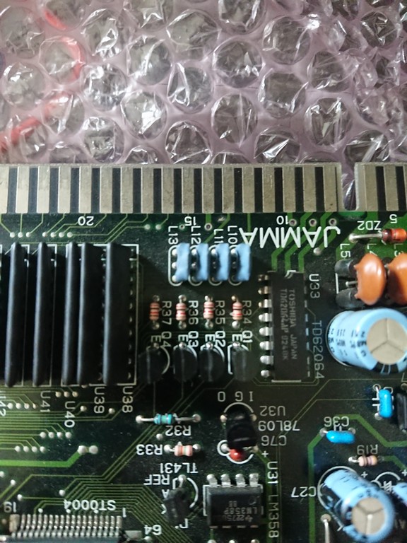
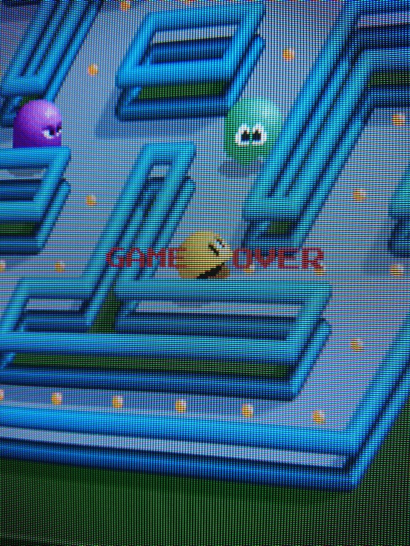
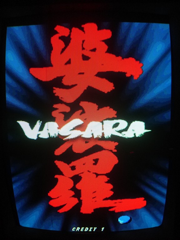
I decided to change all of them and indeed it fixed the dimmed colours which are now very bright and crisp
What I find really curious is that all of them went faulty, I think probably the transistors choosen by Seta are not correct for this kind of load.
Maybe someone with a good electronic background can shed a light