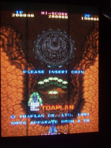
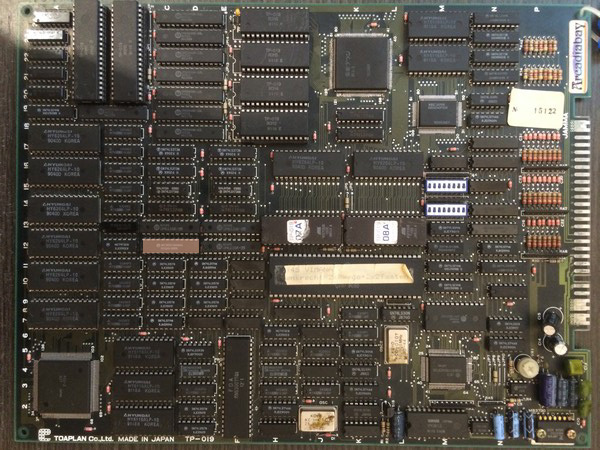
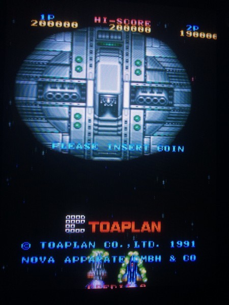
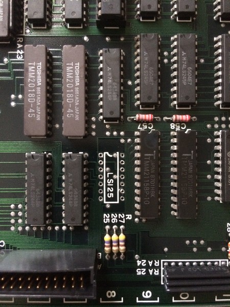
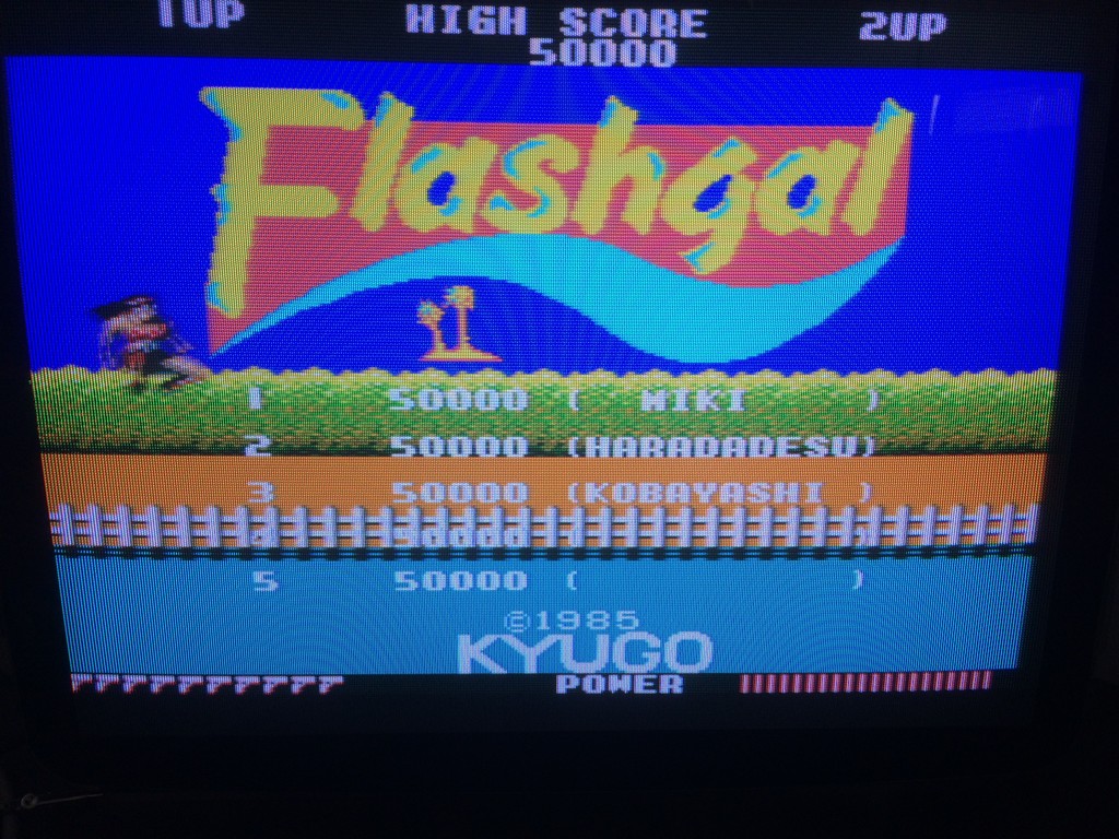
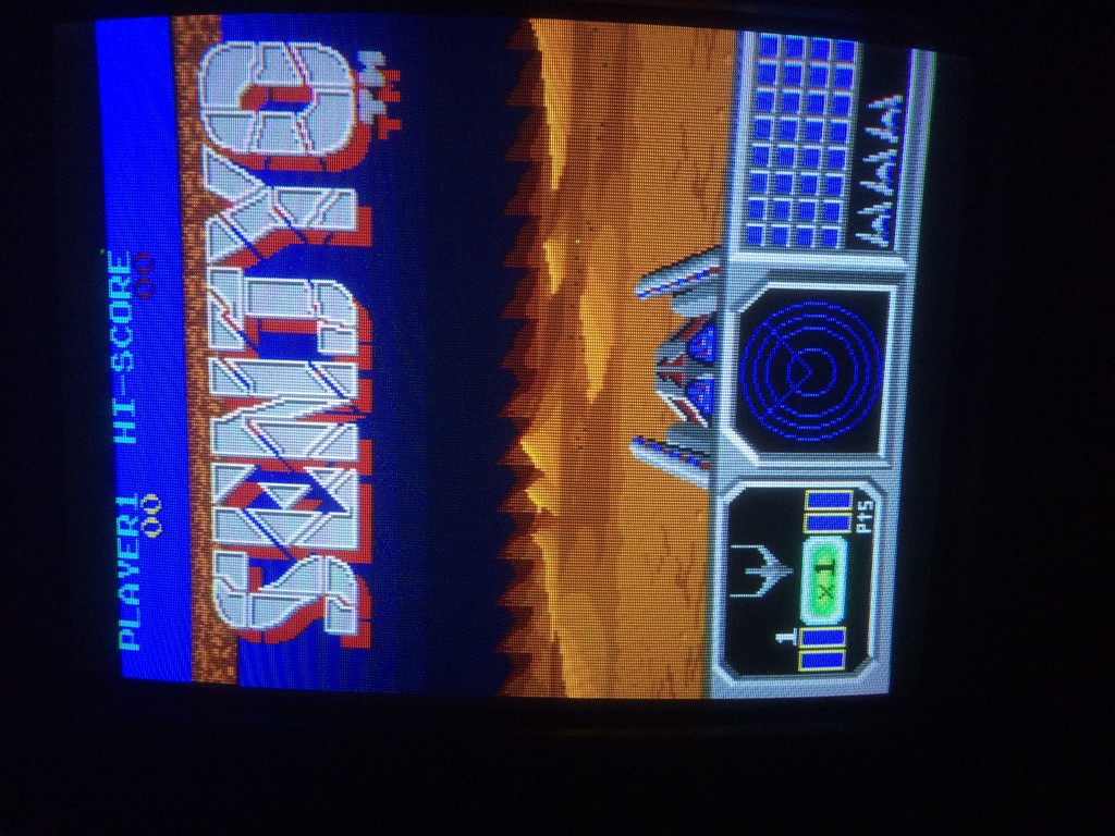
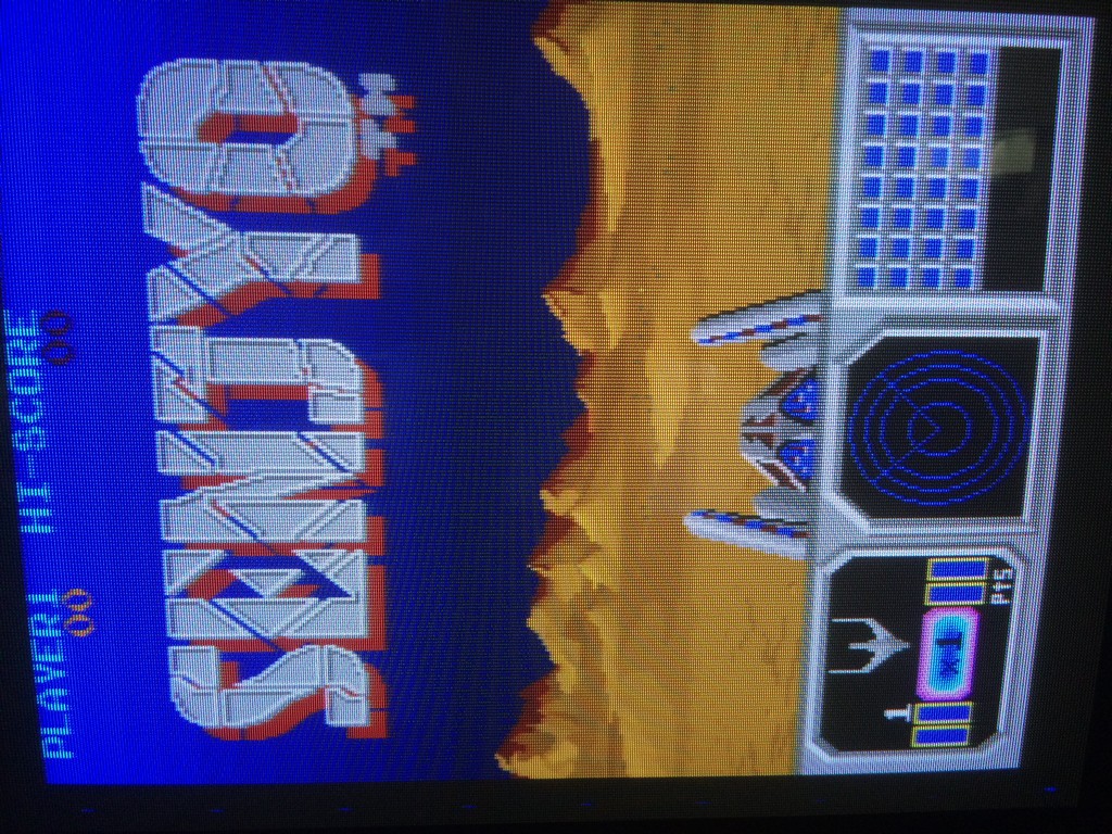
I bought this game for my collection declared perfectly working.
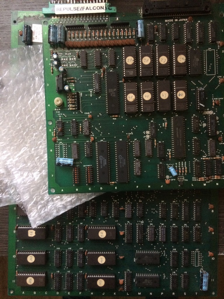
Flashgal runs on the very same pcb of other two games developed by Kyugo which are 99 Last War and Legend.
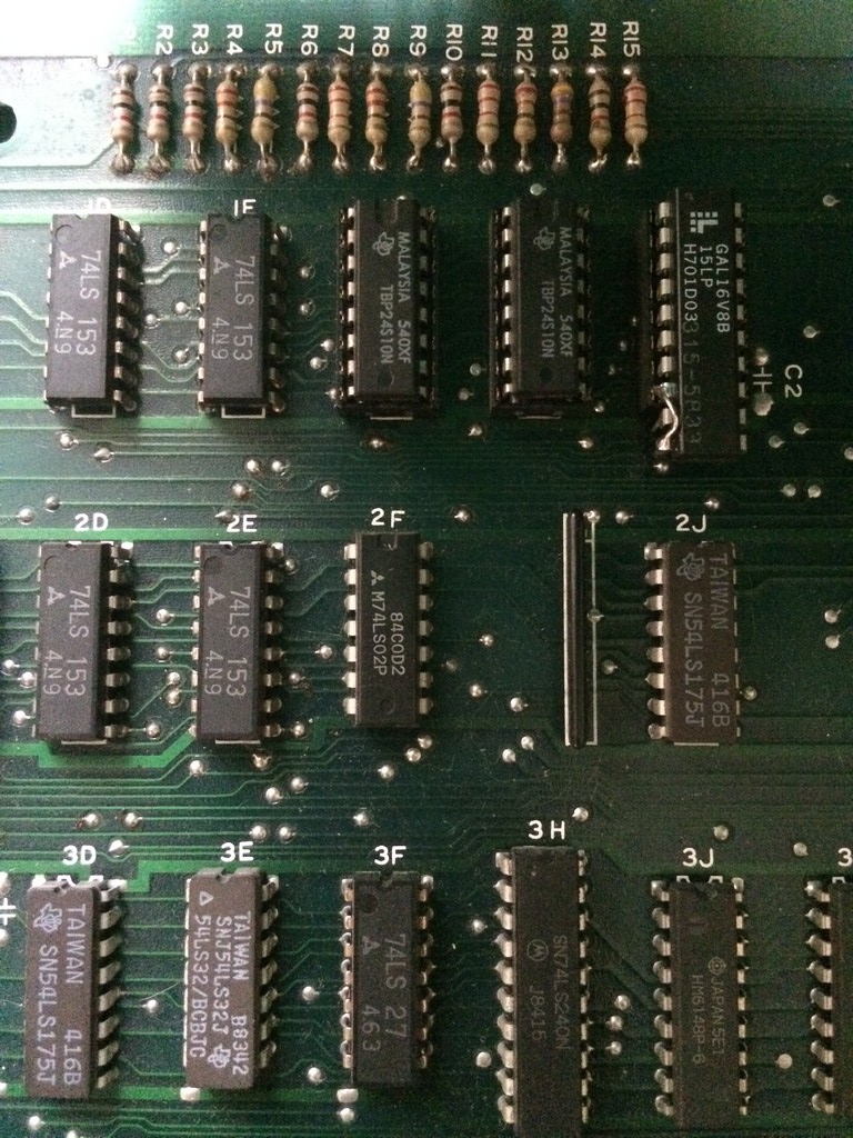
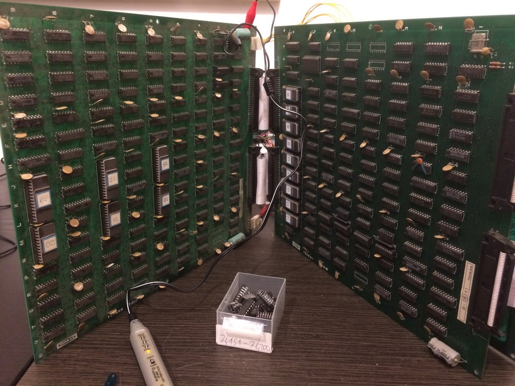
On the bottom pcb it is silkscreened CVG-48C which is very similar to the codes used by ORCA on their hardware

Anyway it seems that in these days I am very unlucky because the game once fired up had a sync problem

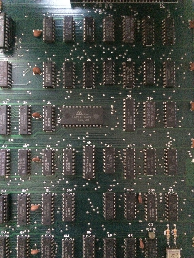
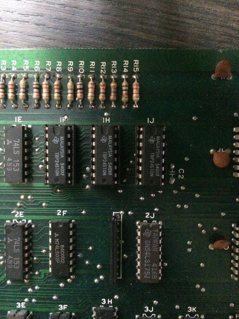
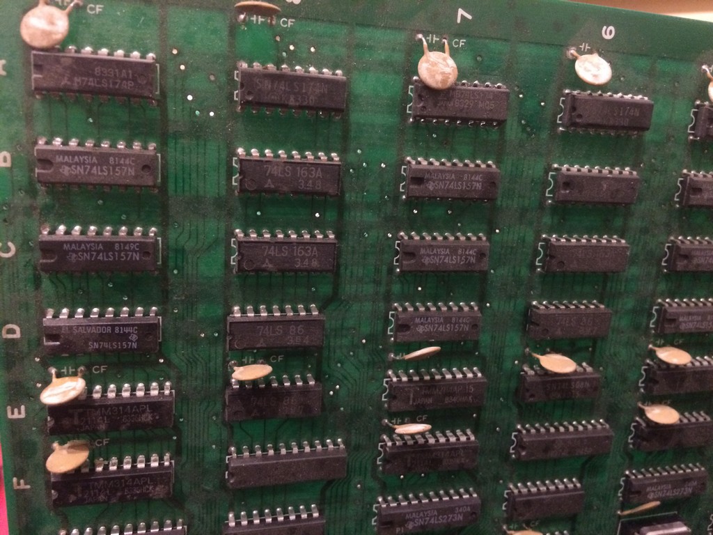
Tracing back from the SYNC pin I came to a 74LS08@2P

With the frequency counter I got very unstable readings so I proceeded to piggyback it with a good 74LS08 which restored the sync.
After changing it, it tested good out of circuit, yet with the new TTL in place I got a stable sync….
The screen looked very reddish so there was obiviously a palette problem

I checked the palette rams and they were all good so I dumped the colour proms until I found the RED component one @1J which didn’t match anything in MAME.

The prom is an 82s129 and it is almost impossible to find an empty replacement these days.
Therefore I went again for the Bprom to Gal replacement already used last year in another repair log:
Mad Gear repair log
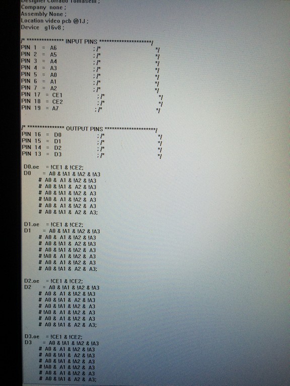
Since the prom was the very same type I replaced for Mad Gear, I converted the prom file to the PLD equations using Elgen tool U2pa and I reused the same pin configurations which fits nicely without any major hardware mod except a jumper wire to connect GND to the correct pin on the GAL

I tested the the game but I noticed something strange:

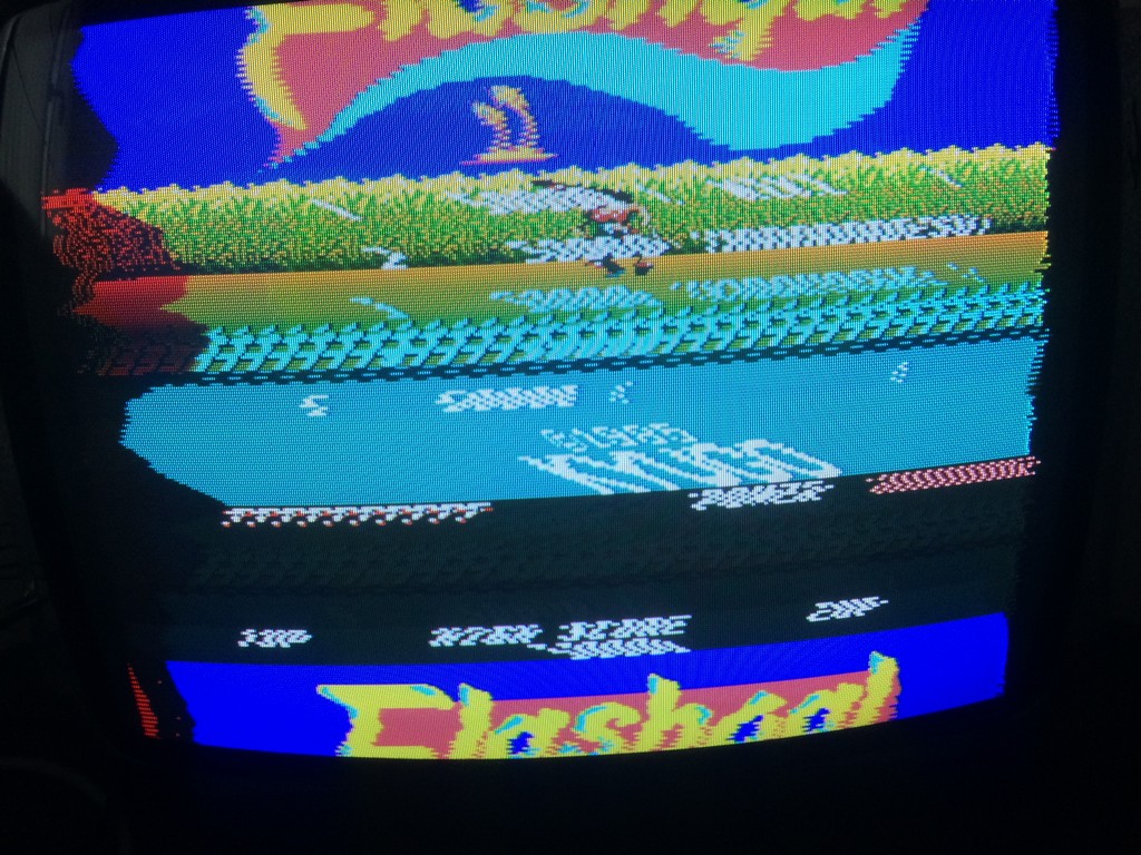
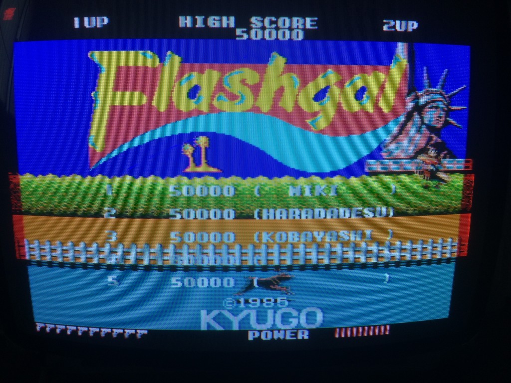
The colours were right but there were glitches on the left and right borders and also a flickering red component across all the screen (which cannot be seen on the static image offcourse)
At first I thought it was an access time problem with my GAL , therefore I burned the fastest one I had but no luck.
I tested directly the signals of the PROMS and found out that the CE pins were not tight to GND but were controlled by another ttl.
Soon it became clear why it didn’t work: the GAL was sending datas out of sync therefore producing artifacts.
Since I am not a programmer I asked to Elgen and Caius (who asked to Porchy) an advice how to replicate on the PLD a tristate behaviour.
All of them were very kind and in few minutes they informed me how tristate works on PLD equations
I added the needed modifications to my PLD equations by declaring each data pin enabled when pins CE1 and CE2 were low.

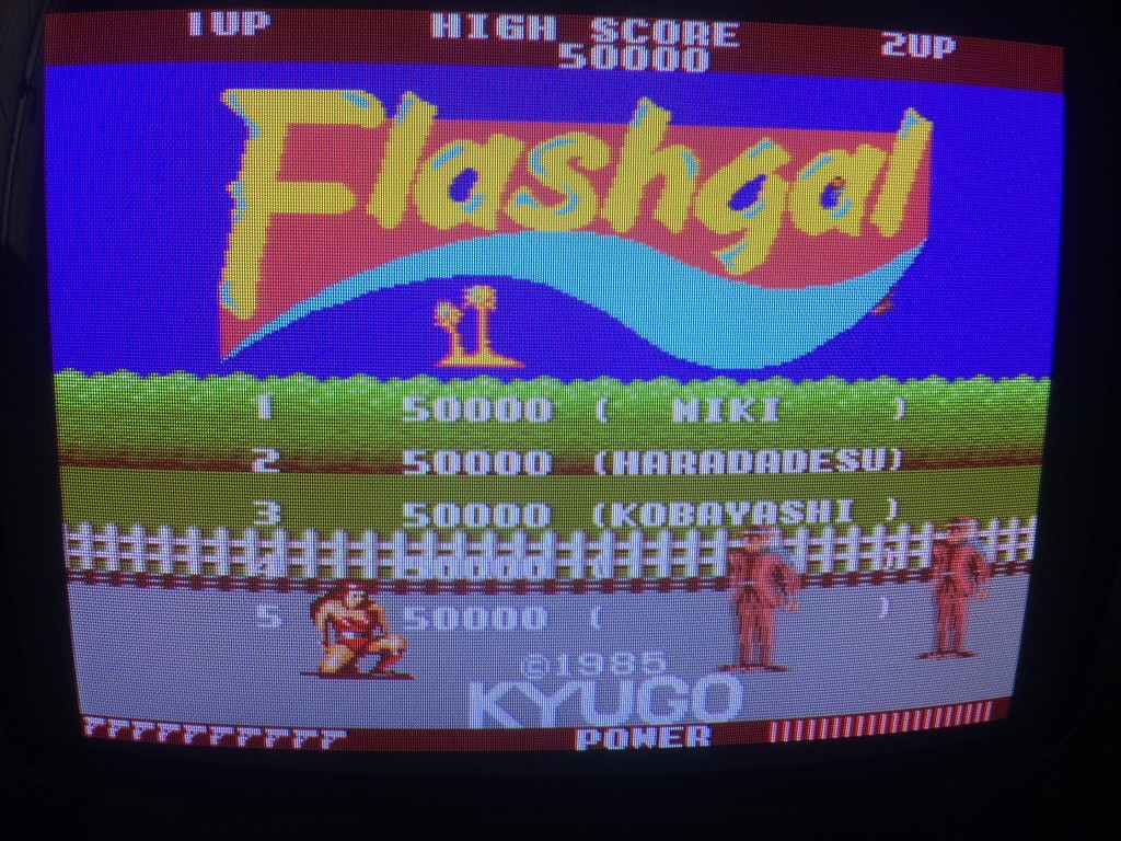
This completely fixed the colours on the pcb with no artifacts:

Again a big thanks to Elgen from https://elgensrepairs.blogspot.it/ for the invaluable tool and to Caius and Porchy for being always very helful
