Caius

Nastar (World) PAL dumps added

 PAL Updates  Comments Off on Nastar (World) PAL dumps added
May 062014
 

I just dumped the two PALs from an original Taito Nastar (World) PCB.Both devices (AMPAL16L8B)  were unlocked so I read them with a standard EPROM programmer, disassembled into their equations using JEDUTIL MAME utility and then recompiled into GAL16V8 format under WinCUPL.Besides, I can confirm that my dumps match the ones present in MAME.Anyway I have no way to test them since the PCB is faulty so we would appreciate if someone with a good board could test them and report feedback, thanks.

 Posted by at 9:54 pm

Bucky O’ Hare repair log #1

 PCB Repair Logs, Repair Logs  Comments Off on Bucky O’ Hare repair log #1
May 062014
 

Got this original Konami Bucky O’ Hare PCB for quite some time but I never looked at:

100_5295

Once powered on it displayed good graphics but loud, scratchy and distorted sound.Everyone in the arcade world knows that this kind of PCB use an hybrid custom sound module, in this case it’s the  one marked ‘054986A’ (other games like X-Men use the ‘054544’ one) which is famous to go bad (in particular its SMD electrolytic capacitors will leak sooner or later damaging tracks).Well, with these premises, I decided to do a full recap of the module following this chart:

https://jammarcade.net/images/2024/05/KONAMI_HSC.pdf

I opted for a different solution.I used tantalum SMT tantalum capacitors instead of electrolytic through hole or SMD ones.Why will you say?Because tantalum capacitors are extremely reliable, they don’t suffer from leakage and have a lower ESR.Last but not the least, they are also more elegant than electrolytic one like you can see in this comparison at the end of my recap/repaint job :

054986A_combined

Anyway once powered on again the board I got same sound issues.I know this custom module has additional circuitry also on the underneath.So, I was force to desolder again the module but this time I socketed it using a 64 pin SDIP (shrink DIP) socket divided in two stripes for an easy future maintenance:

S-DIP_socket_combined

After desoldering it, I found this scenario:

100_5291

In particular there is a QFP Konami ASIC marked ‘054321’ (probably a MCU which controls the entire sound system, infact if you run the PCB without it the RAM/ROM test will show error on all related sound components -RAM, ROM, 74LS245 and ASIC ‘054539’).Besides there are also a JRC4558 OP-AMP (LM358 compatible) and a AD1868R (Dual 18-Bit Audio DAC), all in SMD package.

Judging from the issue  I started to suspect about the 4558 OP-AMP.So, I borrowed one from a faulty PCB. After a quick soldering  I turned on the PCB again and..the sound was back, crystal clear as it should be.Mission accomplished.

 Posted by at 8:03 pm

Raiden II (set 4, Italy revision) PAL dump added

 PAL Updates  Comments Off on Raiden II (set 4, Italy revision) PAL dump added
May 032014
 

After repairing it (see log here) I dumped the two PALs from an original Seibu Raiden II (set 4, Italy revision) PCB.One dump is tested and working on a GAL16V8 replacement.The other one was good apparently but when I  tried it  on the PCB I got sprite issues.The original device is a PEEL18CV8 and it seems that it has been programmed as registered (PIN1 is tied to a 16MHz clock signal) so we can’t do much about for now.So, this is a partial set.

 Posted by at 6:38 pm

Raiden II repair log

 PCB Repair Logs, Repair Logs  Comments Off on Raiden II repair log
May 032014
 

Got a cheap Raiden II (set 4, Italy revision) PCB recently:

Seller claimed PCB had a video SYNC issue so I fired up it sure of the scenario I was going to face :

There was no SYNC at all (measured 549Hz on pin13 solderside of JAMMA edge) but the thing that made ​​me suspicious was that there was no activity on address/data bus of CPU (NEC V30) and program ROMs like the system never got initialized.

So, as usual, I start my visual inspection and found this:

If the missing capacitor  (which filters the +12V for the LA4460 audio amplifier) was not the cause of the issue for sure, I thought the broken track would have been the culprit but  I was wrong since, once restored, I got the same rolling screen above.

PCB has few common ICs (74LS245 and SRAM mainly) but a sufficient number of ASICs so I consulted the MAME source which is like a bible for every arcade repairer since it’s a an inexhaustible source of hardware information.And I found that among the various ASICs, the one marked ‘SEI1000 SB01-001’ is responsible of the main protection, this would have explained why the PCB didn’t boot at all:

Its package was a 184 pin QFP with a fine pitch as you can see from picture.Armed with a small needle I started to test the tightness of each pin and found that almost half of them got detached from the pads when I gave force.So, it was time for a reflow at 390° with my hot air station which I had to repeat 4-5 times plus some final passes with the tip of the soldering iron to get a good result.

Powered up again and :

SUCCESS!Another PCB saved from the trash and a very good vertical shoot ’em up!

 Posted by at 4:15 pm

Bionic Commando repair log #2

 PCB Repair Logs, Repair Logs  Comments Off on Bionic Commando repair log #2
May 012014
 

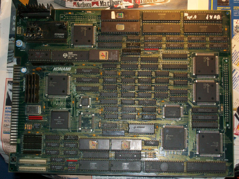
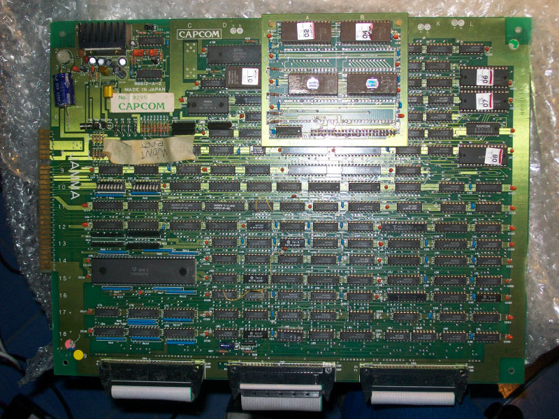
Another new day, another PCB repair. An easy and lucky one with a strange epilogue though.Got this original Bionic Commando PCB from Ebay as non working:

IMAG0236

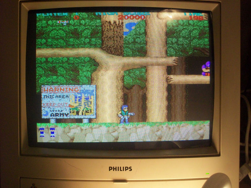
When I received the board I noticed a piece of tape on it saying “WON’T BOOT” so I was ready to a static garbage screen or worse, a nice black one.So I powered up the board and I got this instead:

IMAG0239

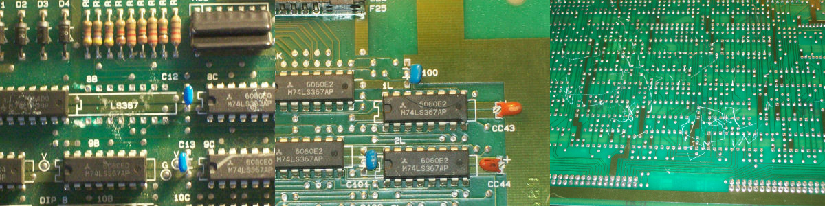
Video had jailbairs all over the screen, gameplay and sounds were OK.So, as usual, before starting my troubleshooting, I made a visual inspection that revealed :

One 74LS367 was missing, another one was cracked and, the icing on the cake, solderside of the video board had a lot of scratches but at the end I found only one broken track that I jumpered with a bit of solder.

So, fitted a new 74LS367 and replaced the cracked one, I was confident about but I was wrong, there was no change at all, jailbars were always present.

So, with the help of the schematics, I started to check everything related to the issue .I dumped the ROMs containing the tiles and they were fine against MAME,  did some in-circuit testing with my B&K 560A IC tester but nothing was wrong in the presumed involved parts of circuit.After some hours of investigations I was giving up when I decided to check the voltages on PCB.I measured +5.1V on a IC so I lowered it a bit but without immediate success.A little frustrated I powered off the board and then after some minutes on again and I got:

IMAG0238


I don’t know if this is really related to the voltages (I raised to +5.1 again and jailbars didn’t appear), the fact is I finished the game and no issue occurred again.Oh, I love the soundtrack of 1st level, it reminds me the happy days playing this game on my Commodore 64.Another day spent, another great classic added to my collection…

 Posted by at 9:25 pm