He said me board had some GFX issues.Actually when I powered it up I got no sprites at all:
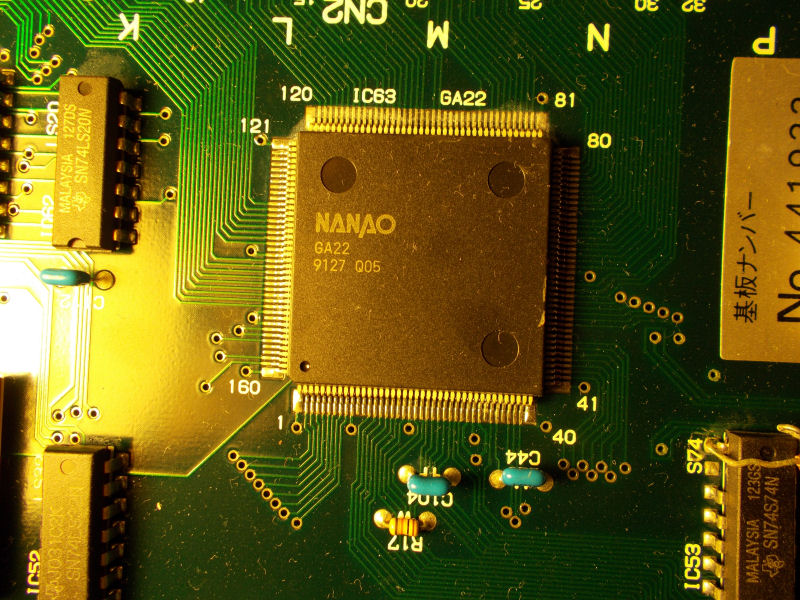
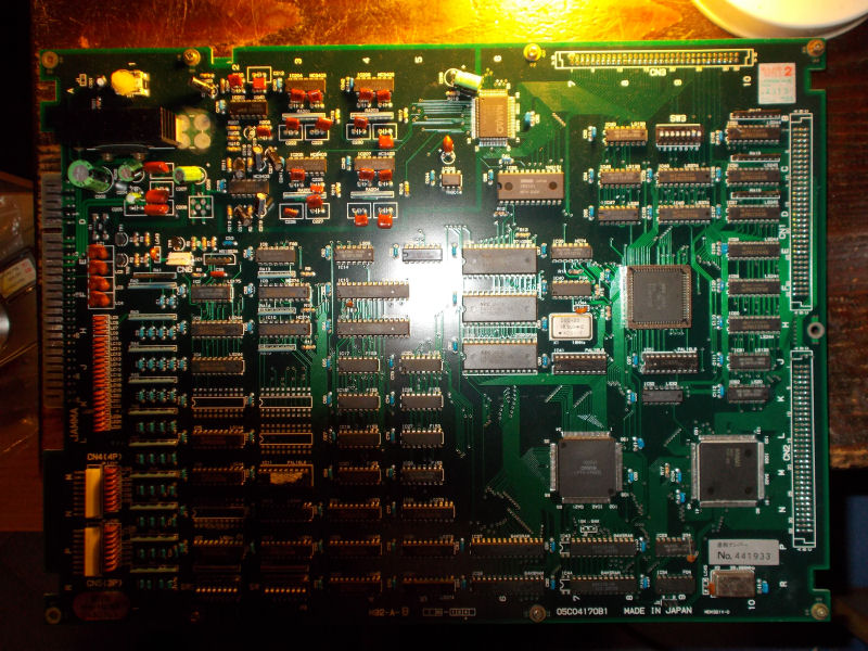
For first I checked the sprites EPROMs with my logic probe and found no activity on all pins.These four sprites MASK ROMs on video board are addressed by the ASIC “GA22” on CPU board :
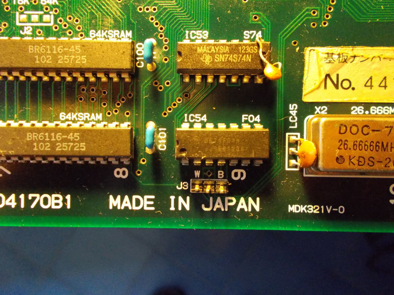
I probed it and all its pins were silent too.I tried to reflow it without luck, sprites were still absent.Then, looking at the board, I noticed an open jumper ‘J3’ right hear the GA22 ASIC:
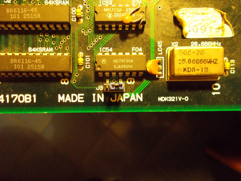
Looking at other M92 CPU boards I could see that this jumper was always closed to position ‘B’ (so with central and right pins shorted together).So I did it on my board too:
and sprites were magically restored!
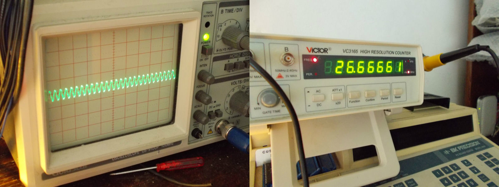
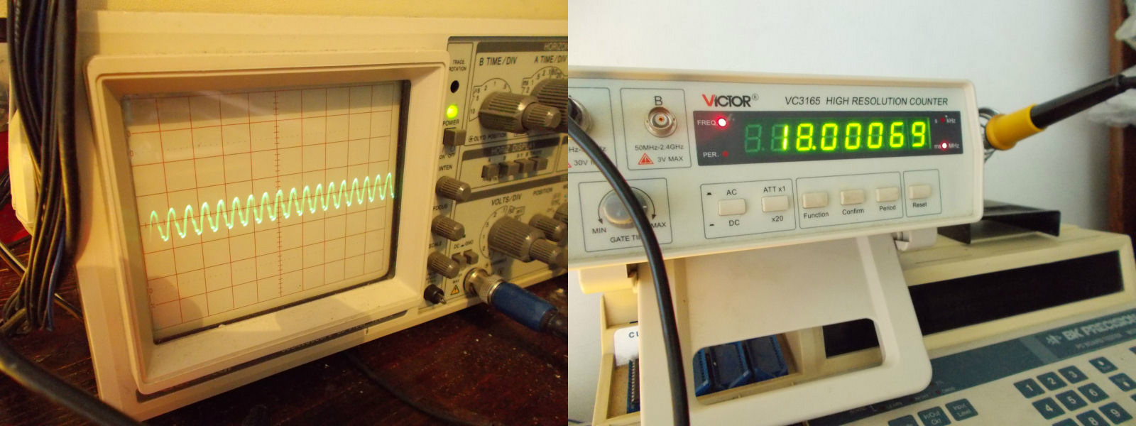
Now the technical explanation.The jumper is actually for selecting which clock signal must be delivered to the sprites generator ASIC “GA22”.If closed in ‘B’ position, ASIC will receive a clock signal of 26.6666 Mhz (which is the correct value for most of M92 games) :
If closed in ‘W’ postition, the ASIC will get a 18.000MHz signal (no sprites with this configuration) :
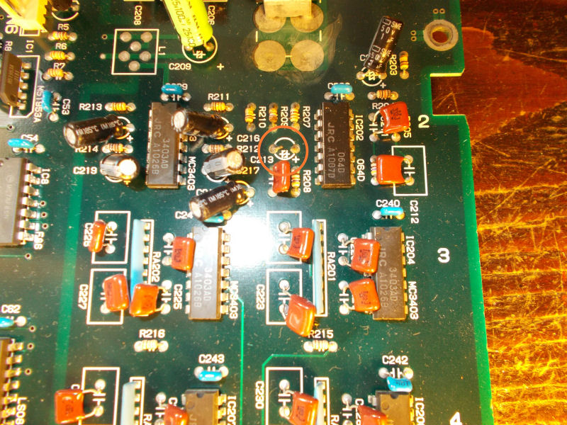
Last issue to fix was some audio background noise:
I quickly traced it to a missing 47uF 16V electrolytic capacitor @C213 in analog sound section:
PAL UpdatesComments Off on Slam Masters (US) CPS 1.5 PAL dump added
Sep182015
In the past days ‘coolmod’ dumped the PAL from his Capcom Slam Masters (US version) CPS 1.5 PCB.PLD was an unlocked PAL16L8 so he provided both original and GAL16V8 .jed and successfully tested the latter.Thanks to him.
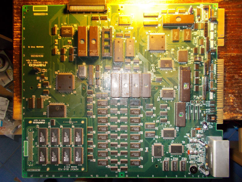
Got this NebulasRay PCB ( converted from another Namco NB-1 game) from my friend Josef for a repair:
For the uninitiated the game is a vertical shoot ’em up released by Namco in the 1994.It runs on Namco NB-1 platform.Here are the specs:
Main CPU: Motorola 68EC020 32-bit processor @ 12.5 MHz (for the NB-1 games), 24.192 MHz (for the NB-2 games)
Secondary CPUs: Namco C329 with C137
Custom graphics chips: Namco C123, C145, C156 and C116 (for the graphic effects) with Namco C355, C187 and C347 (for the motion objects)
Sound CPU: Namco C351 (utilized for the NB-1 games), Namco C75 (Motorola M37702-based 16-bit) @ 16.128 MHz (utilized for the NB-2 games)
PCM sound chip: C352 @ 16.384 MHz that supports 8-bit linear and 8-bit muLaw PCM with four-channel output
Control chip: Namco C160
Board composition: two boards (NB-1) or single board (NB-2); an additional “gun” interface board was also utilized for Point Blank.
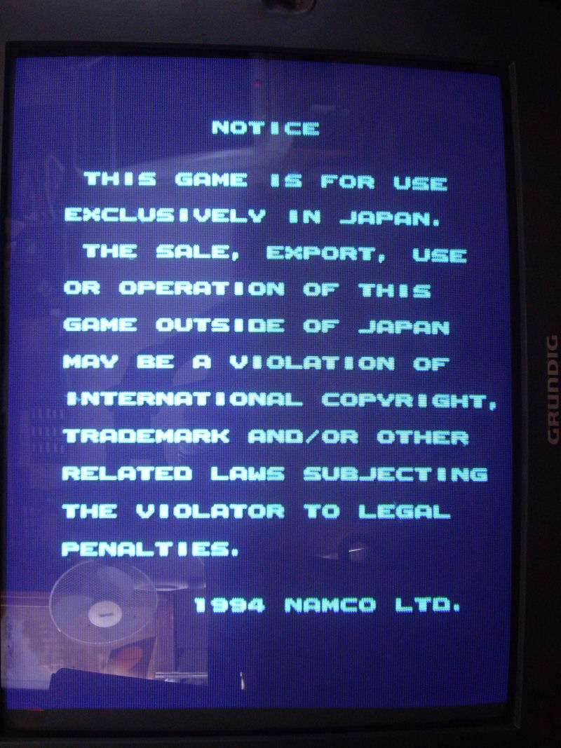
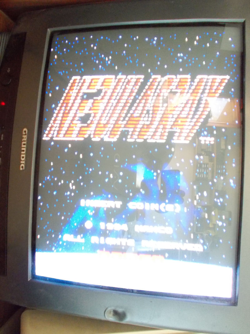
Board actually booted but didn’t pass the disclaimer screen:
As said, main CPU is a 68EC020.Probing it, revelead a good activity until it got stuck on the above screen, at this point most of control lines were going to high impedance state terminating the BUS activity.So, there had to be some trouble in the main code execution but, given the hardware complexity and lack of documentation, I was pretty lost.
I started to do some tracing on PCB so I could locate the WORK RAMs ( two Toshiba TC551001 @5C and 6C):
I figured out that they were not addressed directly by main CPU but through the near custom C351 (which is actually the custom sound CPU).I replaced both RAM but without luck.So, I removed the custom C351 and checking traces underneath it I found two breaks which I patched with some tiny wires:
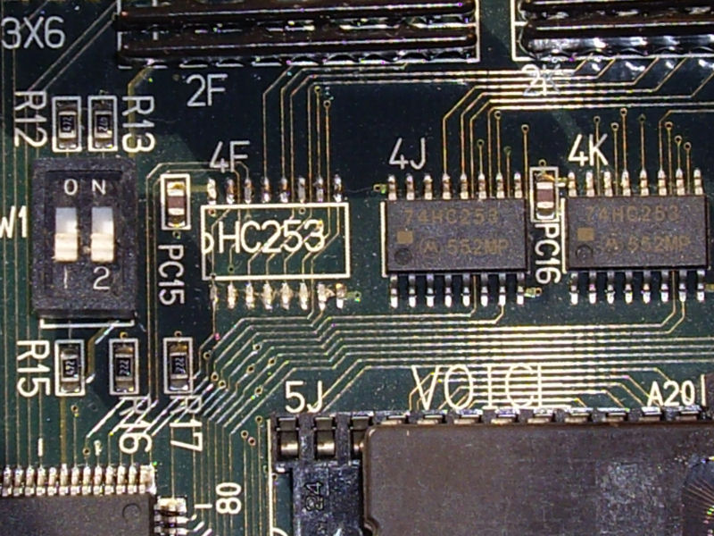
With this fix the board passed the initial disclaimer screen but went straight into test mode although dipswitches were set to off.I quickly traced this to a missing 74HC253 multiplexer @4F:
Finally the board entered in game but all sprites were wrong :
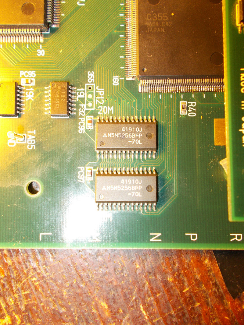
Object RAMs are two Mitsubishi M5M5256 @20M and 21M:
A closer inspection revealed some loose pins that I promptly resoldered.In this way all sprites were restored except for jailbairs on some of them (like game title ):
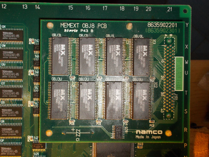
All sprites ROMs are on the small daughterboard in form of 8 MX29F1610 FLASH devices :
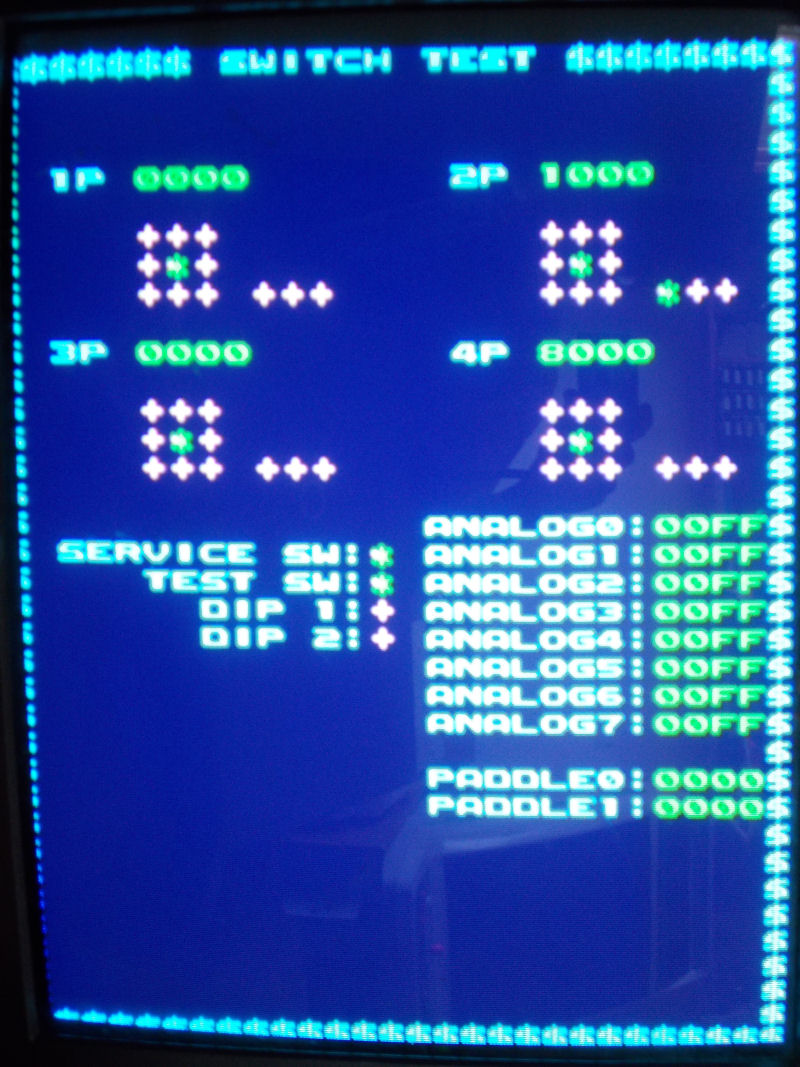
Since the board was a converted one, they were hand soldered not in professional way (let’s say so..) so I reflowed them.Graphics and sound were perfect now but some inputs were missing or stuck like reported in switch test:
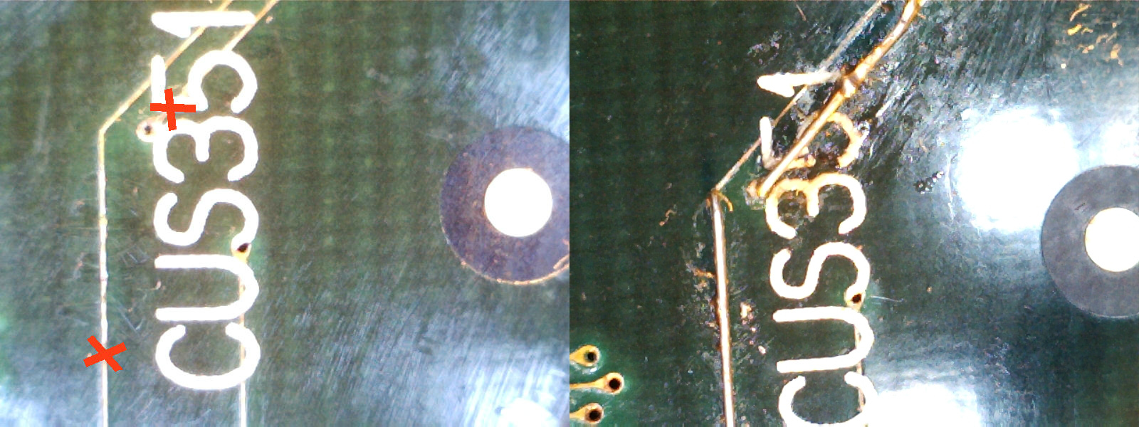
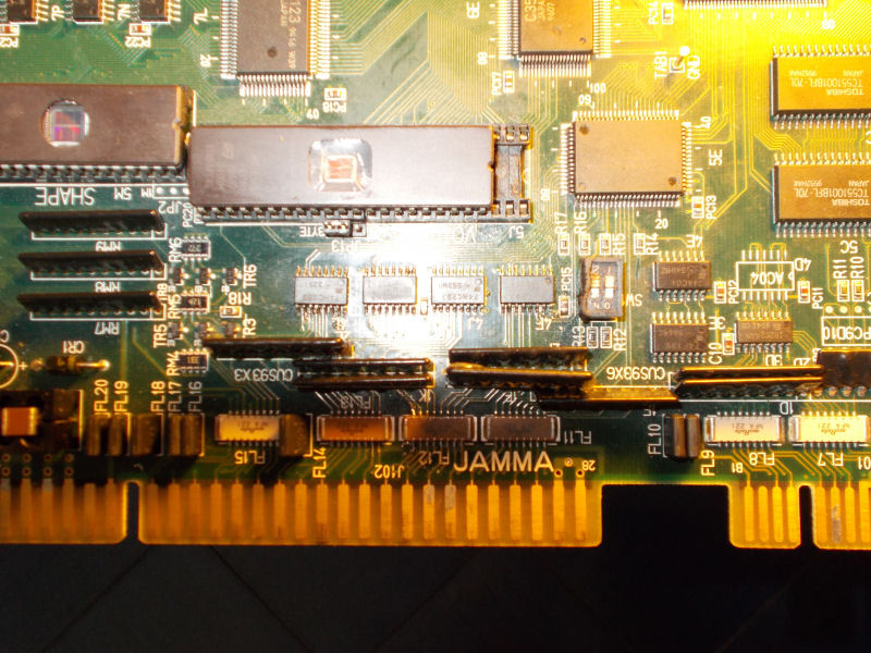
The inputs circuitry is so designed on this kind of hardware : JAMMA connector pin is connected to some EMI filter arrays , then to some custom CUS93 resistor arrays, then to some 74HC253 which combine inputs into outputs that go to the ASIC C160 (which is the I/O chip):
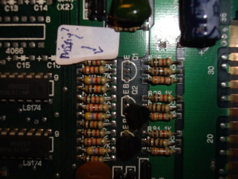
After some tracing I could pinpoint the faults in two bad CUS93 resistor arrays @2L and 1F:
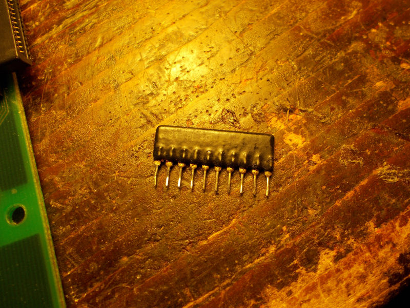
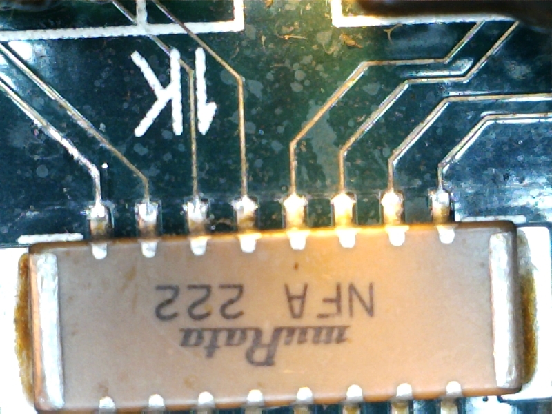
Besides, there was intermittent contact between some pins of JAMMA connector and EMI network filter array @1K:
‘coolmod’ dumps the original PAL ‘VA63B’ @1 on his Varth (US revision B) CPS1 PCB.This dump replaces the handcrafted one made by Shoestring some time ago.
Andreas sent dumps from a Blood Brothers original PCB from TAD Corp.
They are made from 5 unprotected PLDs (GAL16V8 and PAL16L8) except protected U0242, U034 and U076.Dumps are untested because of a missing custom chip.
Thanks to both.
I dumped the three PLDs from a Macross Plus PCB.Original devices were three GAL16V8B, they were unsecured so I could read them with my EPROM programmer.
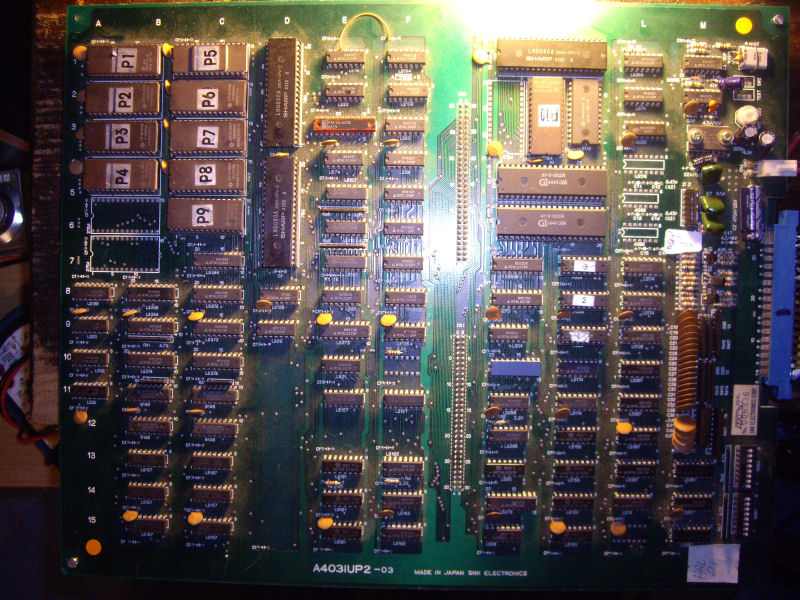
Got this HAL21 PCB from my frend Josef for a repair.The game is a vertical shoot ’em up produced by SNK in 1985, a mix between Xevious, Terra Cresta and Alcon.
Board was in good shape given its age:
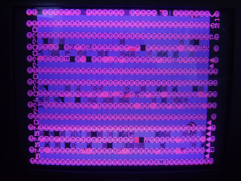
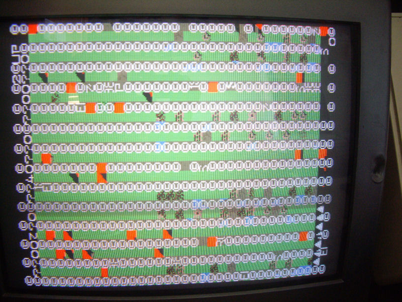
but fautly since it didn’t boot at all, stuck on a static garbage screen:
First thing I noticed (besides the fact that it didn’t boot) was the wrong colors, specifically the red one was missing. My friend Josef gave me an hint pointing me to a missing transistor 2SC1815 @Q1 near the edge connector:
Actually this transistor was for driving the RED ouput (the other two are for BLUE and GREEN) so replacing it restored correct colors:
So, I started my real troubleshooting .Hardware is made of two Z80 CPUs ( a main and sub one) plus a third one for the sound.I decided to hook up my Fluke 9010A in order to perform some test on main CPU.MAME source reports this memory map for the RAMs:
AM_RANGE(0xe000, 0xe7ff) AM_RAM AM_SHARE(“spriteram”) // + work ram
AM_RANGE(0xe800, 0xf7ff) AM_RAM_WRITE(marvins_bg_videoram_w) AM_SHARE(“bg_videoram”)
AM_RANGE(0xf800, 0xffff) AM_RAM_WRITE(snk_tx_videoram_w) AM_SHARE(“tx_videoram”) // + work RAM
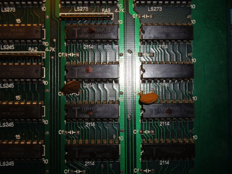
When I performed a long RAM test on the first and third address spaces, I get an R/W error from Fluke 9010A.With the help of its probe, I could located the involved chips, eight 2114 of video board:
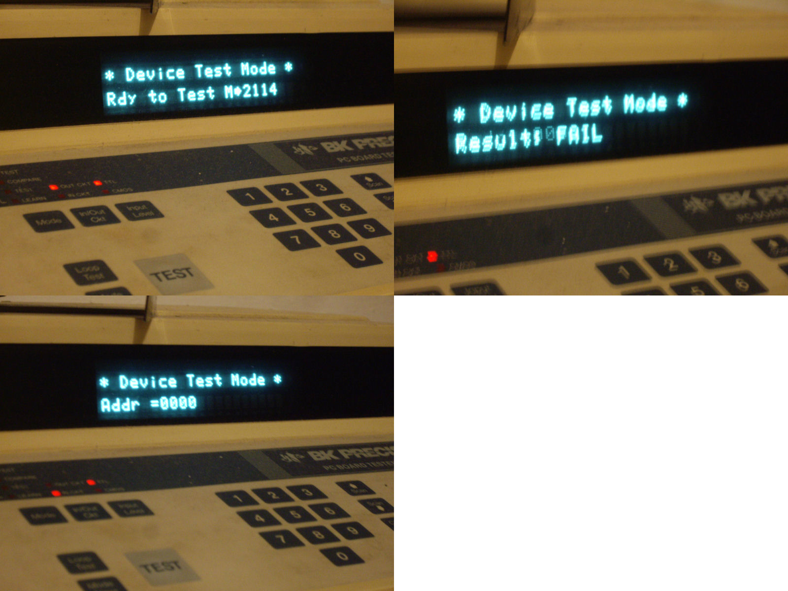
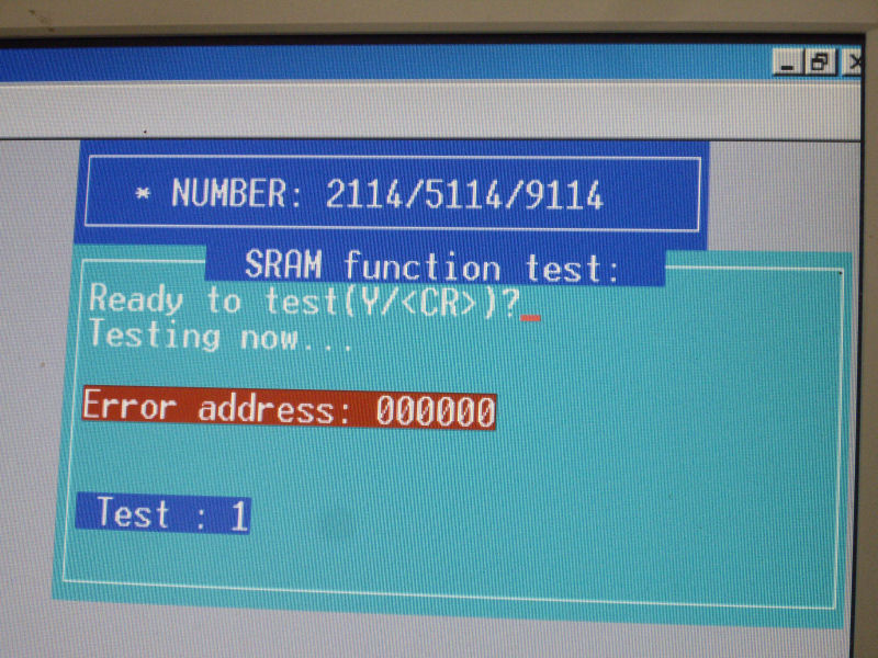
I probed them with my BK Precision 560A in-circuit tester which reported bad devices for the four ones on the right :
I took this result with reservations, most likely not all four chips were bad but one certainly and this affected the other ones (due the fact they share same address bus) misleading the tester.Not being able to accurately identify the faulty chips I desoldered all the four and I found two bad ones @6L and 7L:
With two good 2114 RAMs fitted, the board properly booted with no further issues.Mission accomplished.

 X i
X i