PAL UpdatesComments Off on Another Out Run PAL dump added
Apr202016
Today I dumped another PLD from an Out Run PCB.Original device labeled ‘315-5228’ (@IC123 on VIDEO board) was a CK2605, I read it as PLS153 and then reduced the fusemap using the PLAD utility by Charles MacDonald.Lastly I recompiled the disassembled equations in a GAL16V8.
GuidesComments Off on Using a lightgun with Operation Wolf PCB
Apr052016
Some days ago I received an Operation Wolf PCB bought from Hungary.After dumped ROMs and comparing the board layout with pictures on the web it turned out to be a rare prototype which runs unprotected code (it lacks of the C-CHIP IC).I suggest you to read the whole story on David ‘Haze Haywood ‘ homepage:
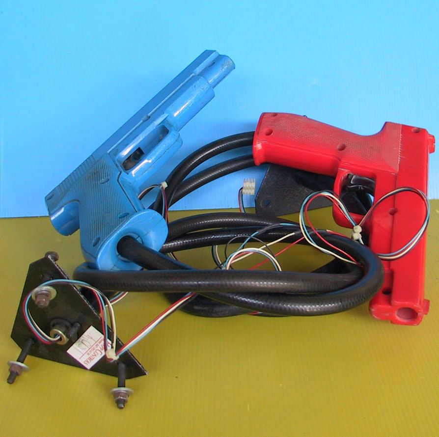
After adapting the board to JAMMA, I fired it up and it was perfectly working.Reading on the Web, there are conflicting opinions if this board is a simpe lightgun game or it uses analog joystick like some many people claim.So I wanted to try myself and bought a couple of cheap Happ lightguns widely used on games like Lethal Enforcers :
All lightguns work in the same way: you’re pointing your gun at the screen, and the gun is essentially a light sensor.When the part of the screen which the gun is pointing at gets flooded in white, the sensor detects it and sends a signal to the game: “I can see white now, I’m pointing at the part of the screen you’ve just drawn”. At this point the game can work out how far down the screen it has drawn, and how far along the current line, which gives a pretty accurate position of where the gun is pointing.
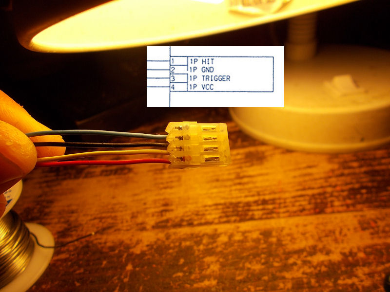
The Happ gun has a 4 PIN connector and looking at Lethal Enforcers schematics, this is the pinout:
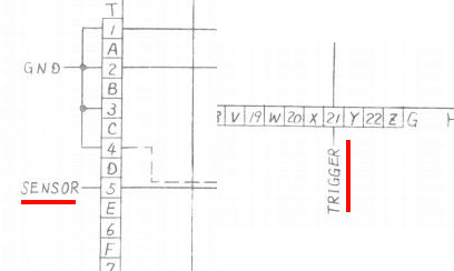
The ‘HIT’ signal (so called in Lethal Enforcers but name is relative) is an input on arcade PCBs and it’s essentially the output of the optical sensor (a phototransistor) mounted inside the gun.The ‘TRIGGER’ is the switch inside the gun and it’s shorted to GND everytime, indeed, you pull the trigger.VCC and GND are obviously needed to power the electronics inside the gun.With this info it was very simple to adapt this gun to the Operation Wolf PCB.The pinout of this board shows ‘TRIGGER’ signal on pin 21 parst side of ‘G’ edge connector on main board and ‘HIT’ (called ‘SENSOR’ in service manual) on pin 5 solder side of the ‘T’ edge connector on sound board:
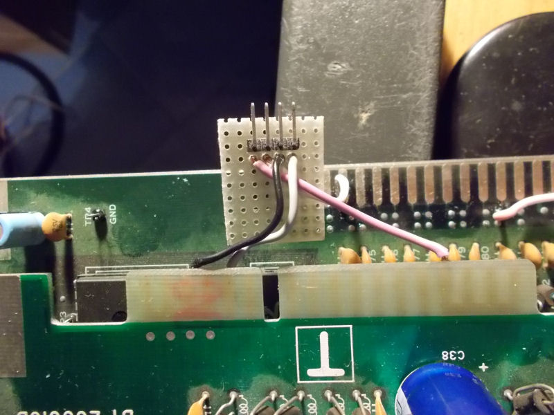
For a better interfacing of the gun to the PCB I used a 4 pin right-angle male header mounted on a piece of veroboard:
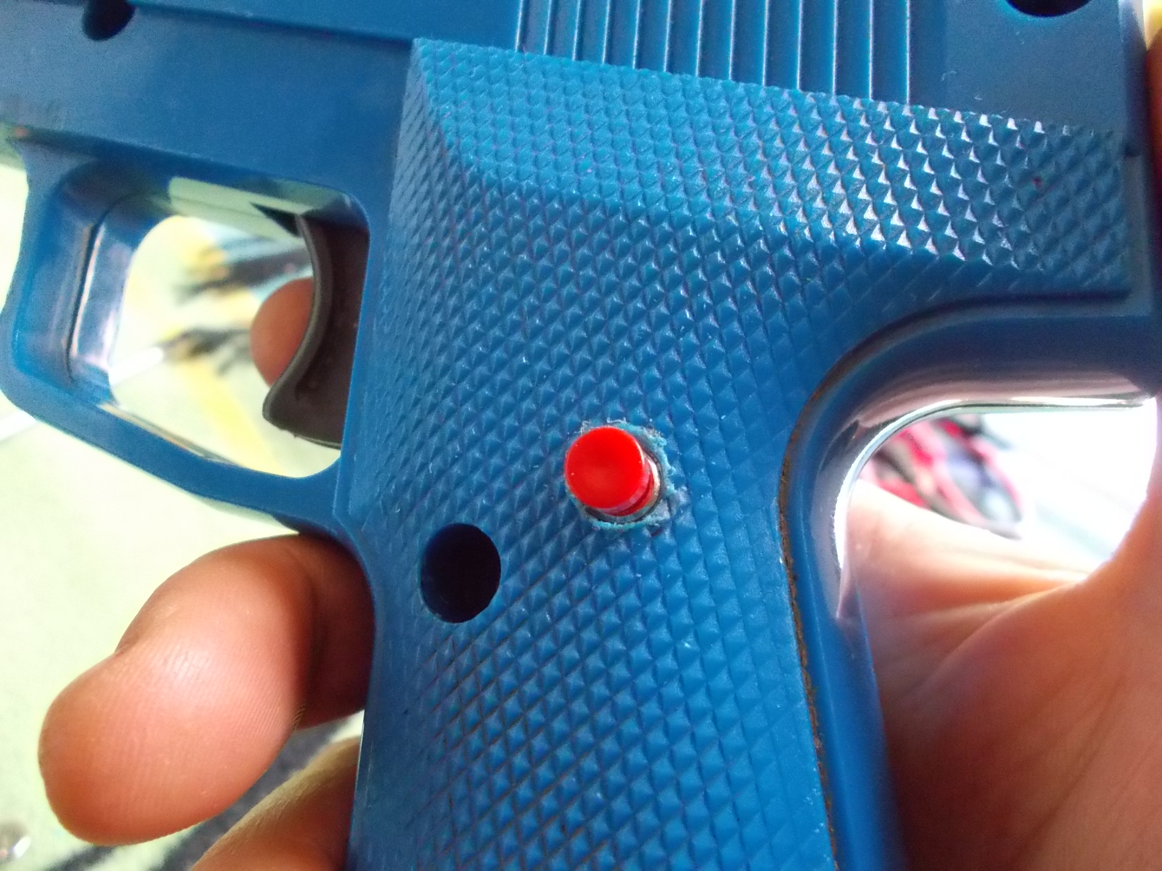
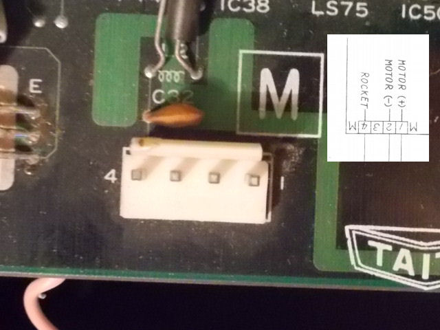
Lastly, since Operation Wolf use another input for rocket and this Happ gun lack of a second switch, I added a further button (a normally-open one) mounted inside the gun and connected to internal common GND and ‘ROCKET’ signal which is PIN 4 of the ‘M’ connector on Operation Wolf main board (but if you want, you can also adapt a PSX/Saturn Guncon which comes with more than a button)
Finally now for sure I can say that Operation Wolf is a simple lightgun game.So let’s go to play it!
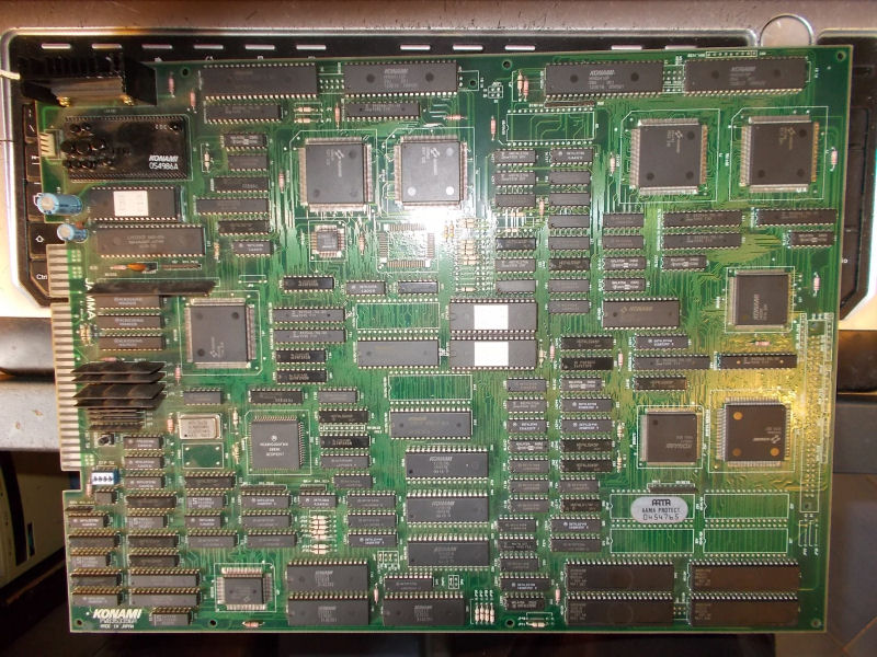
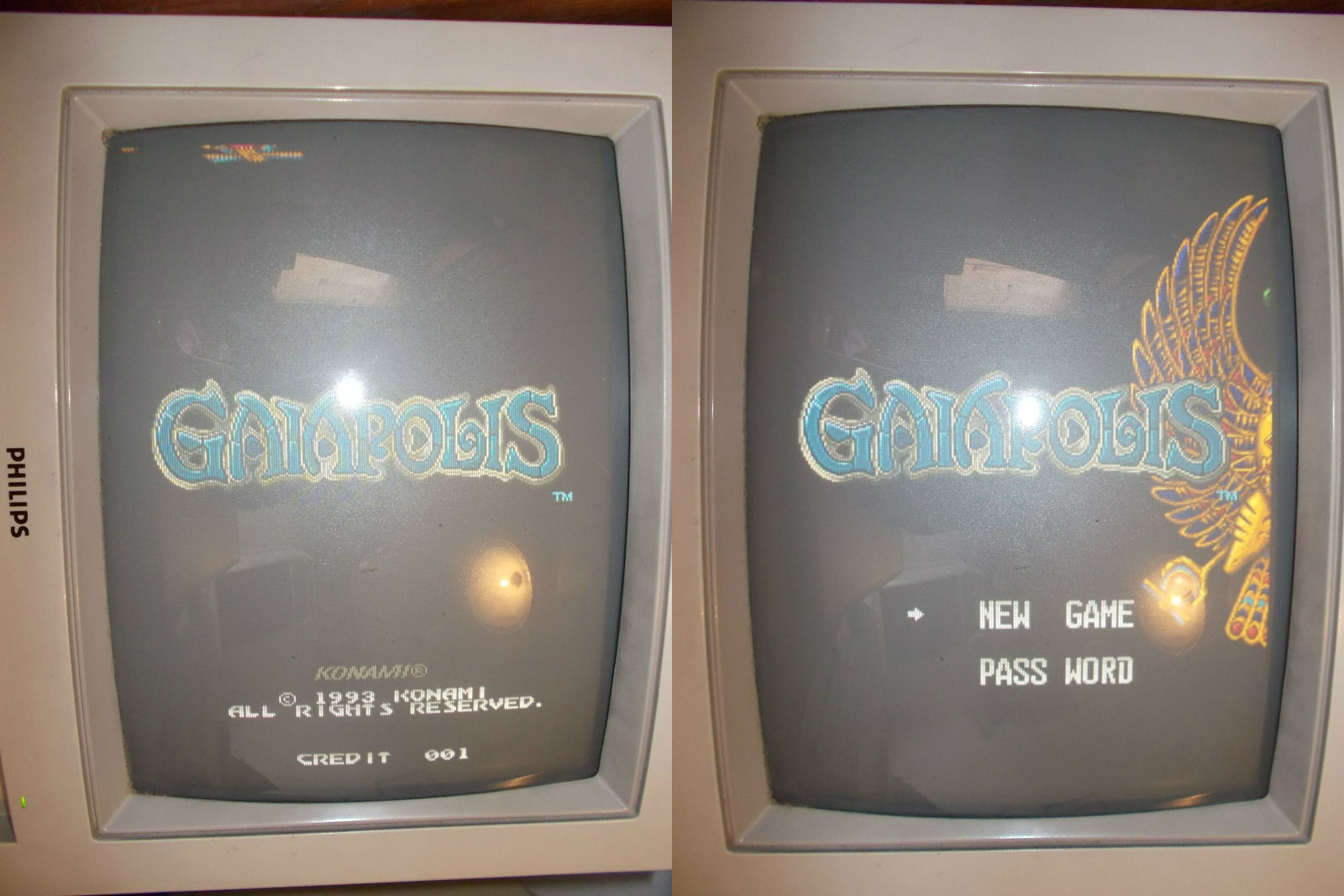
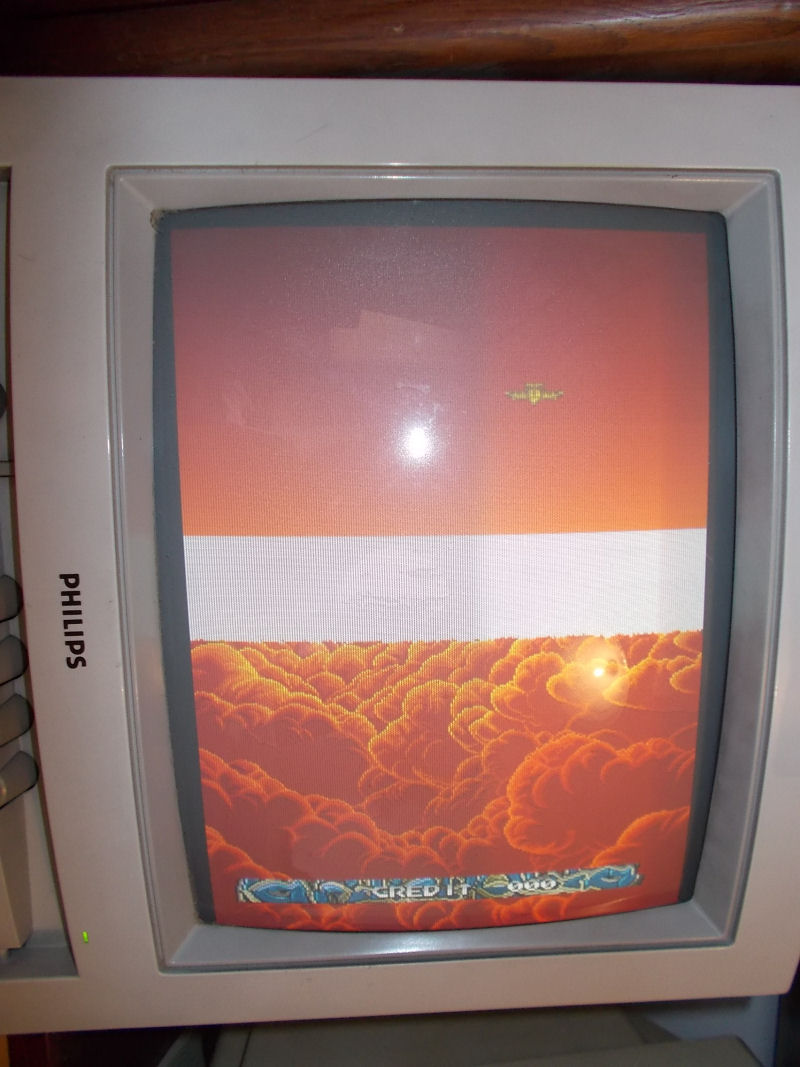
Some days ago I received this Konami Gaiapolis PCB for a repair:
It showed a graphical issue where some background layers were missing but pressing down the PCB they came again although in wrong place:
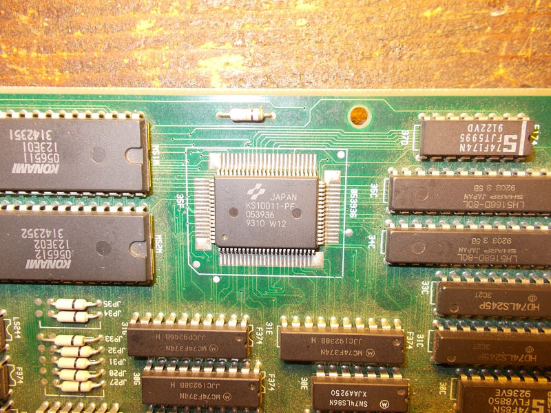
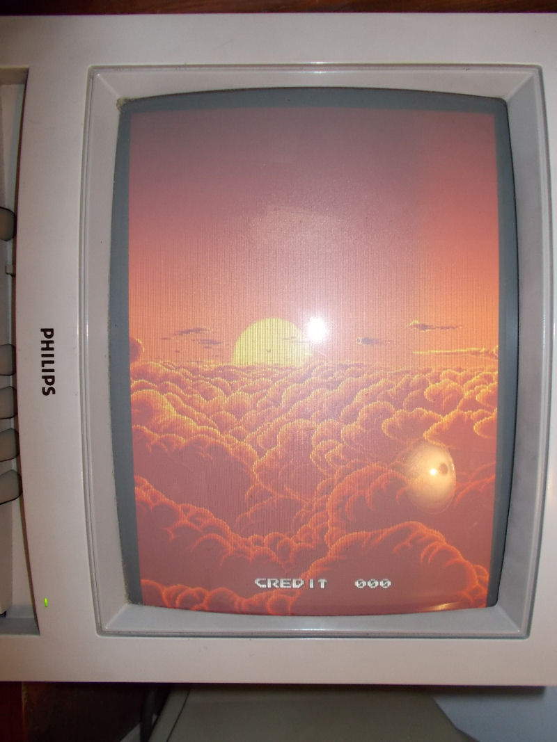
Hardware uses some custom ASICs to generate the various parts of graphics so I made a reflow of the two involved in tiles but this didn’t fix the issue.Using some dummy ROM files in MAME for the backgrounds data I noticed the missing/misplaced graphics were not affected so they were not really backgrounds.The board is capable also to rotate and zoom objects (‘ROZ’) and the ASIC which performs this function is the ‘053936’ :
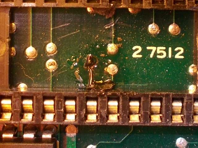
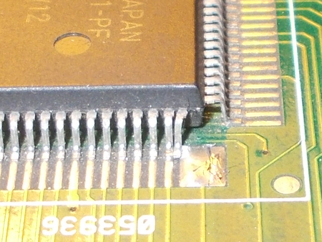
So I went to inspect it and found this:
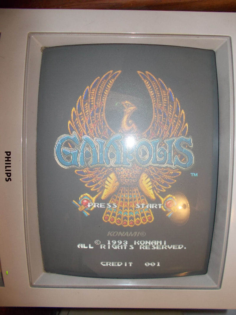
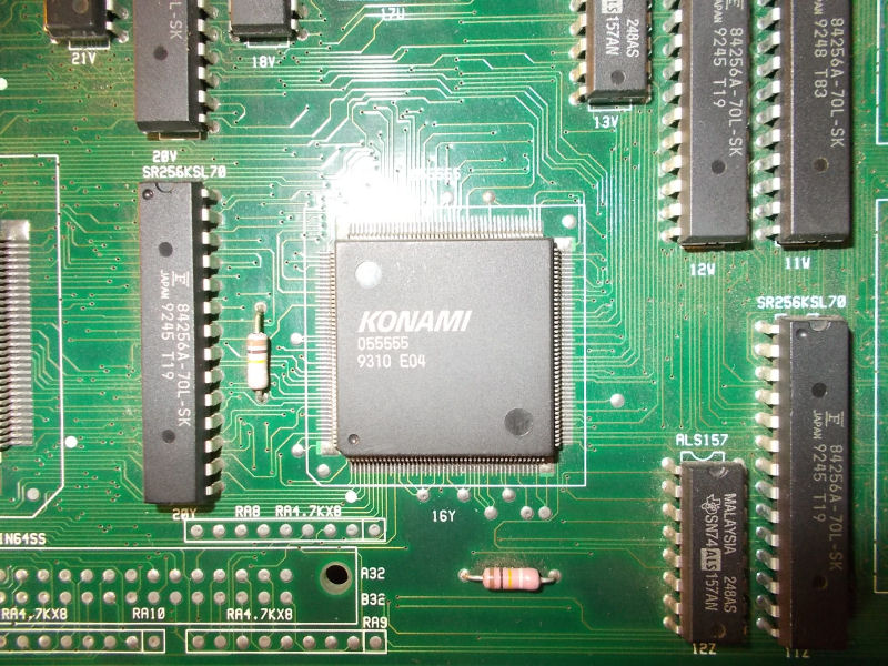
Two pins (connected to data lines of two 6264 RAMs) were touching each other and the rightmost one lost contact with its pad.I restored the proper connections and graphics came back in right place:
I was declaring the board 100% fixed but I noticed some palette/priority issue :
The ASIC involved in this function (it can do other GFX tricks like alpha-blending) is the ‘055555’:
A simple reflow of it was enough to fix the board completely.
PAL UpdatesComments Off on World Rally PAL dumps added
Mar272016
Today I’ve dumped the PALs from a World Rally PCB.Board has five PLDs but I could successfully dump two of them since the other three are registered.Original devices were two TIBPAL20L8 which I reversed and tested fine onto GAL22V10.
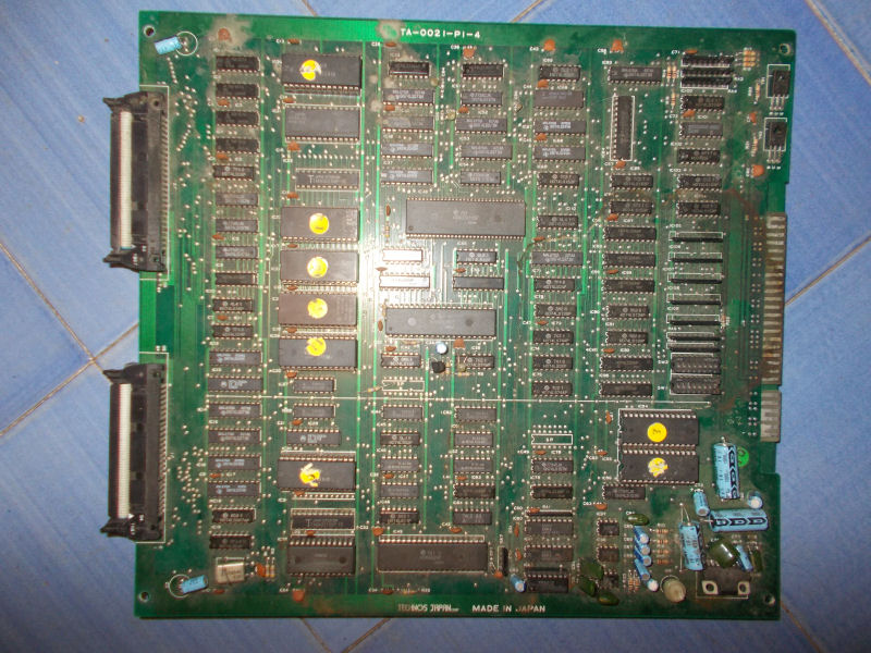
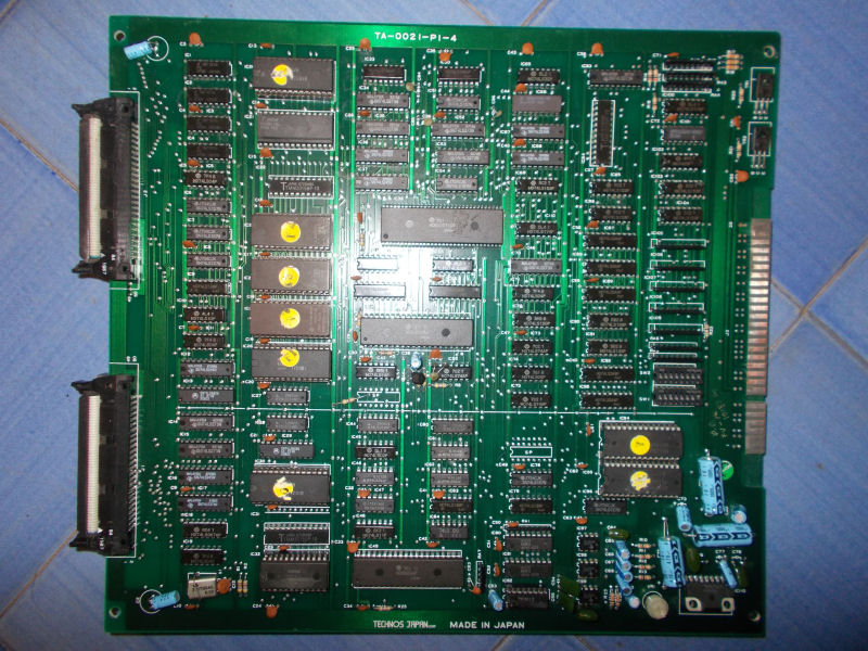
Bought on Ebay this cheap untested Double Dragon original PCB:
Board came in not very good shape, CPU board was really dirty as you can see from picture above.I powered it up and got a solid black screen so I decided to washed it.After dried and removed the oxide from JAMMA connector :
ì
I powered the board again and this time it successfully booted but after started a game I noticed some sound FXs were wrong, replaced only by some noise :
Sound FXs are generated by two MSM5205 ADPCM chips which read data samples from two 27C512:
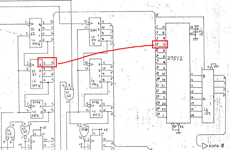
The two MSM5205 were tested good on all pins and piggybacking them didn’t change nothing but when I went to test the two 27C512 I found that pin 7 (address line 4) of the one @IC95 was silent so it wasn’t being addressed.Schematics showed it connected to pin 3 of a 74LS393@IC61 :
:
Jumpering the two pins fixed the issue and all sound FXs were restored but it was an ugly solution so I followed the trace until the point of its break.This lead me under the socket of the 27C512 @IC95 where a pad was corroded and lost contact to pin 7 of this EPROM.I restored the connection with a piece of AWG30 wire after breaking the plastic of the socket in order to reveal the pad:

 ì
ì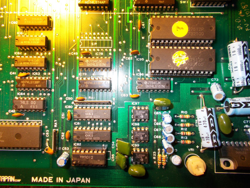
 :
: